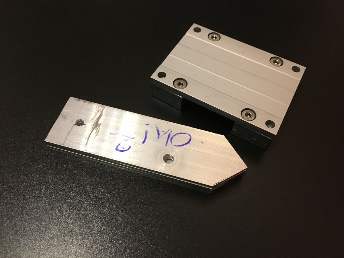
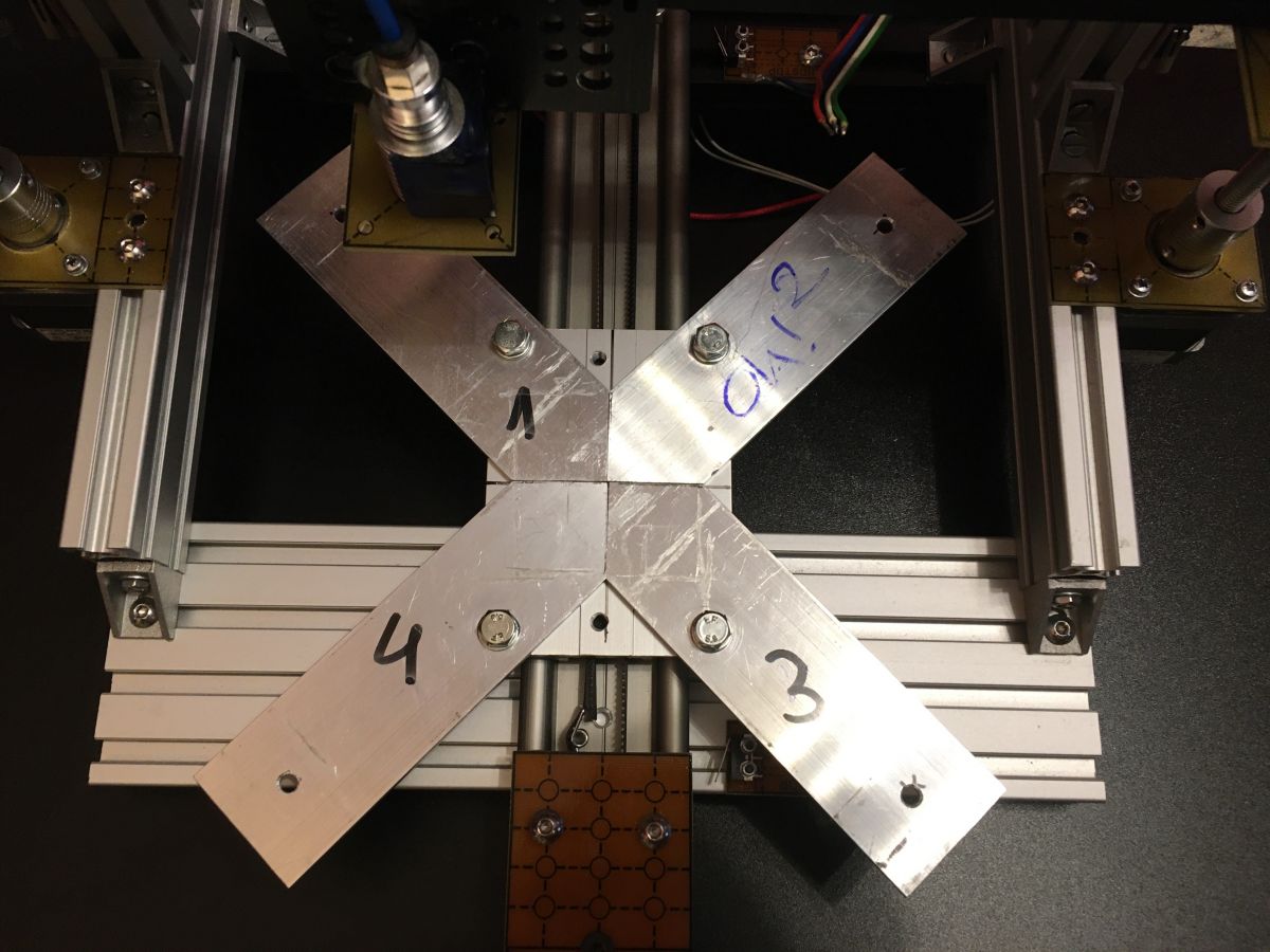
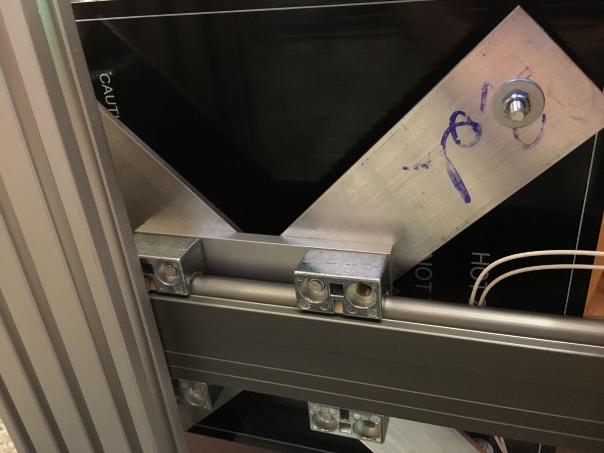
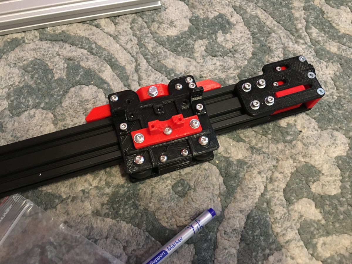
A DIY filament 3D printer was built from T2040 and v-slot profiles, an IGUS linear guide for the Y-axis, and stepper motors from storage.
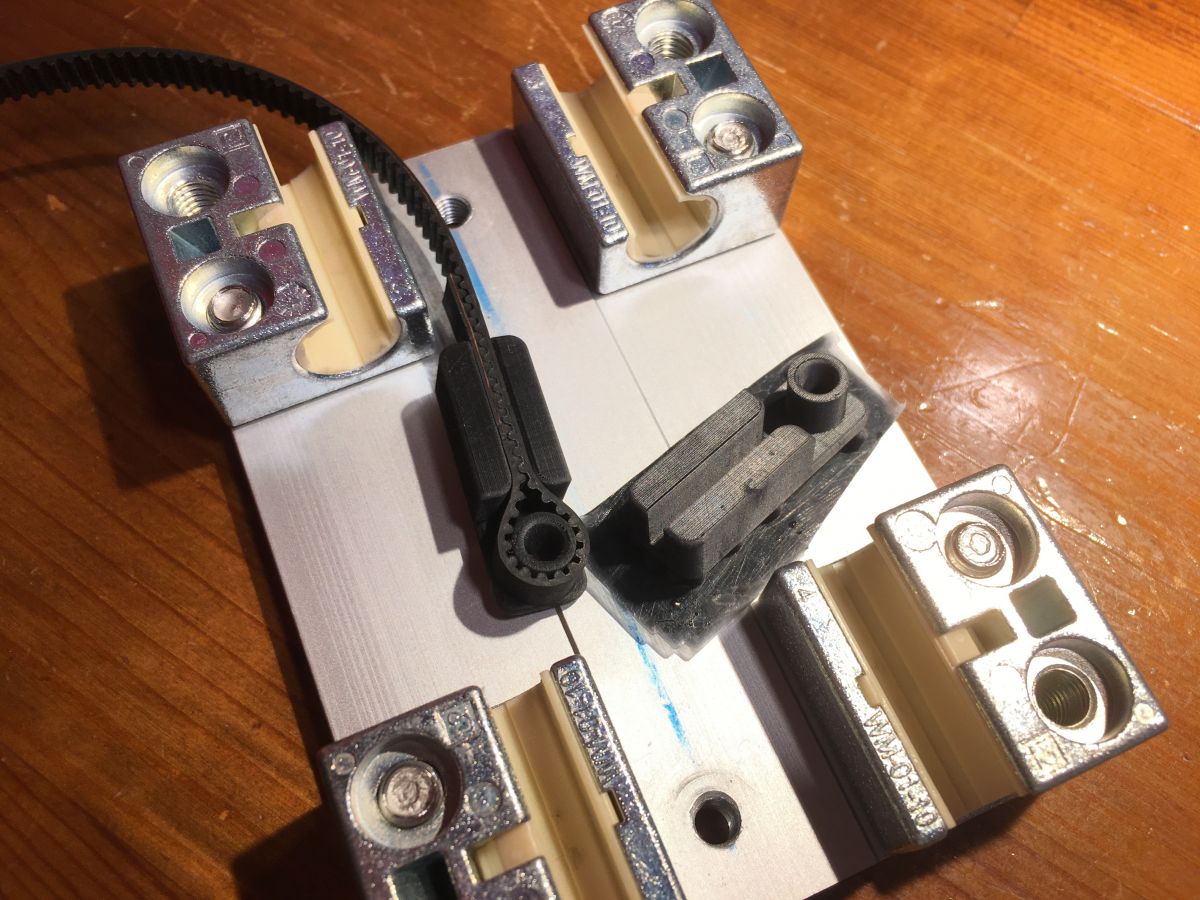
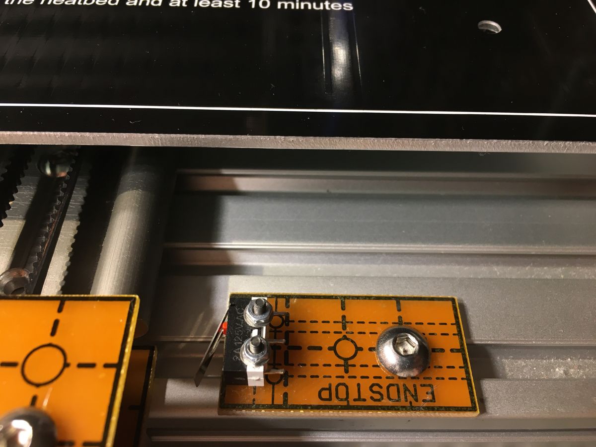
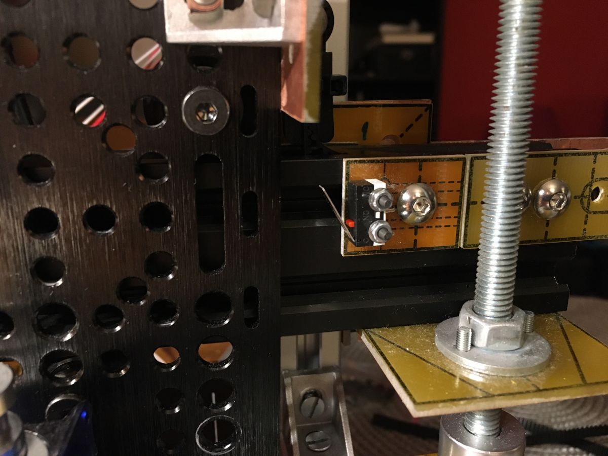
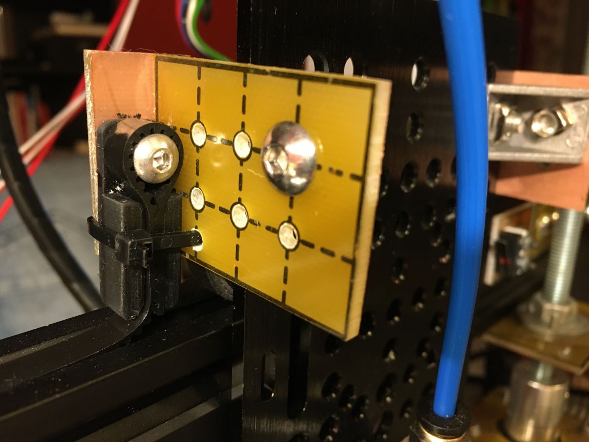
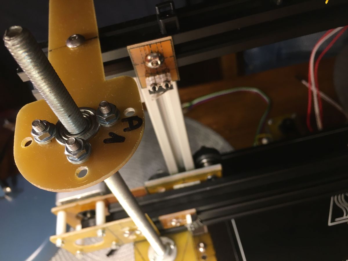
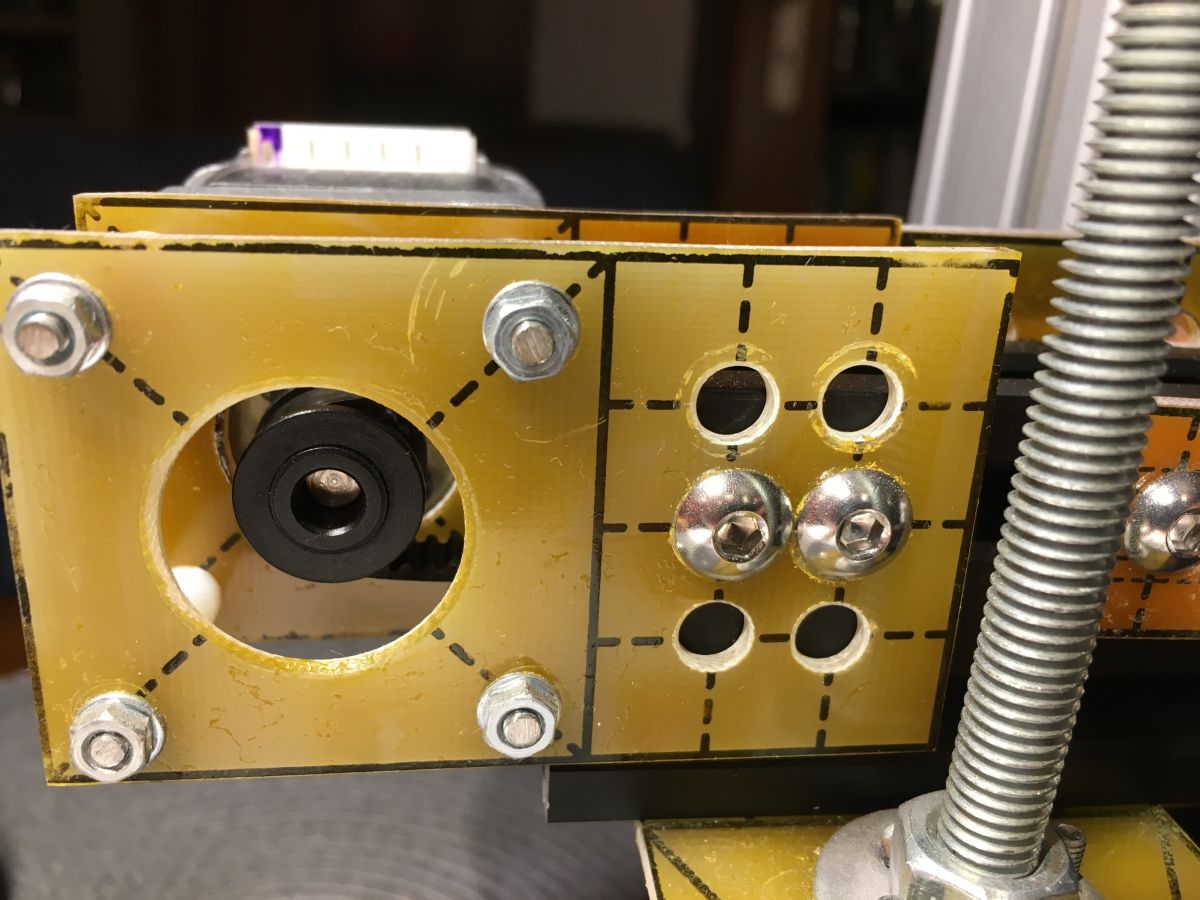
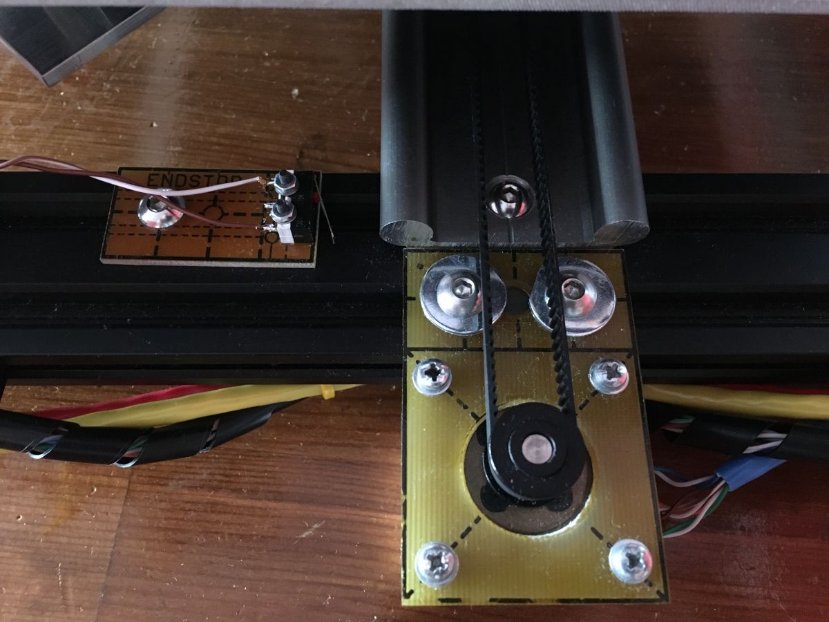
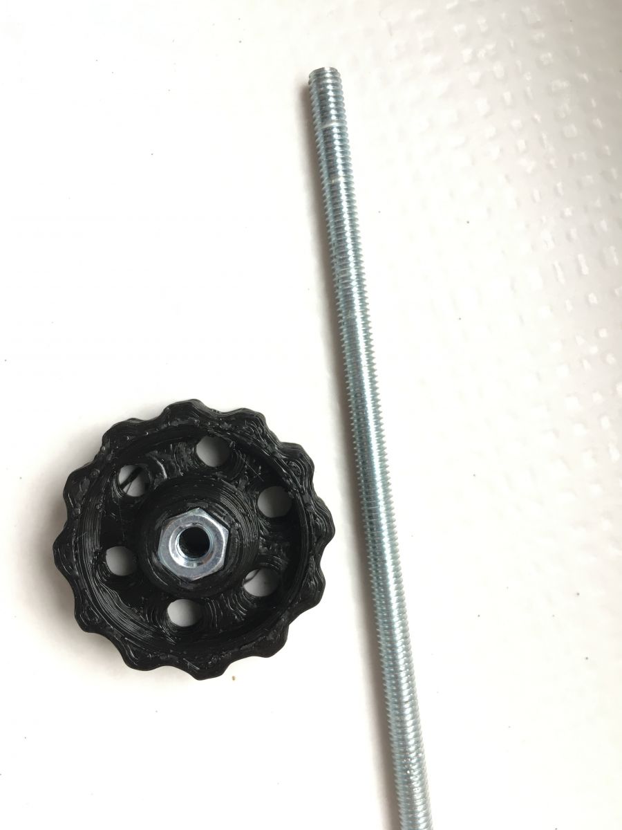
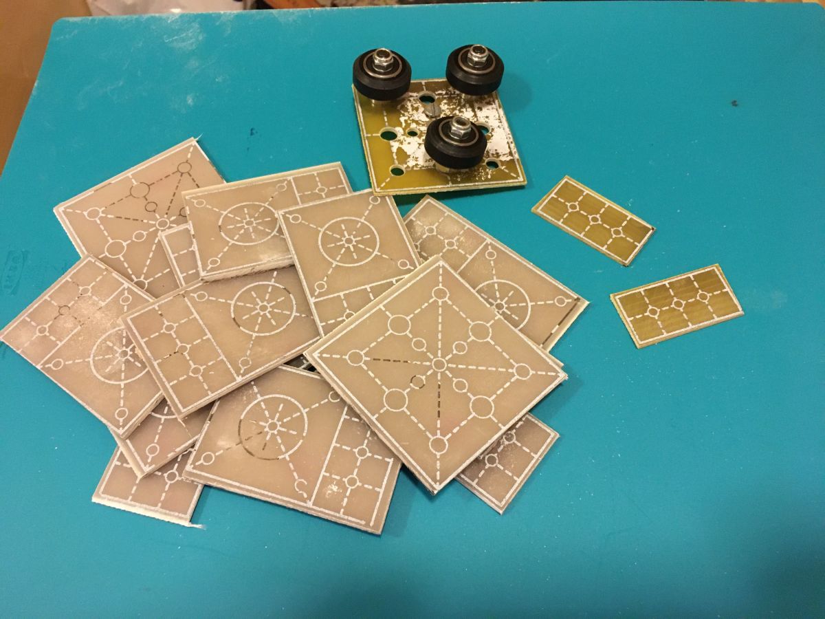
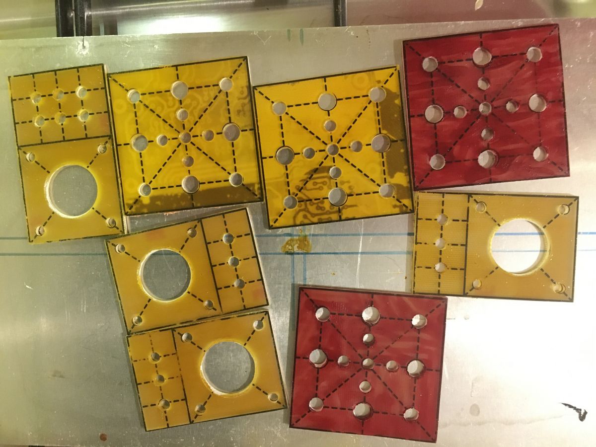
The design used a BigTreeTech SKR1.3 controller, TFT43 display, TMC2208 3.0 UART drivers, M8 threaded rods for Z, and FR4-made mounts and belt tensioners.
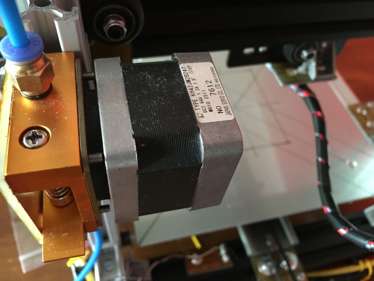
Core parts included an MK8 extruder and an E3D v6 hotend, while an early CD-ROM-drive concept was dropped as too limited.
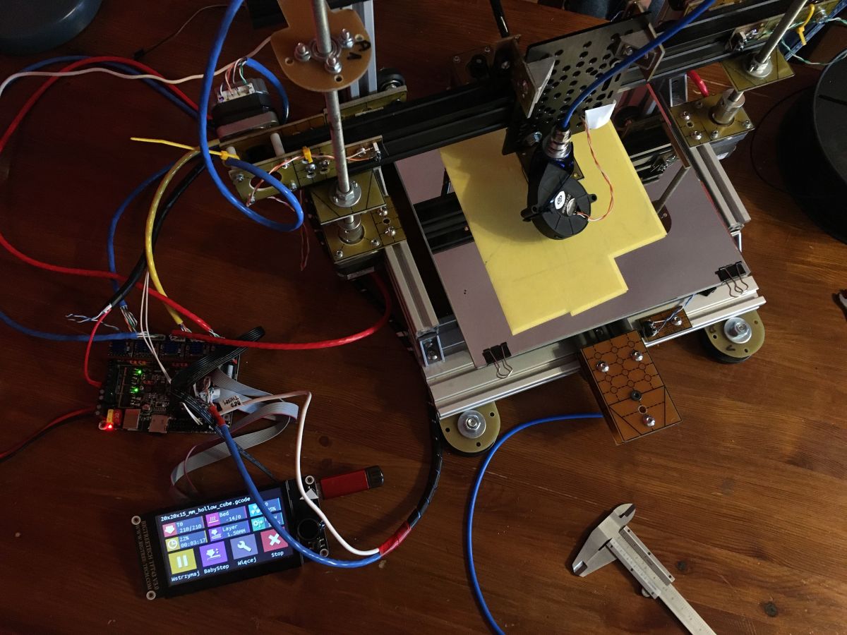
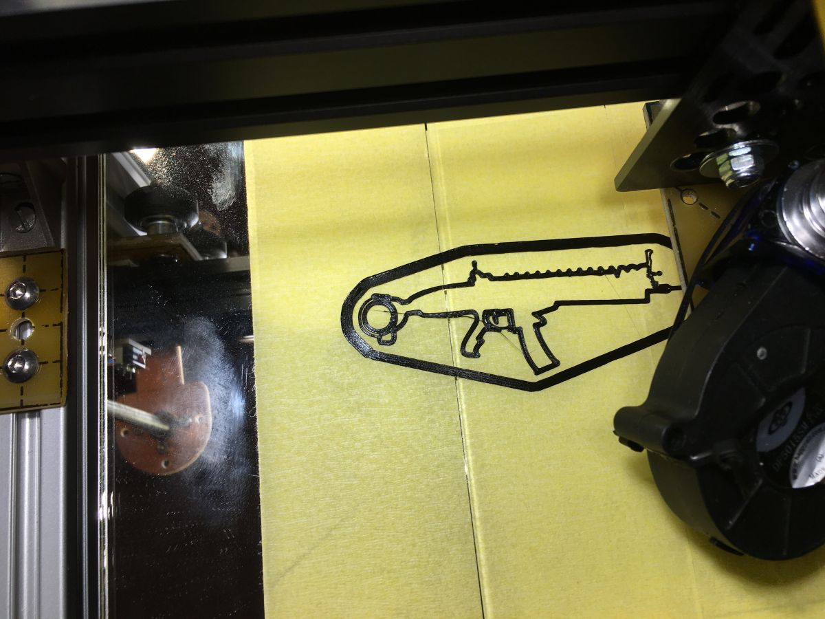
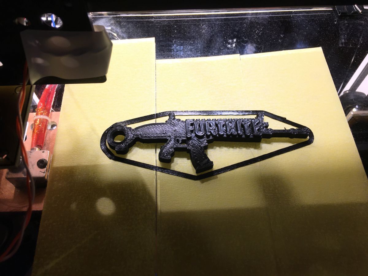
After quick calibration of the table, extruder, and Z-axis, the amateur prototype started working perfectly.
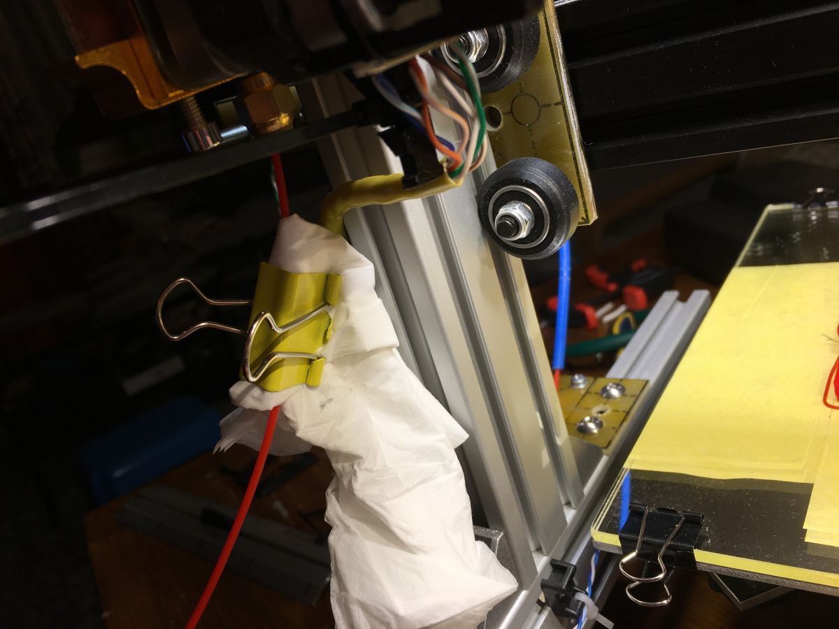
The first prints were made on a table with no cable tidying, and a primitive filament cleaner was added later from a tissue and paper clip.
Generated by the language model.
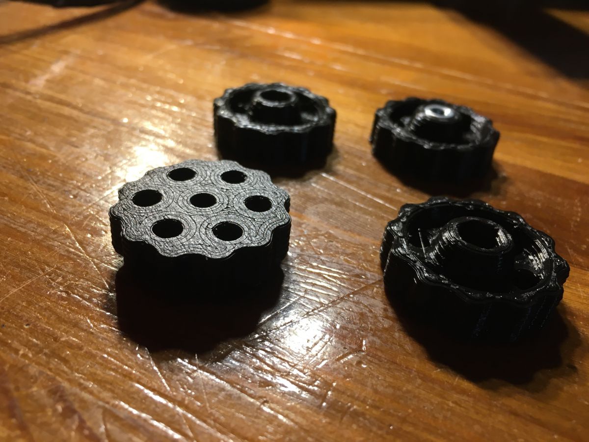
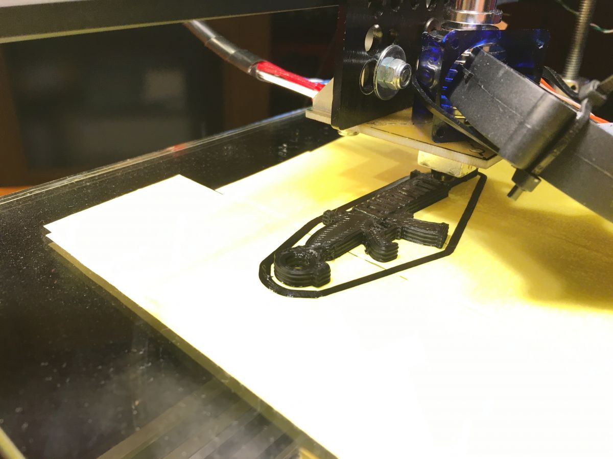
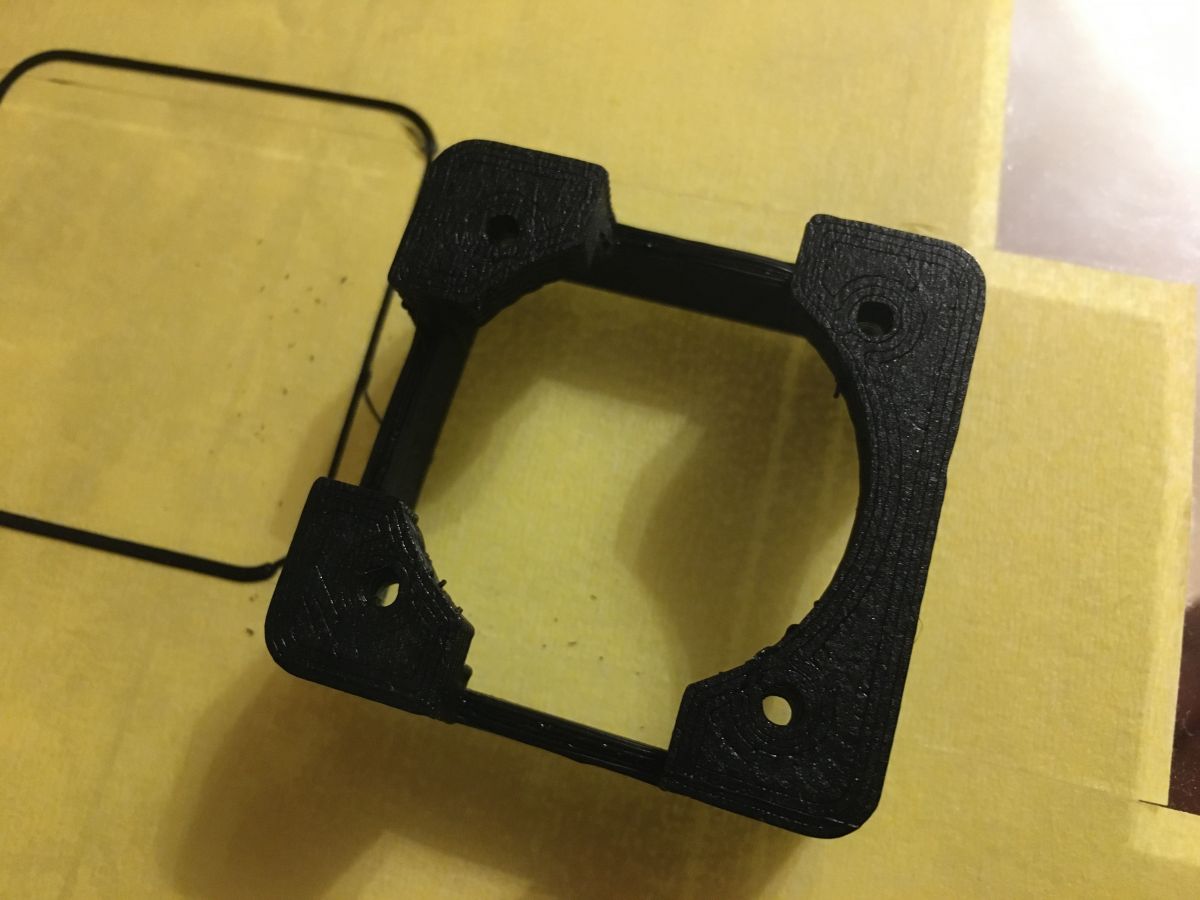
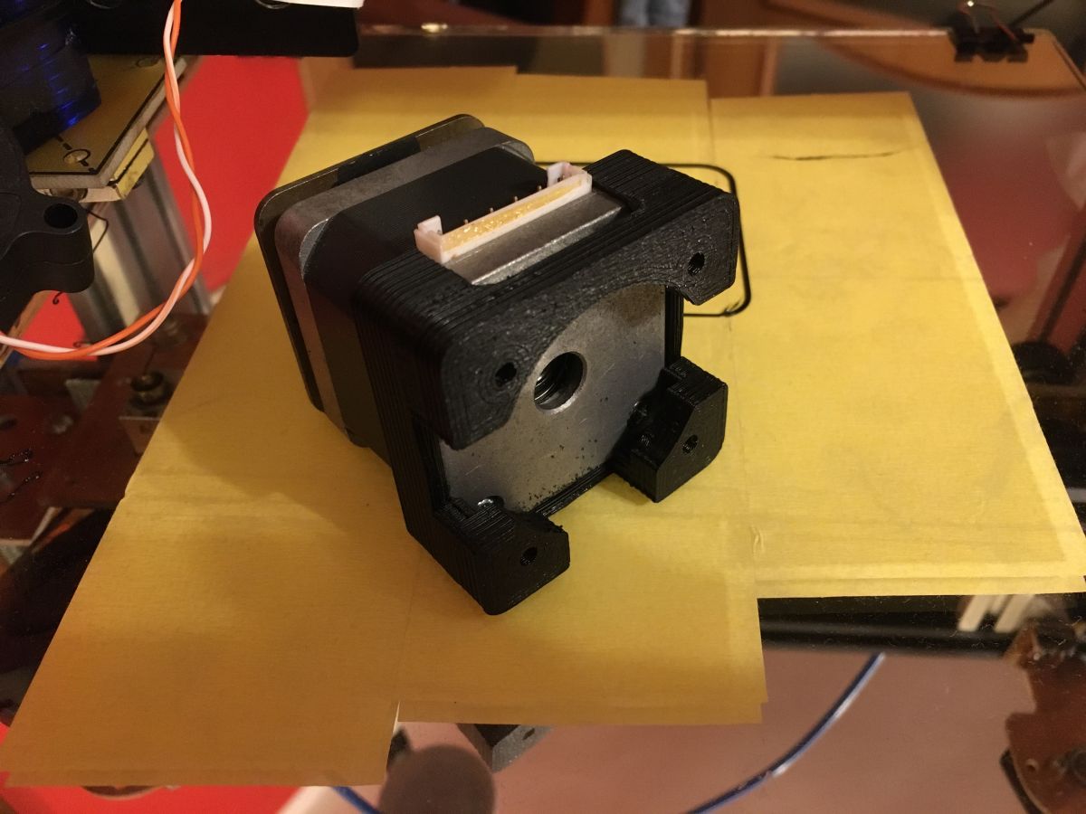
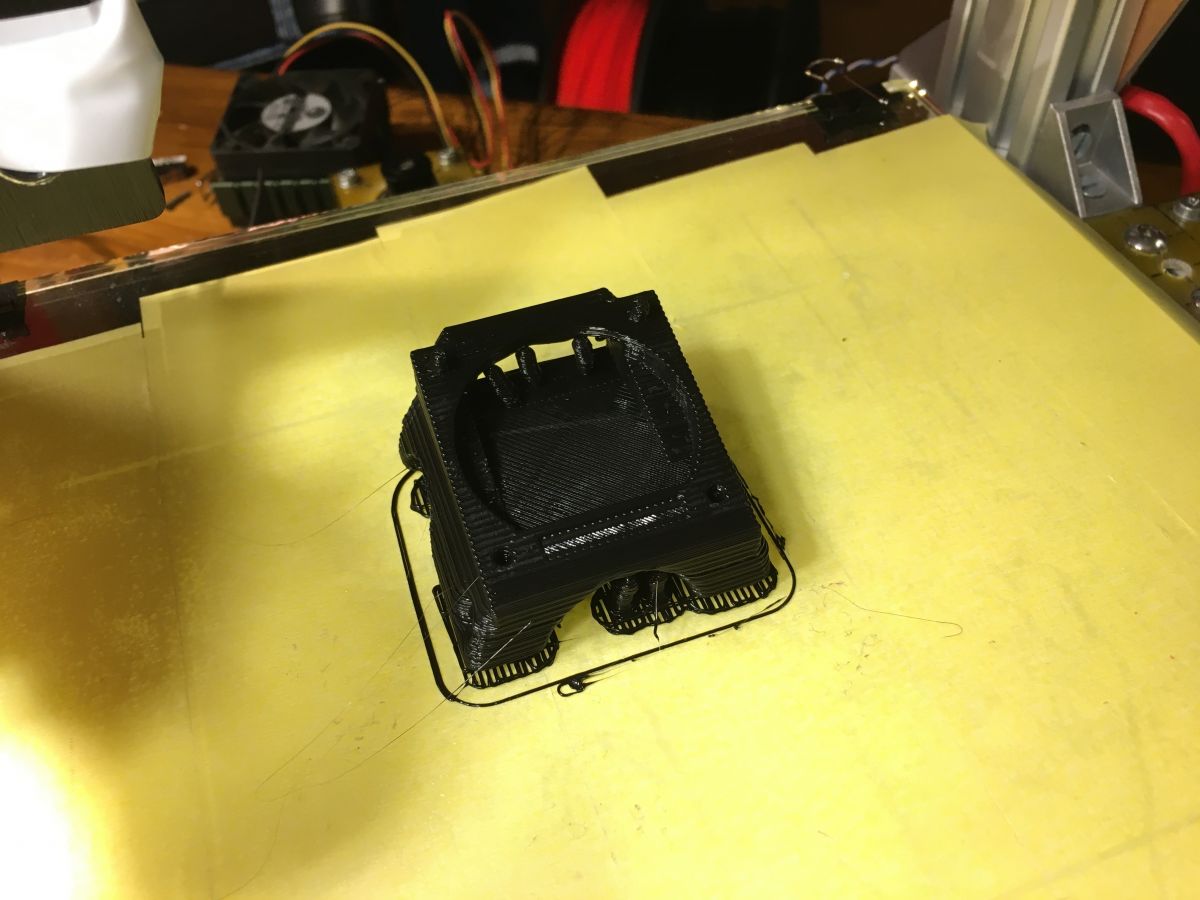
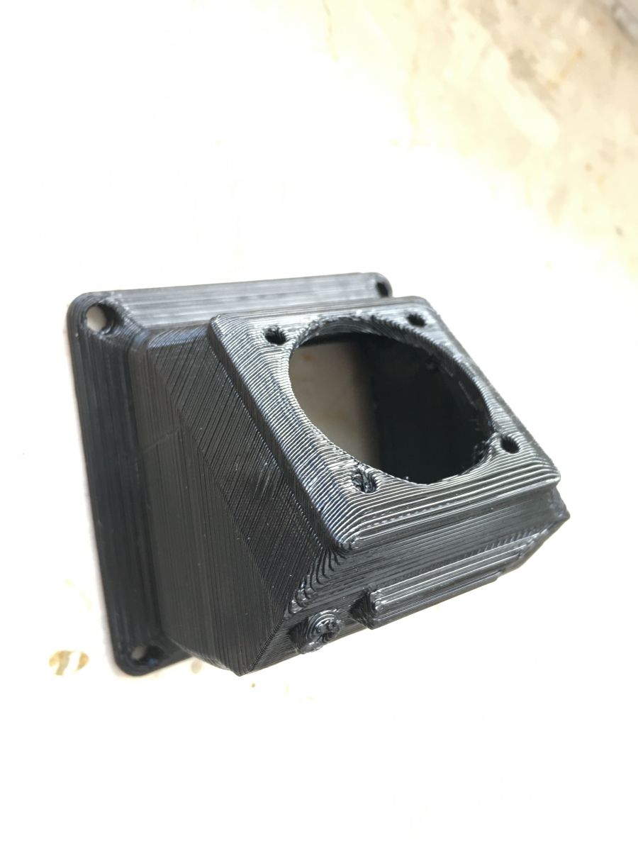
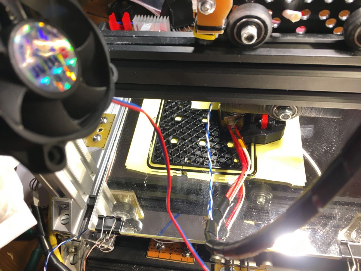
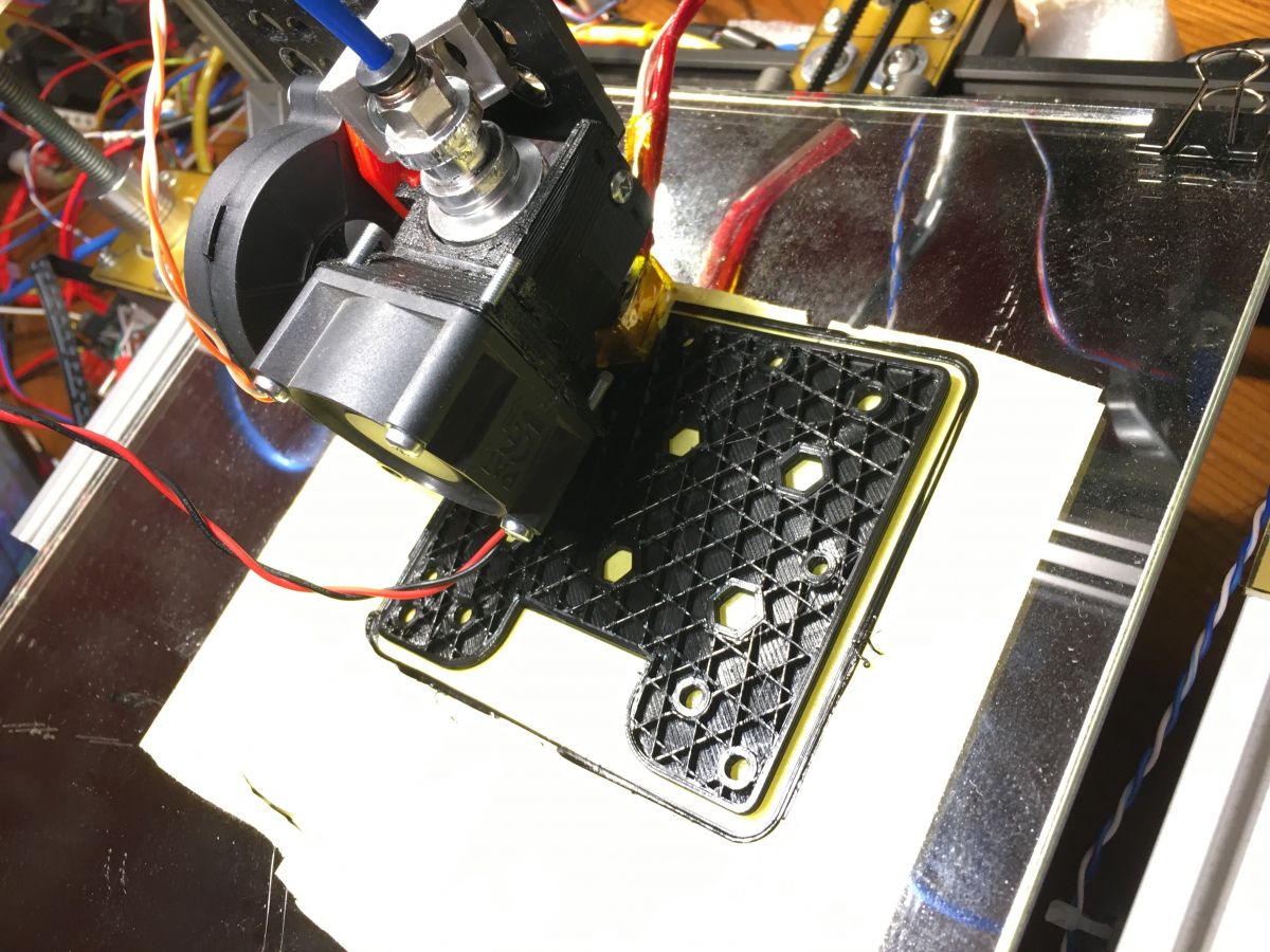
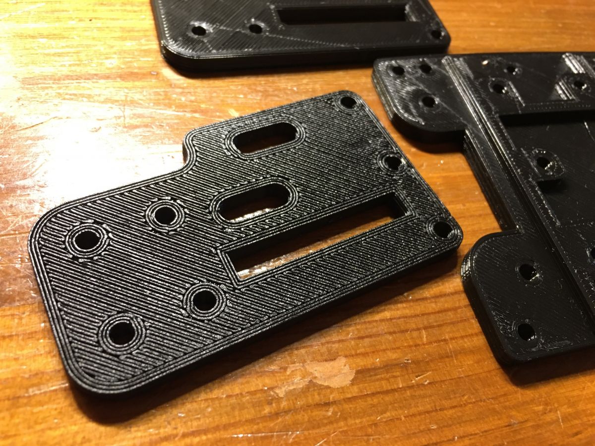
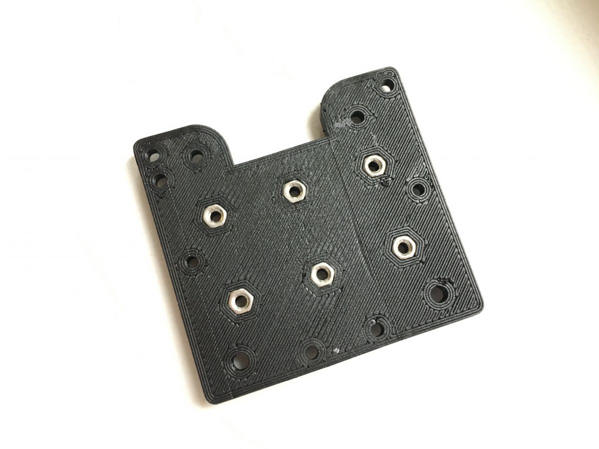
The 3D printer is a subject that has interested me for a long time. I thought my own 3D printer was completely out of my reach, until I had my first exposure to an Anycubic Photon resin printer that I got for repair. Once the equipment was up and running I was able to play around with printing. I went nuts However, the time to print a part took too long for me, so I became interested in the subject of filament printers. I had a couple of T2040 and v-slot profiles in stock with rollers and gantry plates, so I set about bolting them together. I also had a 'sample' linear guide with carriage from IGUS-this was my Y-axis. I purchased a BigTreeTech SKR1.3 controller with TFT43 display and TMC2208 3.0 UART motor drivers. The stepper motors had been lying in my cupboard for a few years. Now they have come in handy. For the Z-axis I used M8 threaded rods (ordinary, rolled ones from the market). I made all the necessary motor mounts, belt tensioners (and more) from FR4 2mm laminate. I bought an MK8 extruder and a HOTEND E3D v6 and a few small things and after a few days the launch took place. I should add that I had originally thought of an experimental design based on old CD-ROM drives, but I now know that this would have been pointless due to the very slim possibilities. The printer, after a quick calibration of the table, extruder and Z-axis, started working perfectly immediately (perfectly for an amateur design built "on the knee"). Today this machine is in the process of being expanded, on components printed by itself but I would like to present what was then created driven by dreams. At the time, as it was a prototype, I didn't think about tidying up the cables - I put everything together on a table and the first prints were created under these conditions.
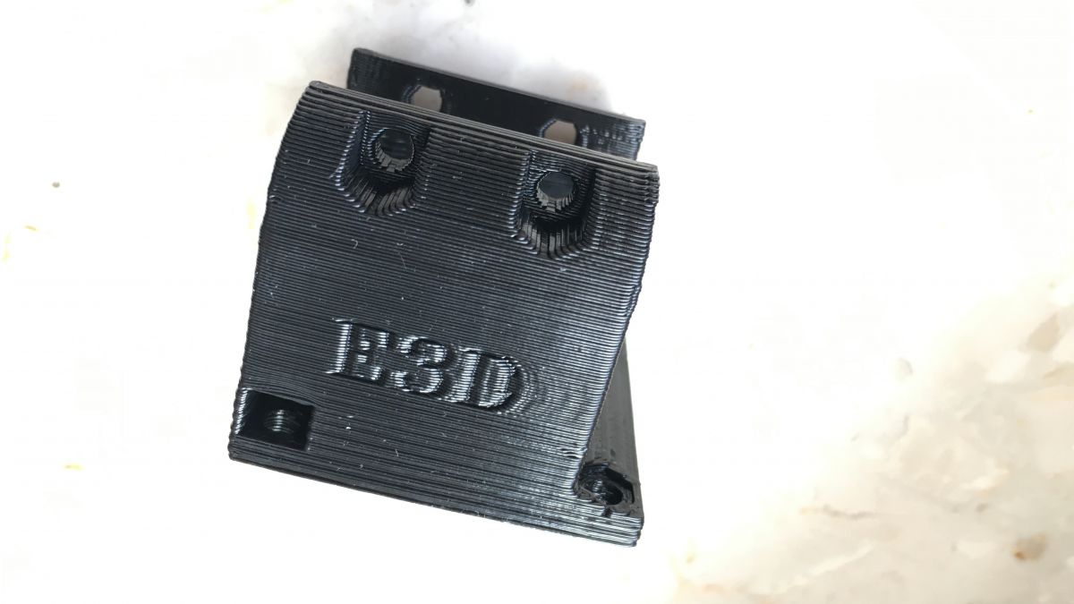
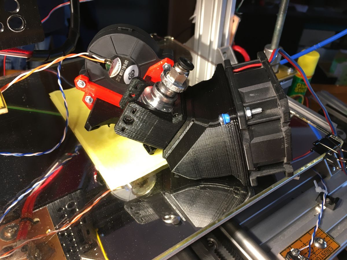
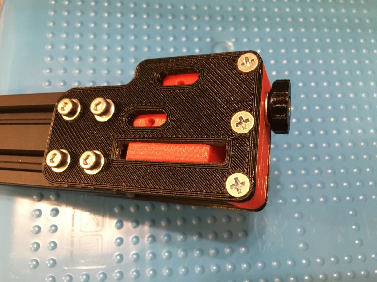
edit: some more photos:
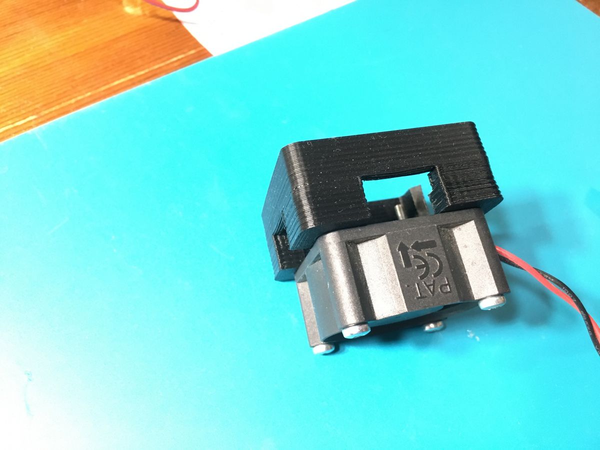
i made a primitive filament cleaner out of a tissue and clipped it with a paper clip
About Author
Bobo[PL] wrote 150 posts with
rating 353 , helped 2 times.
Live in city Zabrze.
Been with us since 2006 year.
Bravo for your self-denial in creating your device.
What kind of working area did you come up with?
Think about replacing the screws with trapezoidal ones. [Read more]
Bobo[PL]
28 Oct 2020 09:48
Thanks 🙂
Although the table was 235x235mm the range of movement was limited to 150x200mm. [Read more]
Tomekob
28 Oct 2020 10:54
Super! I started with the Anet A8 and only today I see that a printer comparable to the Anet can be assembled in-house, I think with much better results. The pain of my Anet is the levelling of the table.... [Read more]
Bobo[PL]
28 Oct 2020 22:28
I do the levelling "on a piece of paper". I do this with the table and nozzle warmed up to operating temperature.
Exactly. My guide is also so short :) But I later replaced the guide with linear... [Read more]
zulugula
29 Oct 2020 06:56
I also had a sensor of my own design in my folding machine, now it levels on a paragon (0.05)mm and nothing more is needed.
Show me your prints, how do the layers come out at the gw bar? On the z-axis?
And... [Read more]
HandMade
29 Oct 2020 14:08
For the price of the Anet you won't build anything that prints like it. The control chip of the colleague in this thread is more expensive than the whole Anet.
To the author of the topic: the use of... [Read more]
Tomekob
29 Oct 2020 18:03
Oj HandMade I have the impression that the author wrote that this is a prototype version built "on the knee" and there are pictures of that.
As for my Aneta I am not concerned with building a cheaper... [Read more]
Bobo[PL]
29 Oct 2020 21:35
Of course, I had to calibrate the Z-axis movement. I established an initial reference point and used the controller to raise the Z-axis by a few cm and then measured with a calliper by how much the height... [Read more]
zulugula
29 Oct 2020 21:50
I see it is not that, what nozzle because I think it is big, what height of layer? Did you have any problems with the sliders? I read that they must be quite accurately set because they jam. I took 4 pieces... [Read more]
andrzejlisek
29 Oct 2020 22:05
Very nice, there's nothing like the satisfaction of building a rather complex device with your own hands.
Looking at the pictures of some of the components that are made as 3D printing, one can come... [Read more]
zulugula
29 Oct 2020 23:02
Buy the printer...print the printer and return the printer :) [Read more]
LA72
29 Oct 2020 23:10
A 3D printer is not just about plastics.
In the case of Prusa and its clones, one printer makes another.
What remains are the electronics and mechanical parts. [Read more]
FAQ
TL;DR: A DIY FFF printer ran on Marlin 2.0 with SKR1.3+TMC2208, and the control bundle cost 127.71 PLN; the builder "measured with a calliper" to dial Z-steps. [Elektroda, Bobo[PL], post #19008176]
Why it matters: This FAQ helps new builders decide parts, setup, and quick fixes for a first successful DIY printer.
Adhesion/cooling: UHU or cheap glue on mirror; insulate hotend with cotton pad + Kapton after adding part cooling. [Elektroda, Bobo[PL], post #19006427]
What parts did the DIY printer use to get printing fast?
The build used T-slot profiles, IGUS sample guide (later rollers), MK8 extruder, E3D v6 hotend, SKR1.3 with TMC2208, and TFT43. It ran quickly after basic table, extruder, and Z calibration. Mounts and tensioners were cut from 2 mm FR4 laminate. [Elektroda, Bobo[PL], post #19004381]
What print area did the prototype achieve and why was it limited?
The bed measured 235×235 mm, but usable travel was about 150×200 mm. Early mechanics and guide choices constrained motion until later upgrades. [Elektroda, Bobo[PL], post #19004865]
How do I level the bed without a sensor?
Heat the nozzle and bed to printing temps. Use a sheet of paper under the nozzle to adjust corners until you feel slight drag. Re-check after the first layer. The builder said he levels "on a piece of paper." [Elektroda, Bobo[PL], post #19006427]
Any quick alternative to a feeler gauge for consistent Z-offset?
Yes. One user levels using a receipt that’s about 0.05 mm thick. It acts like a thin shim for repeatable nozzle gap. This helps standardize first layers. [Elektroda, zulugula, post #19006668]
My inductive probe hates glass. What gives?
A member reported inductive sensors struggled on glass, and even BLTouch needed attention. Expect unreliable triggering unless you add a metal target under glass or switch methods. "Still that first layer needs a lot of attention." [Elektroda, Tomekob, post #19004974]
Should I replace M8 Z-rods with trapezoidal screws?
Community advice: replace ordinary rolled M8 rods with trapezoidal screws for smoother Z motion and fewer banding artifacts. This improves layer consistency and reliability. [Elektroda, LA72, post #19004814]
How do I calibrate Z steps per mm on a fresh build?
Use the builder’s method:
Set a reference Z=0, then command a several‑cm lift.
Start with painter’s tape if needed. For glass, apply a glue stick; UHU gave the best adhesion, but a cheap market stick also worked. Clean the mirror and reapply as needed. [Elektroda, Bobo[PL], post #19006427]
How can I unlock the full bed area if a short guide limits travel?
Replace the short sample guide with linear rollers while keeping the carriage. This change allowed full table use on the featured build. [Elektroda, Bobo[PL], post #19006427]
Do I need to insulate the hotend after adding part cooling?
Yes. After adding a filament/part cooling fan, insulate the heater block. A cotton pad wrapped with Kapton tape stabilized temperatures and improved results. [Elektroda, Bobo[PL], post #19006427]
What electronics and firmware combo proved cost‑effective?
BigTreeTech SKR V1.3 with five TMC2208 UART drivers and a TFT43 ran Marlin 2.0 well. Reported prices: TFT43 V3.0 127.76 PLN; SKR V1.3+TMC2208 set 127.71 PLN. [Elektroda, Bobo[PL], post #19008176]
Why switch from resin (Anycubic Photon) to a filament printer?
The builder found resin parts took too long to print. Filament printing offered quicker iteration for larger functional components and easier experimentation. [Elektroda, Bobo[PL], post #19004381]
How short should I keep the Bowden tube?
Keep the Bowden as short as your layout allows. A member advised shortening it to reduce slack and improve extrusion response and retraction accuracy. [Elektroda, zulugula, post #19006668]
What community improvements were suggested for this prototype?
Feedback highlighted: upgrade Z shafts, shorten Bowden, plan electronics mounting and cable management, improve part cooling, and optimize X belt locking and mass. Also noted a limited working area. [Elektroda, HandMade, post #19007300]
Any gotchas or failure modes to watch for on first layers?
Expect first‑layer issues if probing on glass with inductive sensors or if the hotend runs cold due to fan blast. Insulate the block and consider manual leveling for reliability. [Elektroda, Tomekob, post #19004974]


Comments
Bravo for your self-denial in creating your device. What kind of working area did you come up with? Think about replacing the screws with trapezoidal ones. [Read more]
Thanks 🙂 Although the table was 235x235mm the range of movement was limited to 150x200mm. [Read more]
Super! I started with the Anet A8 and only today I see that a printer comparable to the Anet can be assembled in-house, I think with much better results. The pain of my Anet is the levelling of the table.... [Read more]
I do the levelling "on a piece of paper". I do this with the table and nozzle warmed up to operating temperature. Exactly. My guide is also so short :) But I later replaced the guide with linear... [Read more]
I also had a sensor of my own design in my folding machine, now it levels on a paragon (0.05)mm and nothing more is needed. Show me your prints, how do the layers come out at the gw bar? On the z-axis? And... [Read more]
For the price of the Anet you won't build anything that prints like it. The control chip of the colleague in this thread is more expensive than the whole Anet. To the author of the topic: the use of... [Read more]
Oj HandMade I have the impression that the author wrote that this is a prototype version built "on the knee" and there are pictures of that. As for my Aneta I am not concerned with building a cheaper... [Read more]
Of course, I had to calibrate the Z-axis movement. I established an initial reference point and used the controller to raise the Z-axis by a few cm and then measured with a calliper by how much the height... [Read more]
I see it is not that, what nozzle because I think it is big, what height of layer? Did you have any problems with the sliders? I read that they must be quite accurately set because they jam. I took 4 pieces... [Read more]
Very nice, there's nothing like the satisfaction of building a rather complex device with your own hands. Looking at the pictures of some of the components that are made as 3D printing, one can come... [Read more]
Buy the printer...print the printer and return the printer :) [Read more]
A 3D printer is not just about plastics. In the case of Prusa and its clones, one printer makes another. What remains are the electronics and mechanical parts. [Read more]