This article describes building a programmable speed regulator for brushed DC motors that are low-noise, powerful and inexpensive. Changes in temperature, voltage or motor load do not impact the regulator. Moreover, this circuit is unaffected by the motor coil’s resistance, enabling several motors in the same application without needing adjustments.
Applications of brushed DC motors
Brushed DC motors are used in a wide range of applications, including:
• Electric tools: Brushed DC motors are commonly used in electric drills, screwdrivers and other power tools because they provide high torque and can be easily controlled.
• Household appliances: Brushed DC motors are used in vacuum cleaners, washing machines and other household appliances because they are reliable, cost-effective and easy to control.
• Automotive industry: Brushed DC motors are used in electric windows, windshield wipers and other automotive applications because they are durable and can operate under high temperatures.
• Robotics: Brushed DC motors are used in robotics and automation systems because they provide precise control and high torque, making them ideal for positioning and manipulation.
• Medical equipment: Brushed DC motors are used in medical equipment like surgical tools and prosthetic limbs because they provide reliable, precise control and can operate quietly.
• Industrial machinery: Brushed DC motors are used in conveyor systems, pumps and other industrial machinery because they provide high torque and can be easily controlled.
Although brushless DC motors are gradually replacing brushed DC motors in many applications due to their higher efficiency and reliability, brushed DC motors continue to be widely used in many industries due to their simplicity, cost-effectiveness and versatility.
The proposed design
The proposed circuit is designed primarily for appliances that use small, brushed DC motors and need consistent motor speed and low noise. Although the motor speed can be changed via the I2C interface, it is already pre-programmed and does not require trimming after installation.
This approach eliminates the need for a feedback sensor in speed regulator circuits by using the motor as the sensor instead. The motor coil resistance impacts other, more traditional designs. Both calls need post-production trimming. Applications that use audio, for example, are very noise-sensitive. Hence, any PWM-based motor controller is incorrect.
When brushes change from one coil to another in a brushed DC motor, interference is created. This is one of the greatest drawbacks of such a motor. It may interfere with nearby circuits using the same power source’s normal operation if it isn’t filtered. It is impossible to eliminate interference totally, but it is possible to reduce it using a capacitor linked in parallel to the motor (or, in rare situations, a ferrite coil in series).
In the instance of the design covered in this document, the motor speed is established using minor residual interference. Most of the time, brushed DC motors with low cost, low voltage and low power have three moving coils. Therefore, the frequency of the spikes is equal to 3× the rotor’s rotations because each causes interference in the form of spikes.
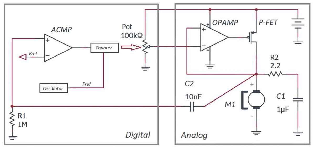
The speed can be calculated by counting the spikes, which can then be controlled by automatically changing to a pre-programmed value. The SLG47004 from Renesas, a flexible programmable mixed IC with only fundamental external components, can accomplish all this and more. Only one chip is utilized in this architecture. The SLG47004 IC’s compact 3 × 3-mm STQFN-24 package includes all required analog and digital macrocells. See the simplified schematic diagram in Figure 1 to comprehend how it functions.
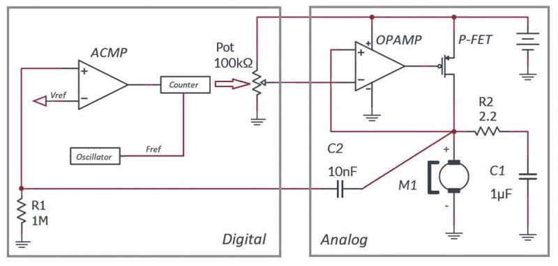 Figure 1: Simplified schematic diagram
The analog component comprises a straightforward voltage regulator with an output power P-channel MOSFET. However, it has a digital potentiometer managed by a digital component of the device rather than a voltage reference.
The ACMP, which detects the tiny spikes from motor brushes, makes up the digital portion. While blocking DC voltage, capacitor C2 allows the spikes to pass. These are then amplified to a VDD level and sent to the counter, configured to detect frequency, where the spike frequency is compared with an oscillator reference frequency.
The digital potentiometer’s resistance is set when the device is turned on. Thus, a little voltage is applied to the motor using a current amplifier (voltage regulator) made of an op-amp and a P-FET. Spikes start to appear as it begins to rotate. The digital potentiometer resistance will rise by one bit for each detected spike, gradually raising the motor voltage. The motor speed will increase until the reference and spike frequencies are equal. Whenever this occurs, the counter will send a signal to the potentiometer telling it to reduce its resistance by one bit every spike. The motor speed will decrease along with the voltage. The cycle continues once the counter notices the frequency reduction and instructs the potentiometer to raise its resistance.
In other words, when the spike frequency is lower than the reference frequency, the voltage on the motor increases and vice versa. The potentiometer will go up and down one step (1 LSB) after the motor speed has stabilized, maintaining the speed stability within 1 LSB. The ideal time to stabilize the motor speed is 1 LSB; however, due to inertia, it could take up to 50 LSB. The larger the motor load, the more LSB required to stabilize the speed.
Read the original article here.
After reading this article:
• What do you think of the proposed solution, which regulates the speed of a brushed DC motor using just one IC?
• Brushed DC motors are less expensive and require a simpler control than BLDC motors. Did you have a chance to work with both types of motors?

Comments