Making a DIY, "Poor Man's" LN882H development board with 7 segment display out of scrap
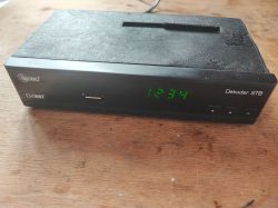
OpenBeken has been recently ported to LN882H platform, and I have received few such WiFi modules from our readers, so it was a good time to think about some kind of "dev board" for this new Lighting Semi platform. The modules I received were unfortunatelly not in TYWE3S/ESP12 format, so I was not able to just place them on NodeMCU, that's why I decided to take a slightly different path. And that path was.... an old sat tuner "hack"!
A typical LN882H module looks somewhat like this:
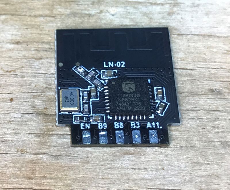
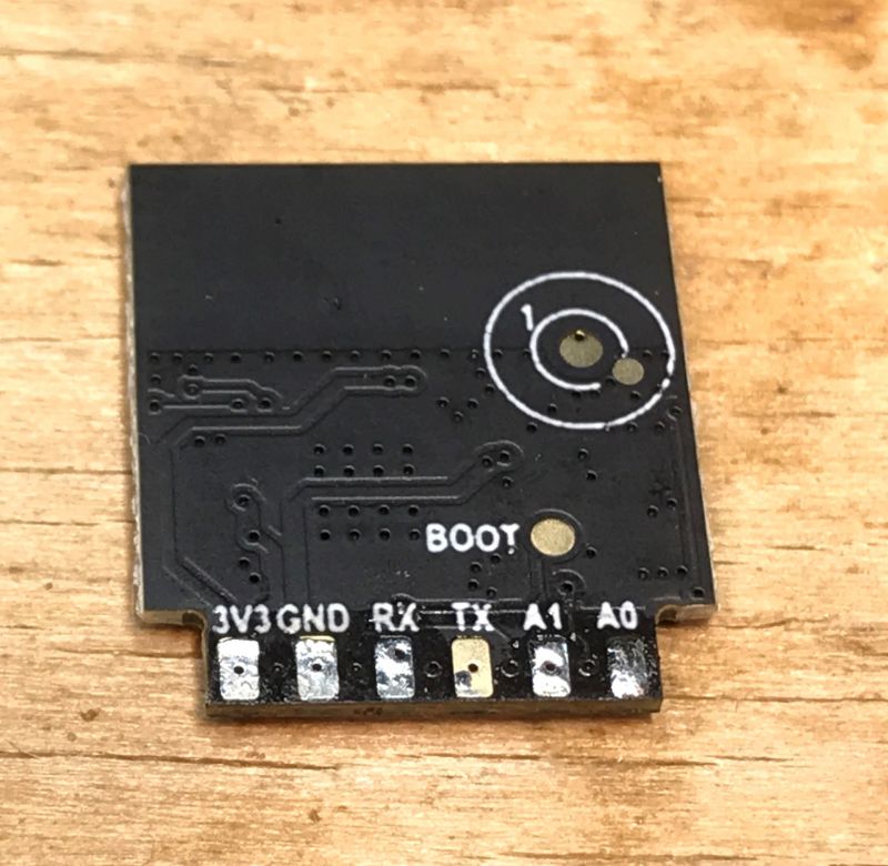
It requires only 3.3V to work, but for ease of development purposes, some extra peripherals like buttons can be also useful.
That's why I decided to use old sat tuner, the one that I have already described in the past, see related topics:
Running the HD2015 display/button controller after reverse engineering, comparison with TM1650
Salae 24MHz logic analyzer for 10$ - analysis of an unknown LED display protocol
My first step was to remove the not needed parts - I have removed RF and HDMI circuits. SCART will be also removed soon:
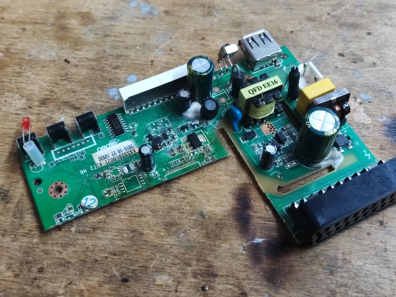
I have also removed the old MCU.
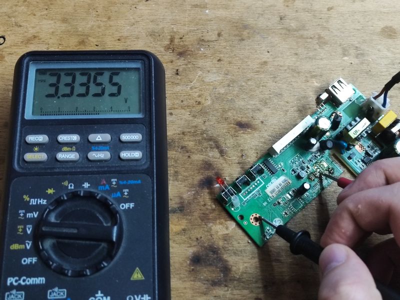
Then I checked if the board is still working. Of course, 3.3V is still present. This is good, because 3.3V willbe needed for WiFi module.
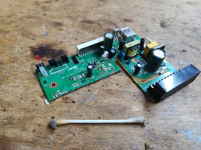
Cutting board is messy and may introduce some shorts, so extra caution is needed. I have also cleaned the board after desoldering.
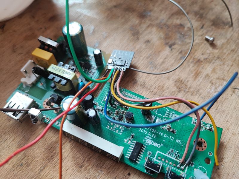
Finally, it was the time for some soldering. This step requires some patience. You also must be extra careful to avoid misconnecting the wires.
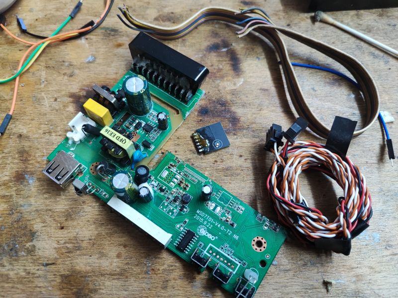
In my case, I decided to connect GND and 3.3V to the pads of old 1.8V LDO regulator, which I removed earlier. The 3.3V on this board comes from a step down converter, and step down is fed by 5V from main-powered flyback power supply.
So, soldering time:
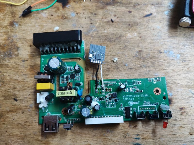
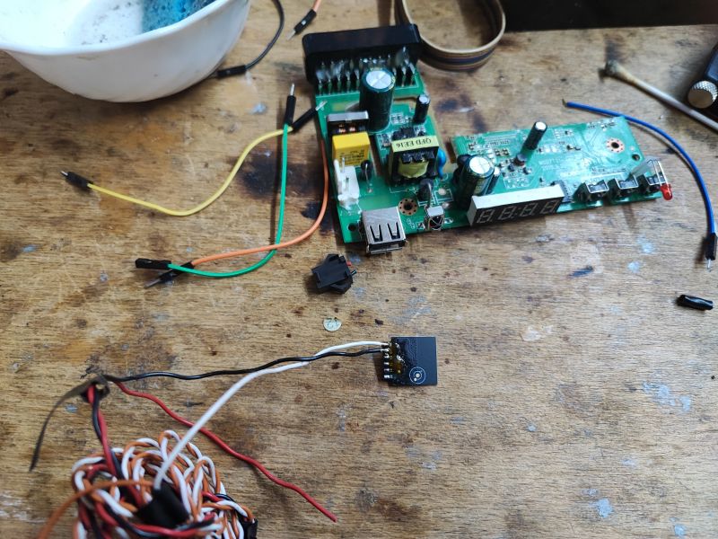
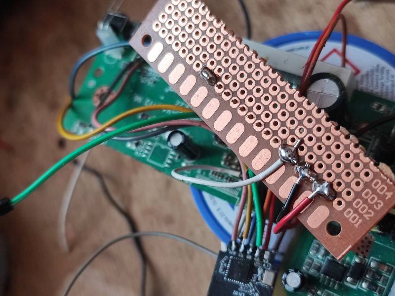
Using wire colors can help to remember their roles, white is 3.3V, black is ground.
Then I soldered wires to HD2015 7-segment LED display controller, which is already supported by OpenBeken:
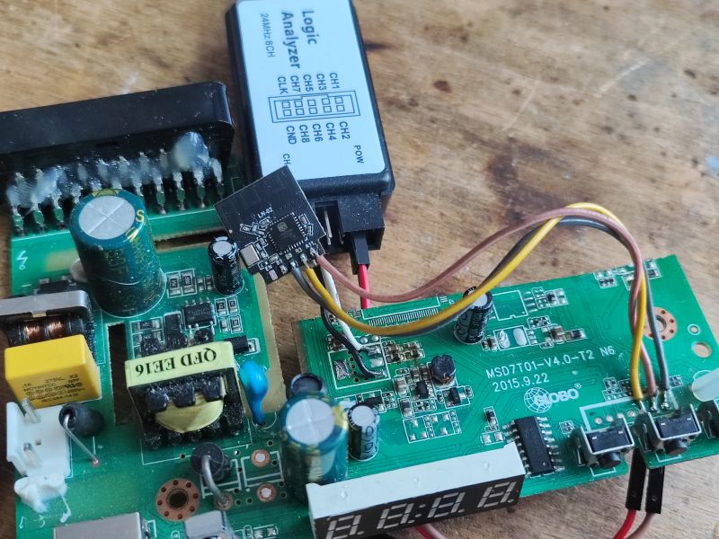
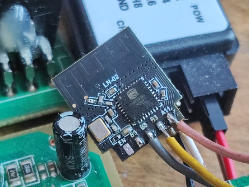
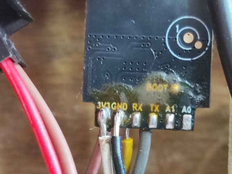
A quick test (after enabling necessary driver in OBK online build) has shown that it indeed works quite well:
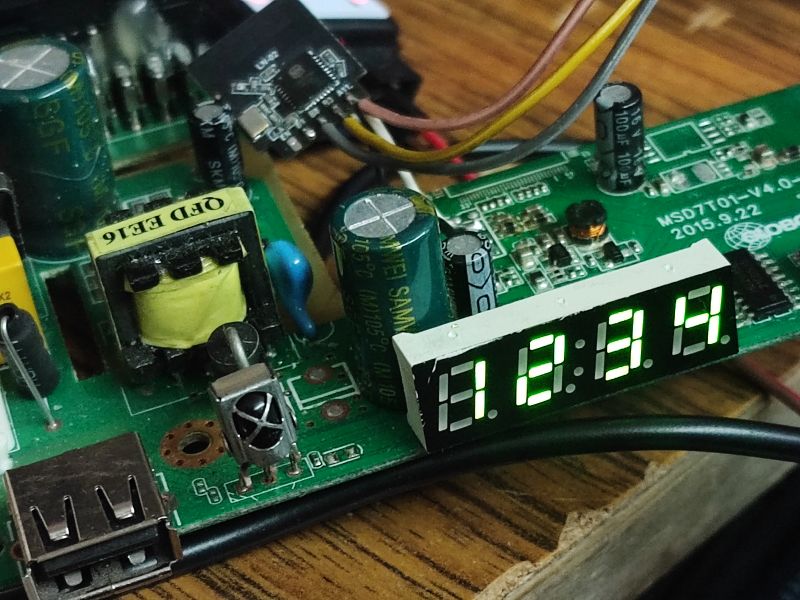
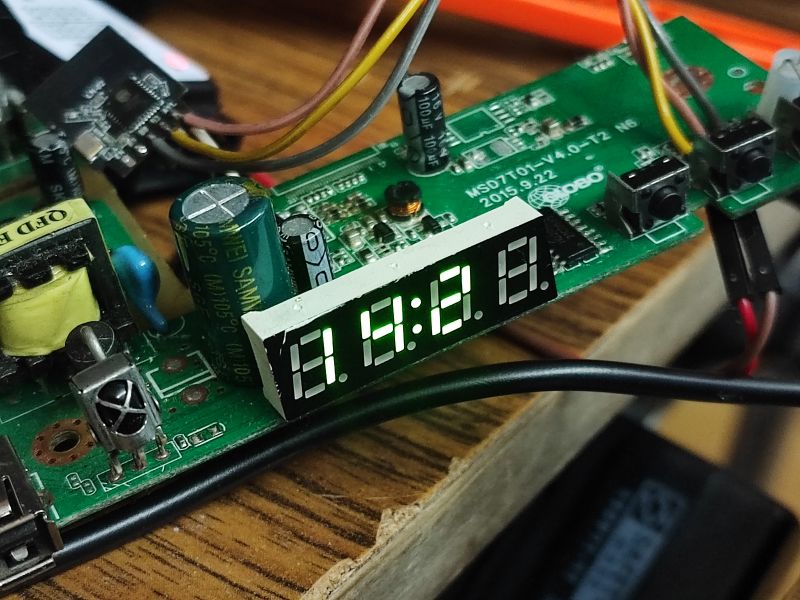
OBK provides an united "TMGN" driver for such displays, that can draw numbers and some letters:
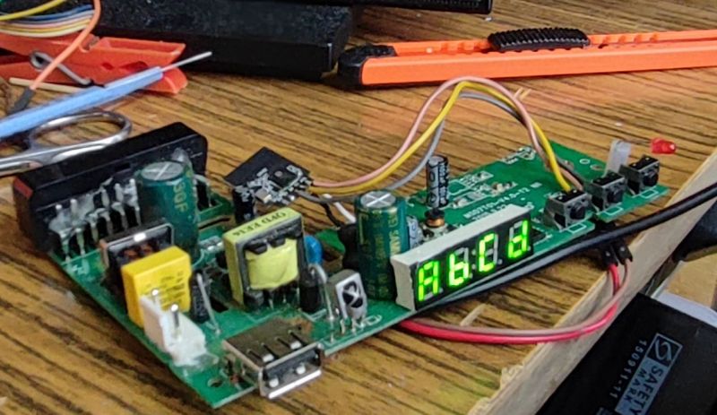
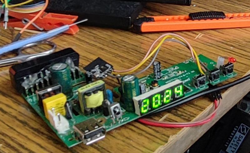
Display works, so it's time for the next part.
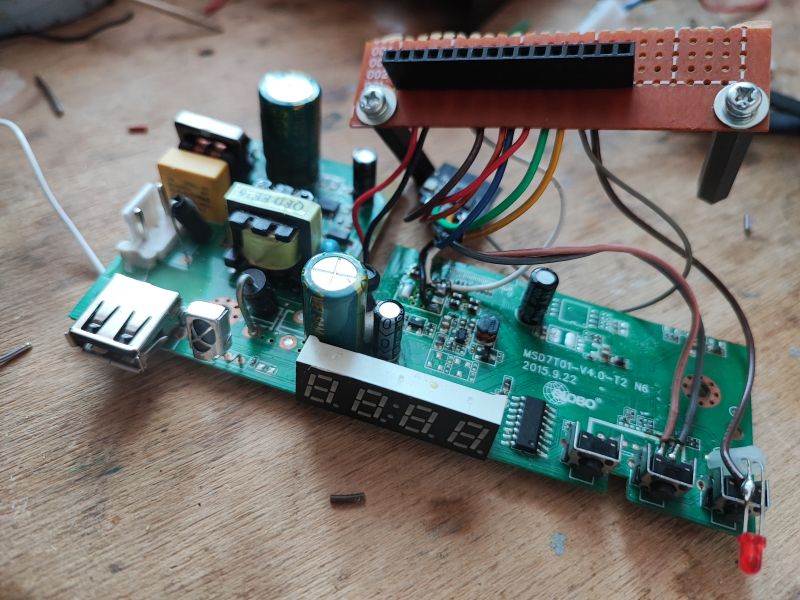
I have decided to also connect the IR receiver and extra LED, which is not controlled by HD2015:
Finally, I have routed the remaining pins out, to the female goldpin header:
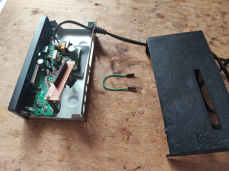
The last thing was to put everything together in the case. I couldn't use metal cover, it could have reduced the WiFi range. Futhermore it would be hard to cut that. That's why I have printed a replacement:
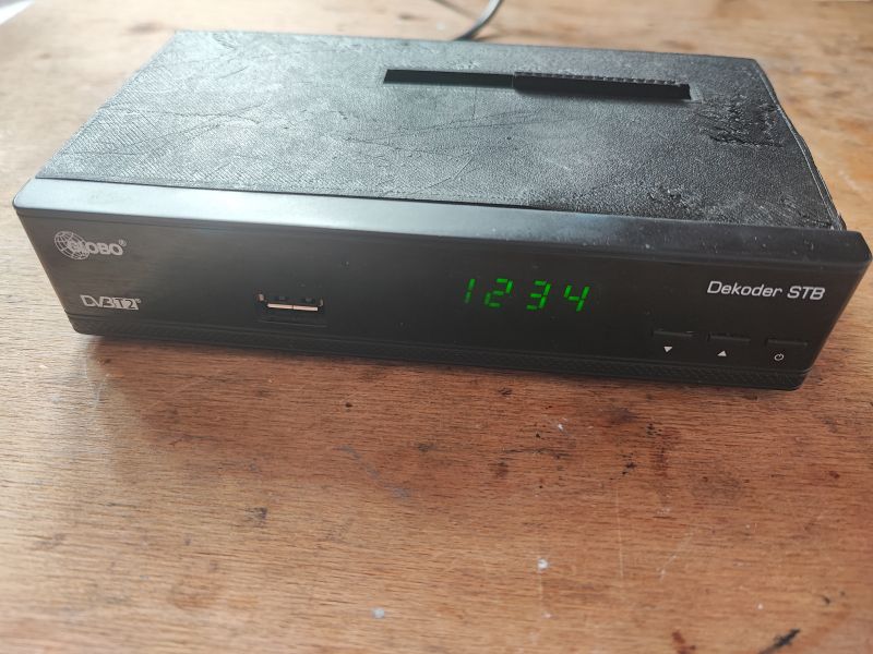
Of course, I have written down the GPIO of my new "dev board":
5V
5V
GND
GND
3.3V
3.3V
A0
TX
RX
A1
B9
B3
BOOT
LED
GND
GND
As you can see, all necessary flashing signals are routed out, but still, they should not be required. OTA works good on OpenLN882H. I have also routed out power (both 3.3V and 5V) and ground wires, and some of the GPIO.
I have already made some experiments with my new "dev board" and it works very well. Now I can easily test OpenLN882H, connect sensors like DHT11, BME280, shift registers, relays, potentiometers and much more. This is certainly more handy than just a bare TYWE2S-form module with no peripherals at all... and of course - it's possible to easily pair it with Home Assistant, thanks to OBK channels system.
Soon I may try to make some sample projects on that. Do you have any ideas what should I make? This display could be very useful...


Comments
How happy I am to get such cool ideas😀😀😀😀😀😀😀 [Read more]
You can also do the same with an Arduino, for example. You take an old piece of hardware, check how it works, and often it's not only the power supply that comes in handy, but also the display, buttons... [Read more]