PIC12F683 and SDCC - tutorial - how to create a simple dimmer (and read datasheets)
 .
.
In this topic I will build from scratch a simple LED dimmer controlled by two buttons. The project will be based on a PIC12F683, which I will program here without using external libraries - GPIO and PWM will be configured according to the information from the datasheet. For this I will select some external components from electrical junk so that my LED controller will be fully functional and work well with the 12V LED strip. Finally, I will solder everything together on a drilled prototype board.
This topic is somewhat related to my SDCC tutorial for the PIC18F2550, and I will be partly building on the steps described there:
Part 1 - Setting up the operating environment
https://www.elektroda.pl/rtvforum/topic3635522.html#18304424
Part 2 - Blink LED, IO pins, digital inputs and outputs
https://www.elektroda.pl/rtvforum/topic3647884.html#18389188
Part 3 - Oscillator settings. Internal oscillator, external oscillator, quartz resonator, PLL
https://www.elektroda.pl/rtvforum/topic3657704.html
Part 4 - Timers, interrupts
https://www.elektroda.pl/rtvforum/topic3676645.html#18580858
Part 5 - Operation of seven-segment display
https://www.elektroda.pl/rtvforum/topic3676650.html#18580877
Part 6 - MM5450 LED display driver
https://www.elektroda.pl/rtvforum/topic3845301.html
The table of contents will be completed as I write more parts.
What will the project cover? .
The tutorial/miniproject presented here will cover the following steps:
- booting the PIC12F from SDCC by operating directly on the PIC's registers
- configuring the PWM used to control the brightness of the LEDs in this way
- selecting and connecting a transistor to control the entire strip, not just one LED
- example soldering of the whole circuit on a drilled prototype board
By the way, let's see how this whole magic PWM works and looks on an oscilloscope.
Selected MCU and programmer connection .
This time the choice was the PIC12F683 - a small 8-bit MCU in a DIP08 chassis running on 5V, offering 6 GPIOs, 2048 Flash words, 128 SRAM bytes and 256 EEPROM bytes.
 .
.
It is programmed in a similar way to the PIC18F2550. I just happened to have a PICKIT2 on hand, although it could also be a clone:
Simple PICKIT2 clone (PIC programmer on USB). from readily available components .
The MCLR, power supply, PGD and PGC need to be connected:
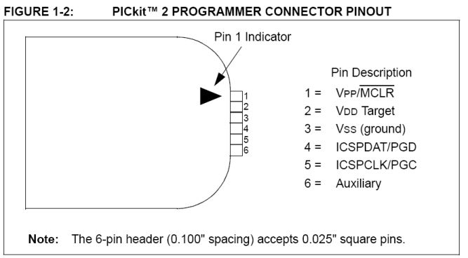 .
.
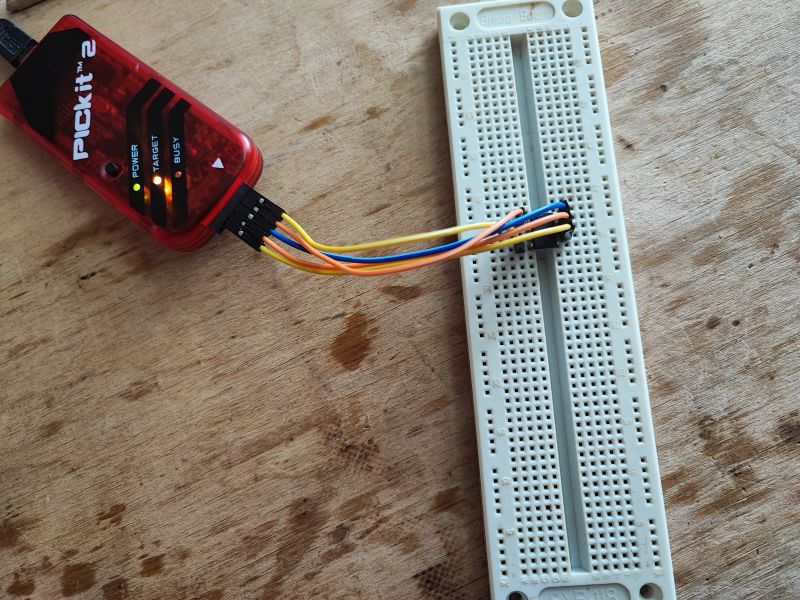
Completed connection:
 .
.
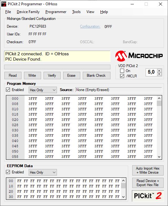
At first I ran the PICKIT2 program but the programmer was not seen - it turned out to be the culprit mouse , which I had to rewire to another USB port. Then it just started up:
 .
.
Minimum connection required .
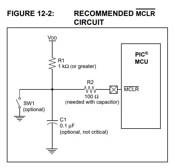
The programmer already sees the PIC, but did we forget something? Definitely about power supply decoupling - some 100nF ceramic capacitor between ground and power supply is useful. Without it, the MCU can operate unstably and unpredictably. But that's not all:
 .
.
You still need a 1k (or larger) resistor on the MCLR (a.k.a. RESET) pin. Without this, the PIC will not start, although the programmer will see it.
First program .
Now it's time to run some software. Everything as in the tutorial about the 18F2550:
Tutorial PIC18F2550 + SDCC - Part 2 - Blink LED, IO pins, inputs and outputs .
We take the blink under the PIC18F2550 and rewrite it. You need to include the appropriate header from here:
https://github.com/pfalcon-mirrors/sdcc/blob/master/device/non-free/include/pic14
This can be done directly:
Code: C / C++
or automatically:
Code: C / C++
The pic16regs.h header simply checks with the preprocessor what type of layout we have defined and attaches its registers for us, this can be previewed here:
https://github.com/pfalcon-mirrors/sdcc/blob/master/device/include/pic14/pic16regs.h
Let's assume we just want to blink the LED.
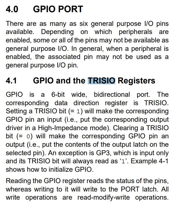
We look at the datasheet - here we do not have separate A, B, etc. ports like in the PIC18F2550, so there is no TRIS, TRISB, etc. register.
There is simply TRISIO and GPIO:
 .
.
A lit bit in TRISIO makes that pin an input, while a turned off bit means an output. So we want to write zeros there. And then we're going to manipulate the GPIO register to sequentially set the low and high states on the pins.
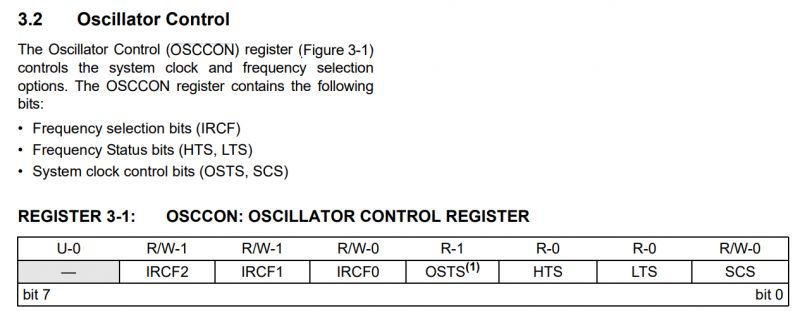
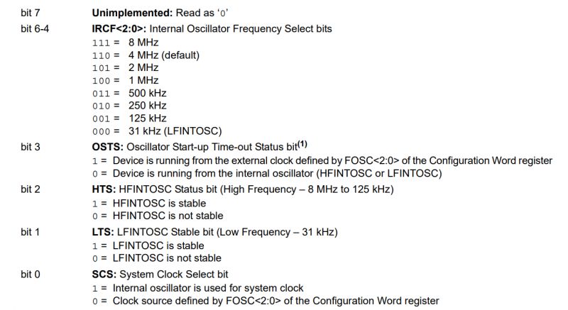
We still need to configure the internal oscillator - we don't need an external one. This is again the responsibility of OSCCON:
 .
.
 .
.
As a test, I entered 0x71 there, which is binary 0b01110001 - looking above this is the 8MHz IRFC and enabled Internal oscillator is used for system clock .
Code: C / C++
Still missing the wait - I didn't want to count how much it was in ms, so I called the function delay_smth. This function simply executes nop commands in a loop, essentially 'wasting' CPU time. As simple as possible:
Code: C / C++
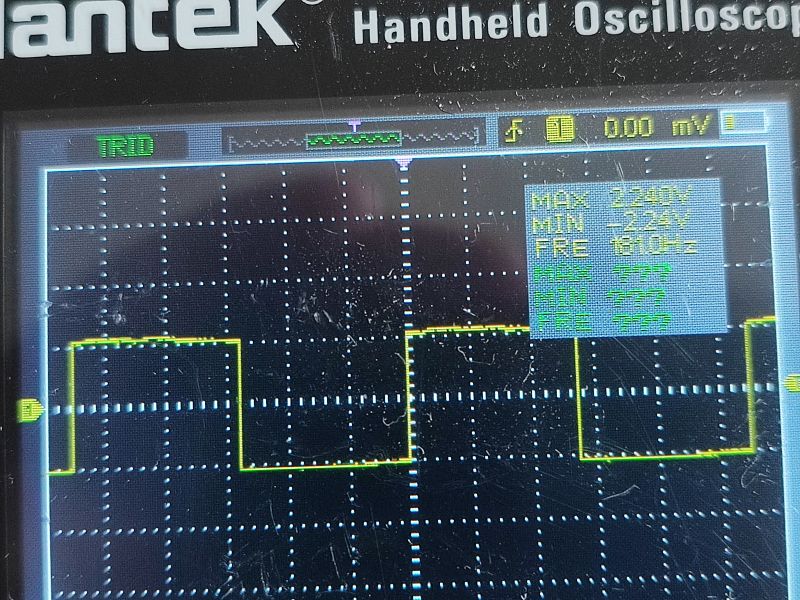
I connected an oscilloscope to the GPIO to check that the program works:
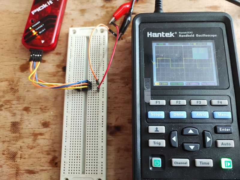
181Hz - meaning something is blinking, but fast. I'm not going to correct it here though.
 .
.
We start PWM .
I haven't corrected "pin waving" because we don't need it - we have hardware PWM here. PWM stands for Pulse Width Modulation, or pulse width modulation. In simple terms, PWM allows us to set the frequency and fill of a rectangular signal at a specific output of the PIC. To control the brightness of LEDs, a frequency of 1kHz is often adopted, while the fill of this signal varies depending on what brightness level we want. That is, we are essentially rapidly turning the LEDs on and off those 1000 times per second to get the desired brightness.
In this PIC, the PWM can only have an output to one selected pin:
 .
.
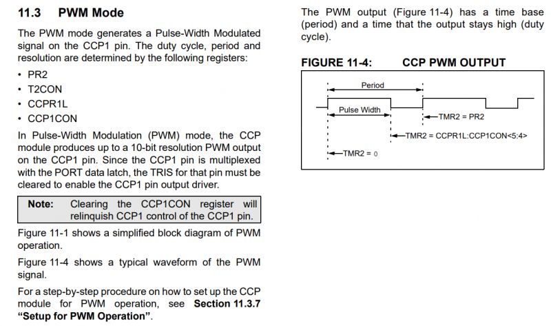
Refer to the relevant section of the datasheet note:
 .
.
A lot of these registers are... PR2, T2CON, CCPR1L, CCP1CON.... AND let's not forget to set the output mode for the PWM pin on the TRISIO.
Contrary to what you might think, however, this is not that difficult.
PR2 is basically the number of clock cycles (after using the prescaler/postscaler) that determines the PWM frequency.
CCPR1L is the number of cycles in which the signal is in the high state (followed by a switch to the low state). So if we have PR2 = 40 and we want a fill of 50% then CCPR1L is set to 20, and if we want a fill of 75% then CCPR1L should be 30.
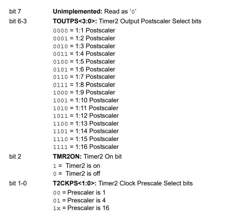
That leaves T2CON:
 .
.
 .
.
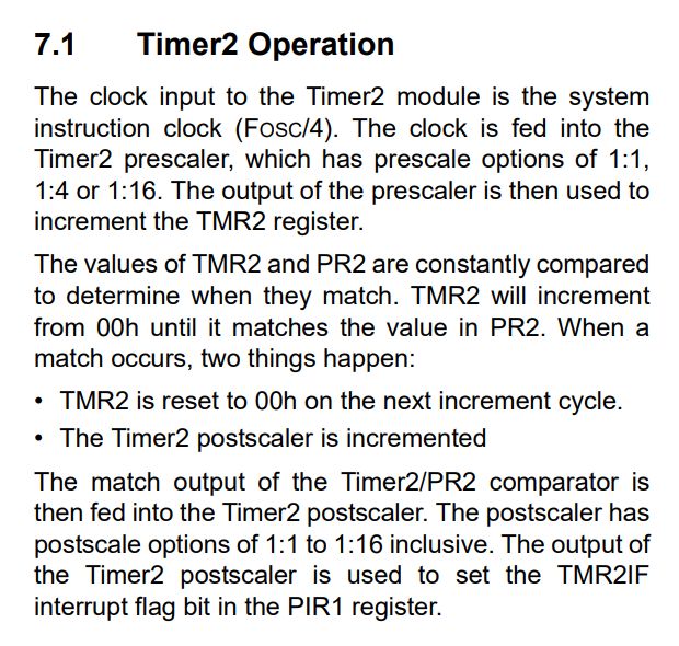
In T2CON, we set the poscaler and prescaler and switch on the timer. This timer (timer 2) will be used by the PWM. One more question is what these "scalers" scale. - Their input is the main clock of the Fosc/4:
 .
.
That is, we have to select the prescaler/postscaler so that we can then select the PR2 value corresponding to 1kHz .
Since Fosc is 4MHz, then Fosc/4 is 1MHz. A frequency of 1MHz corresponds to a period of 0.001ms. If we use a 1:4 prescaler:
Code: C / C++
This then increases Timer2 by 1 every 0.004ms.
To how many then must we count Timer2 to have 1kHz?
1kHz is a period of 1ms.
1ms divided by 0.004ms gives us 250.
0xFA is 250, so we need to enter 0xFA into PR2.
That still leaves CCPR1L - there we will enter 0 to 0xFA to vary the signal fill.
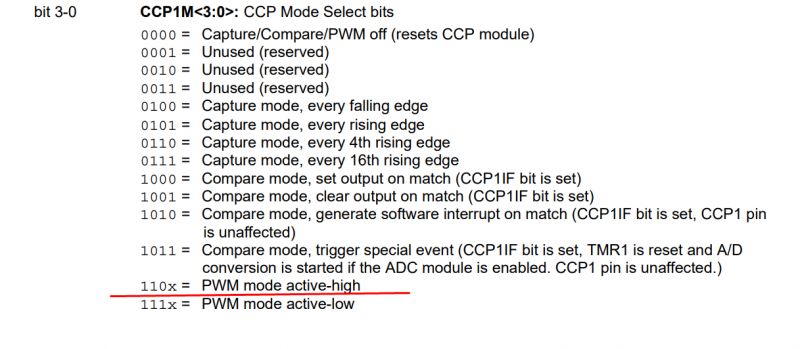
So much for the most important configuration, but we still have CCP1CON. There we will fortunately not count anything anymore:
 .
.
We enter 0b00001100 to enable the PWM in active-high mode (if we want to invert the signal, we can enter 0b1110.
All code:
Code: C / C++
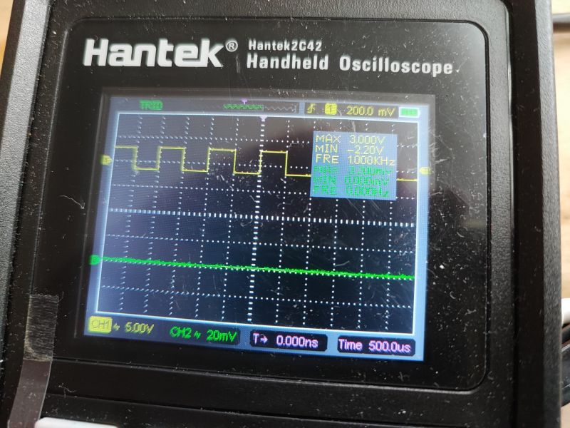
Beautiful 1kHz:
Buttons and fill control .
Now you still need to be able to change the fill of this PWM. As I have already written, this boils down to changing the value of CCPR1L from 0 to PR2+1. For convenience, I have decided to implement this using two buttons.
To activate the button, you need to:
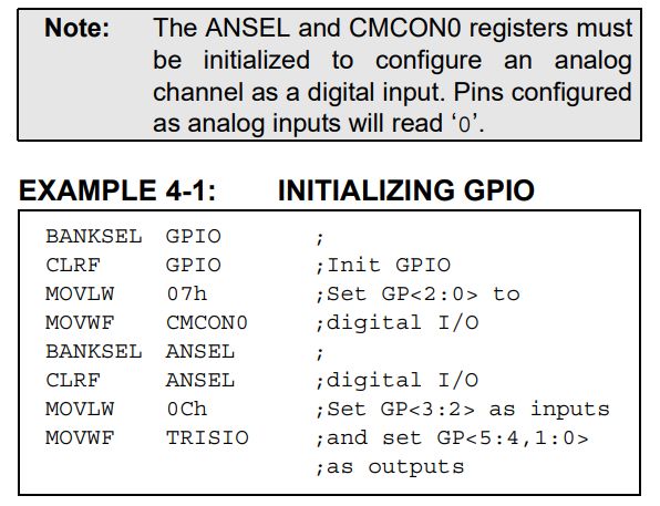
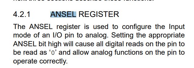
- make sure that the ADC/comparator roles are disabled
- set the corresponding bit of the TRIS register to 1
Information from the datasheet note:
 .
.
If we forget, all digital read operations will return zero!
 .
.
Then you can read the state of the button via e.g. the GP1 bit for GPIO 1. There are no separate ports here!
In addition, care should be taken to establish some state when the button is not shorted - for example, when connecting the button between GPIO and VDD, a pull-down resistor should also be given, so that by default the button has a state of 0. When pressed it will be 1.
Code: C / C++
A little further on, in a loop:
Code: C / C++
I simply increment the duty value by the selected value and make sure it does not exceed PR2+1, then save the result. In addition, I block the execution of the main loop for some time, because otherwise these duties would be increased as fast as the MCU executes the instructions. It is generally better to do this without blocking the whole program, but this is just a simple example anyway....
The whole code:
Code: C / C++
Transistor selection .
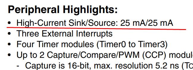
Unfortunately, we cannot connect the LED strip directly to the GPIO of the microcontroller. It's far too low current capability doesn't allow us to do so - we could light one LED from the GPIO (with a current limiting resistor), but there's not enough current for the whole strip. See the datasheet note for details, for example for the PIC18F2550:
 .
.
25mA is not enough, we want from 1A-2A, so some kind of transistor will be useful. Preferably a MOSFET, as such is voltage controlled.
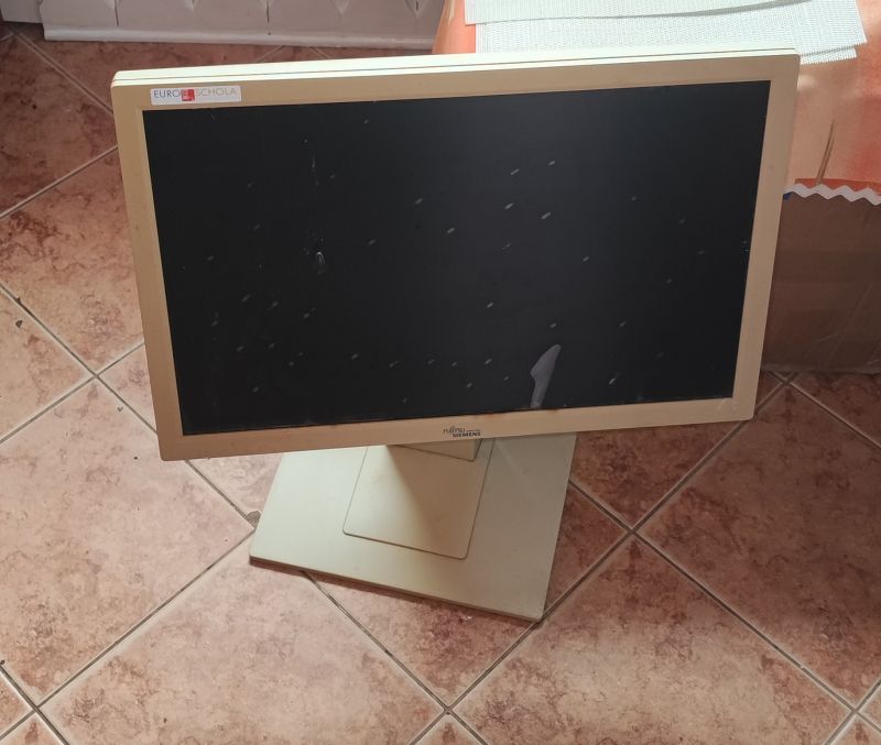
I sometimes scrap equipment for this purpose:
 .
.
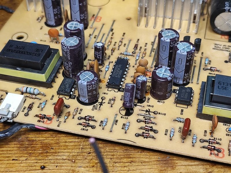
I found two interesting pairs of MOSFETs in the inverter circuit feeding the fluorescent lights of this monitor:
 .
.
They are controlled by an OZ9938DN.
All in DIP housings. A bit of flux and solder on the pins, and the circuits fall off the board by themselves:
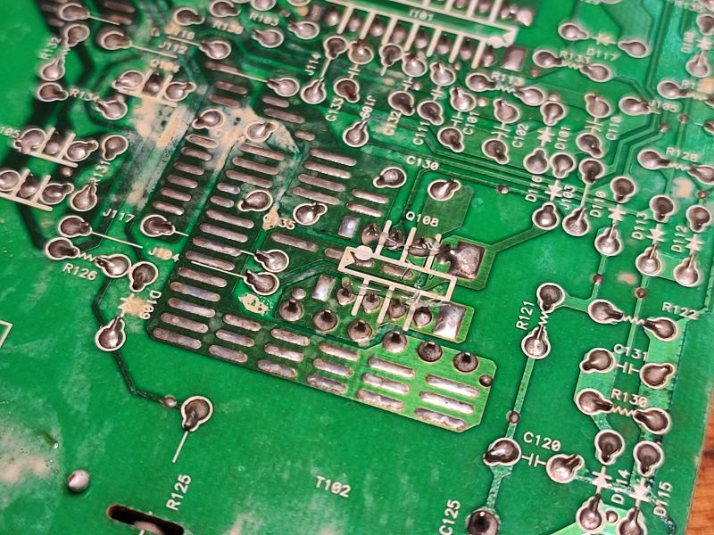
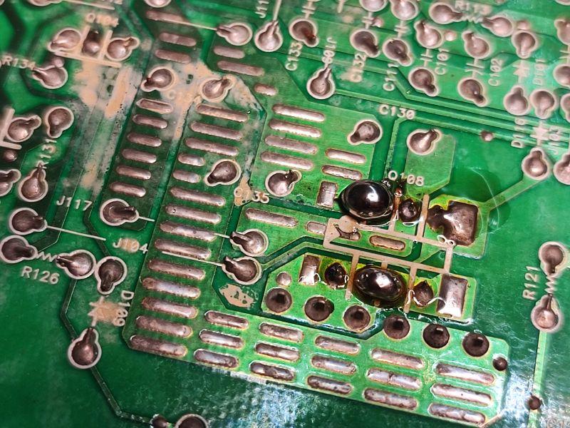
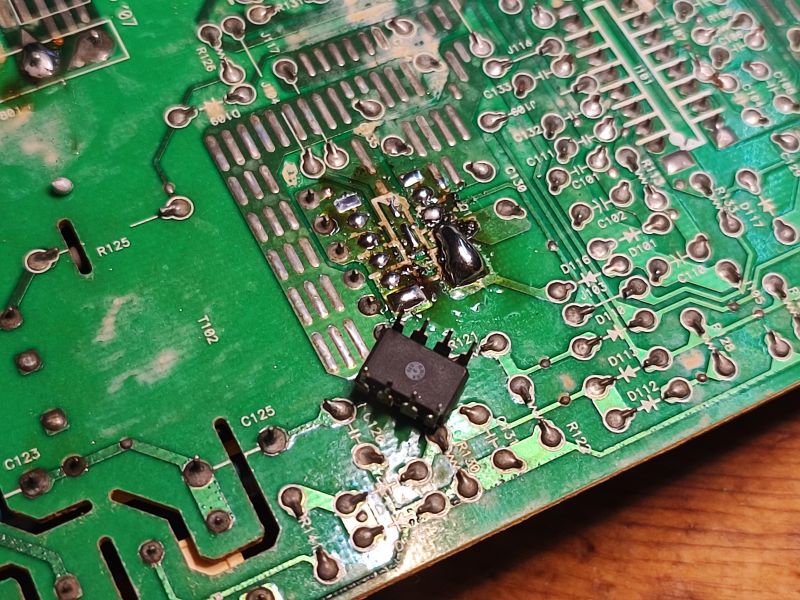
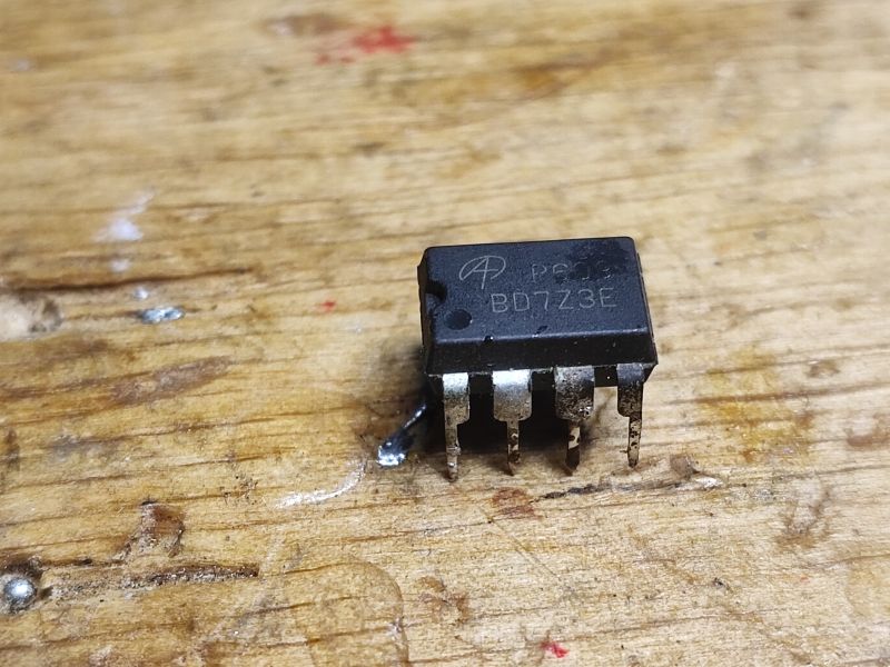 .
.
This is the AOP609 - two MOSFETs in one housing, N and P. Complementary pair:
 .
.
I will only use one of them, the one with the N-type channel. Its parameters look promising, RDS(on) (resistance in conduction state) for Vgs (gate-source voltage) 4.5V is supposed to be less than 75mΩ, but here it is still worth looking at the characteristics:
<span class="notranslate">
 .
.
It looks like this MOSFET will fit - 5V from the PIC will be able to drive it. Not every MOSFET would be suitable for this.
By the way, there are a lot of cool MOSFETs like this on the TV PCB:
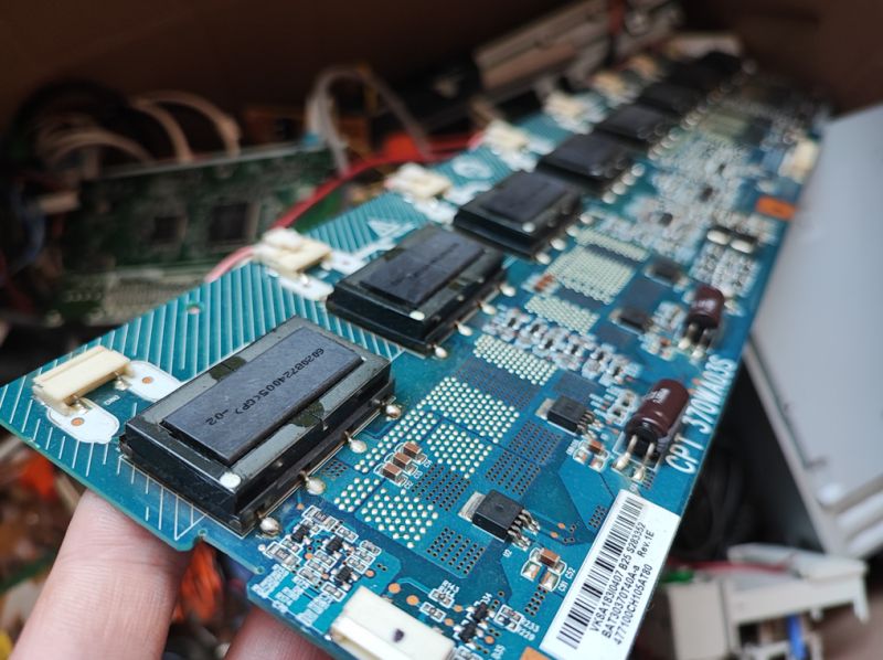 .
.
Here I recovered as many as 8 D606s!
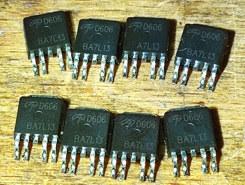
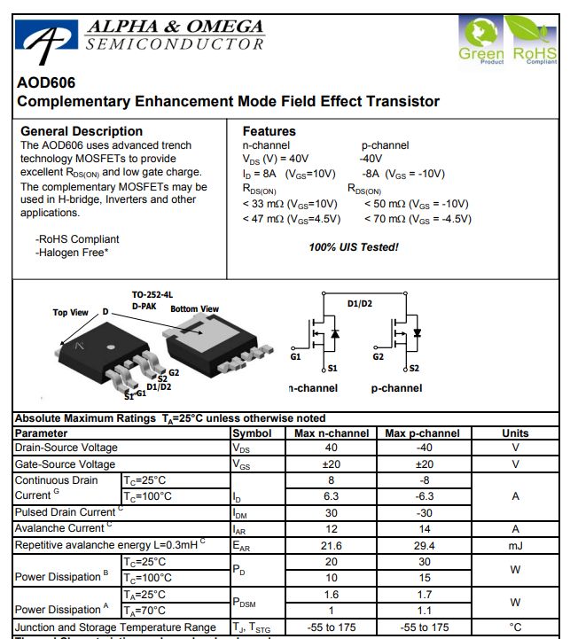
AOD606, again a complementary pair but with slightly better heat dissipation:
 .
.
Test with oscilloscope .
I put everything together to test - I connected the MOSFET source to ground, the gate to the signal output via a 1k resistor, and connected an LED strip between the drain and 12V+. I ran this with a lab power supply, the waveform is shown on an oscilloscope for reference:
You can see very nicely here how the brightness of the bar changes with the signal fill.
Translate to board .
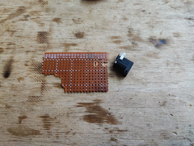
I use a ready-made single-sided drilled board to quickly assemble the prototype. It is comfortable to solder on, but you have to lower the temperature of the soldering tip a bit and use flux, otherwise the pads fall off quickly after overheating.
 .
.
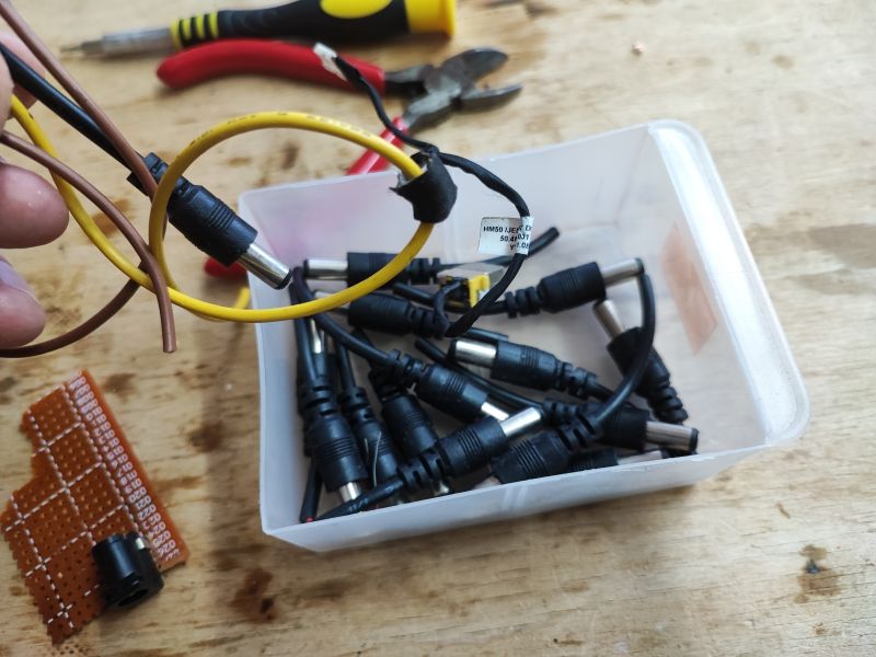
I found a bag of DC jack terminals discarded by some company the other day, one of these will be as good as found:
 .
.
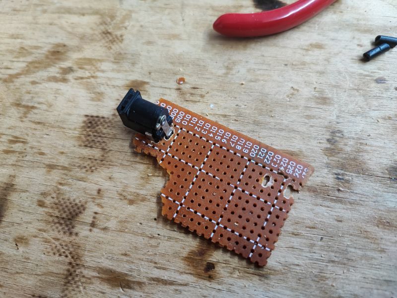
Folding:
 .
.
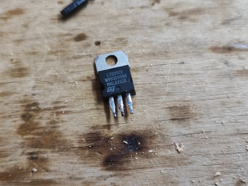
The PIC requires 5V and the strip is powered by 12V, so a 7805 will come in handy, from electrical junk of course:
 .
.
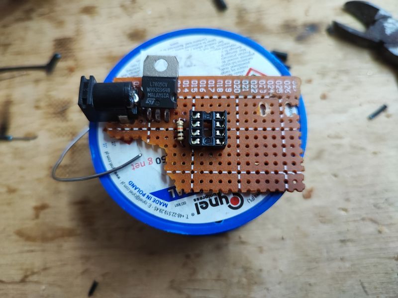
Progress:
 .
.
Test, you can also see the capacitors added (essential for stable operation, literally without that 100nF I could see my MCU resetting):
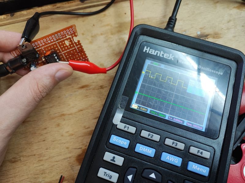 .
.
Almost done, added resistor on MCLR, gate resistor:
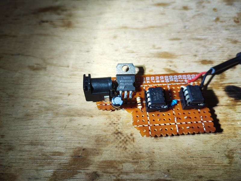 .
.
Added buttons and barely visible SMD pull-down resistors from buttons:
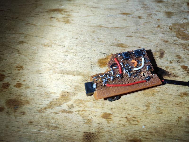
Final test .
The MOSFET used is quite weak compared to other strip controllers, but I only needed to handle 2-3 metres of LEDs taking up to 2A in total. A full-day test showed that at full load the MOSFET is only slightly warm. It looks like it will perform well in its role.
What could be done better? .
Random order:
- 7805 could be replaced by something smaller, but this was on hand
- the PIC clock could be slowed down considerably, this would also save some power
- a more powerful MOSFET could be given
- solder, etc.. - you know
- you could make better use of this PIC because basically it doesn't do much now but I wanted to come up with something as part of a practical tutorial....
Interiors of factory LED controllers .
If you want to see, on the other hand, what the dimmers available on the market look like, I have already described them in several topics. It is also worth checking what MOSFETs are inside - this is covered in the topics:
Miboxer FUT037W+ LED strip controller with TuyaMCU - communication protocol, OpenBeken .
RGB LED strip controller (remote control only) for £5 - BKL1013
WiFi/IR LED strip - WX300P - music mode - hidden buttons [W800-C400] .
A dimmer without MCU is also worth seeing:
Simple analogue LED dimmer with potentiometer - without WiFi - Bowi 002066 12V 8A manual .
Summary .
I hope someone enjoyed this one-day project. Perhaps in the next part I will develop it a bit, just what else can be added to such a simple LED strip controller? Do you have any ideas? Or maybe to do something else at all in the next part, also on this small PIC in a DIP08 case, just what?
PS: Some sort of enclosure would also be useful - but that maybe separately as a 3D print.


Comments
AVE... Things that can be improved: 1. the modules configuration code should be in a separate function, called in the main loop once, it's nicer that way. 2. After configuring the oscillator, add:... [Read more]
In principle, the remarks are right, although I skipped point 3, as I am trying to create simplified mini-projects/tutorials, and the introduction of buttons with debouncing on the timer is basically a... [Read more]
In the main loop? More like once at the beginning but the main function. [Read more]
A very interesting topic. Respect. Small comment. However, slightly different processor stated in the subject header. [Read more]
Correction made. I'll find time then I'll measure the current of the PIC itself and then modify the program to reduce the clocking to save power and try replacing the 7805 with a Zener diode as @urgon... [Read more]
. Why the mushroom? A completely misguided idea. For such a primitive stabiliser to do its job, the same current must always flow into the circuit, equal to the maximum current drawn by the circuit downstream... [Read more]
AVE... @acctr As usual you demonstrate your ignorance. It makes no sense to use a 7805 family stabilizer for a circuit that draws a few mA at most. As the circuit draws several microamperes, the... [Read more]
Your tutorials on PIC microcontrollers are great. Unfortunately, they are not very popular in Poland. I myself have several different PIC16Fs in my drawer and I don't know what to do with them. [Read more]
AVE... Programming? The biggest issue with PICs is the cost of the programmer. I recently bought a new PICKit 5 and spent almost 500PLN on it. A PICKit 3 used to cost me probably 200 or 300PLN. There... [Read more]
A simple Arduino-based programmer can be built. All you need to do is provide 12-13V for the VPP. E.g. using this project. https://makerprojekte.de/en/arduino-pic-programmer/ [Read more]
I'll convert this dimmer of mine to a Zener diode and we'll see, measurements and tests will show if it works. I use it every day so if something goes wrong I'll know quickly. @Urgon , what PICs are... [Read more]
https://www.olx.pl/d/oferta/programator-pickit3-CID99-ID116Fts.html [Read more]
AVE... I have recently been programming the PIC12LF1501. Before that I spent a lot of time with the PIC18F45K50. 16F648A, 10F322, or 16F1827. I also have dsPICs and PICi 32's in the queue. PICKit3 has... [Read more]
I have been using PICKIT3 (and PICKIT2) from Windows 7 to Windows 10 and have never experienced a problem. The only problem I've experienced recently with Pickit2 on Windows 10 - the PICKIT2 software... [Read more]
AVE... The problems in question are related to the situation when the microcontroller is powered from the programmer, it is also possible that it is the hardware version of the programmer itself... The... [Read more]
The electronicist is based on facts, i.e. real properties of electronic components, not imaginary properties, which are just your invention here. The 78xx stabilisers require no such thing as a minimum... [Read more]
Today I was playing around further with the PIC12F683 and needed to run another GPIO, namely: - GP4/OSC2/CLKOUT - GP5/OSC1/CLKIN Both in output mode. In the default configuration, however, they don't... [Read more]