F&Home - Polish building automation system, first step-by-step commissioning
(Sponsored)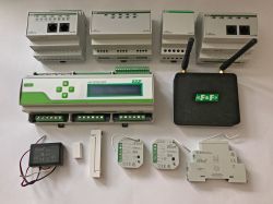 .
.
F&Home is a fully customisable, Polish home automation system offering unified integration of wired and wireless solutions. Automation in F&Home is created using a comprehensive, visual system based on Node-Red and control from phones is via the Fox app, also compatible with Wi-Fi-based solutions.
In this topic, I will show this system in practice. This will essentially be the first part of an adventure with a smart home solution from F&F and in this topic I will present:
- some of F&Home's wired and wireless devices
- the interiors of a few selected devices
- the configuration of the main mH-Developer server
- connection of a LAN-Radio gateway to the server
- first start-up of wired (mH-Developer expansion modules) and wireless devices
- a first look at the Fox application
In the second topic in the series, I will build on the results from this topic and only then focus on the free creation of logic in the new Node-Red-based Configurator.
The new release of F&Home is fully compatible with older hardware, so if you already own some hardware from the discontinued series, there's nothing stopping you from using them with the solutions I show here.
We're about to get started, just a little more....
Organisational notes .
Here are a few words worth writing, but they do not directly relate to the system itself:
- some of the equipment from the system operates on deadly mains voltage, all care must be taken when assembling, operate with the power off, etc....
- due to the length of the topic, I am not repeating here all the information from the documentation about each device, so I strongly recommend you also read the official, Polish-language and detailed documentation from F&F .
Single wired and wireless automation system .
Wireless part of the F&Home system is based on a central unit and expansion modules. Additional systems can be connected to the unit via various buses, such as (depending on the server) CAN, ModBus, LAN. Expansion modules can be added gradually as the system grows, allowing the system to be adapted to each household.
 .
.
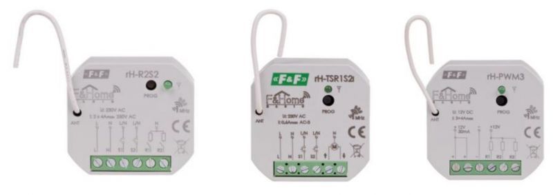
The Wireless part of the system is based on proprietary F&F technology based on proprietary radio receivers/transmitters operating in the 868MHz band. This solution uses dual radios mounted in the servers and very effective radios described as LR, or Long Range (long range, up to 350 metres).
 .
.
 .
.
 .
.
The heart of the F&Home system is the central unit, supported units include the rH-SERWER-DIN2, DESKTOP2 and DEVELOPER models. This presentation will be based on the mH-DEVELOPER.
Review of the equipment used for the presentation .
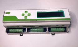
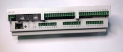
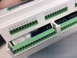
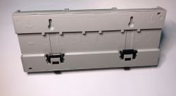
Server mH-DEVELOPER is the central unit of the F&Home system, contrary to appearances, it does not only support wired system, but is also able to support wireless modules when the appropriate gateway is connected to it. The mH-Developer is mounted on a DIN rail and controls heating, lighting and electrical sockets.
 .
.
 .
.
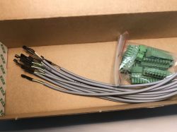
We also get DS18B20 temperature sensors in the kit:
 .
.
mH-BLR LAN-Radio is a gateway that allows you to connect radio devices to F&Home. It comes with two long-range antennas and a power supply. The LAN-Radio communicates with the mH-DEVELOPER wired over Ethernet.
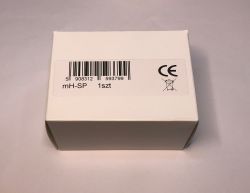
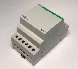
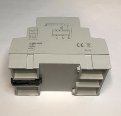
Interference filter mH-SP is needed to connect the mH-Developer. It protects system components from mains interference and surges.
 .
.
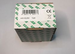
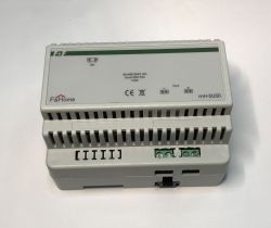
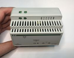
Power supply mH-SU50 is connected between the mH-SP filter and the mH-Developer CPU. It provides the 24V necessary for the operation of the server.
 .
.
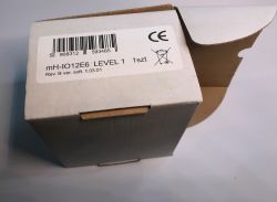
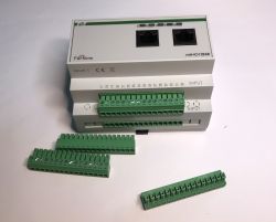
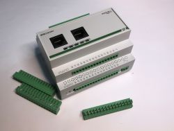
Module mH-IO12E6 is an extension for mH-Developer. It is connected via the CAN interface. The module occupies 6 fields in the switchgear. It is supplied with 24 V. Shown here is a level one module (LEVEL 1), levels allow several modules to be connected with the same role. The mH-IO12E6 is used to control lighting (or other consumers operating on the on/off principle) as well as motorised receivers (suitable for controlling external blinds as well as vertical and horizontal shutters).
 .
.
The module manages the switching of lights or motors via relay actuators of the mH-R8x8, mH-R8/2, mH-RE4 or mH-R2x16 type.
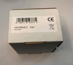
Module mH-R8x8 is an executive (relay) module connected to e.g. mH-IO12E6:
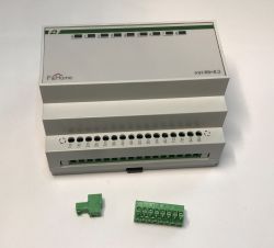
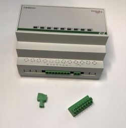 .
.
Module . mH-V8 is an eight-channel executive module. It controls the operation of solenoid valves connected to the module outputs. It is adapted for cooperation with mH-S8 temperature sensor modules.
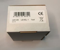
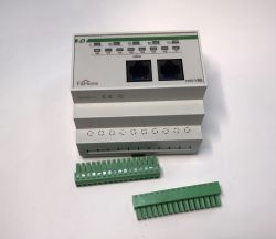 .
.
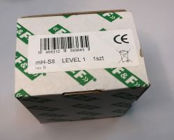
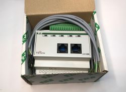
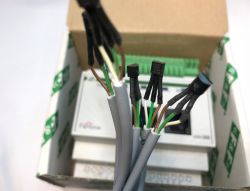
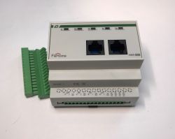
Module mH-S8 is an eight-channel controller that works with digital temperature sensors that measure temperatures from +5 to +40 degrees, with an accuracy of 0.1 degrees. It is adapted to operate with mH-V8 executive modules controlling solenoid valves in the heating circuit.
 .
.
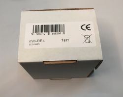
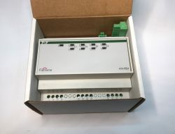
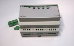
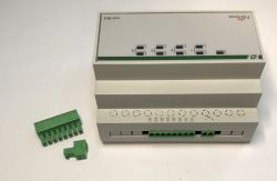
Module mH-RE4 is a roller shutter relay module. It offers protection against j simultaneous activation of the up and down direction and against immediate change of direction (time-out). It has a spark extinguishing circuit, extending the life of the relay contacts and eliminating interference on the network.
LEDs on the front of the unit to show the current status.
 .
.
Now it's time for some wireless modules - they also work well with the whole system and can be conveniently integrated into the wired part of the system too. Today's wireless modules are connected to the system.
The already mentioned LAN-Radio gateway is used to connect them.
The rH-R1S1 LR module is a combination of a relay and a contact input. The module sends information about short-circuit and open contacts to the system and controls the relay, which can switch on any electrical circuit, for example, it can switch on a light. rH-R1S1 is powered from the mains.
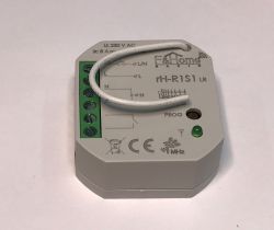
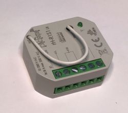 .
.
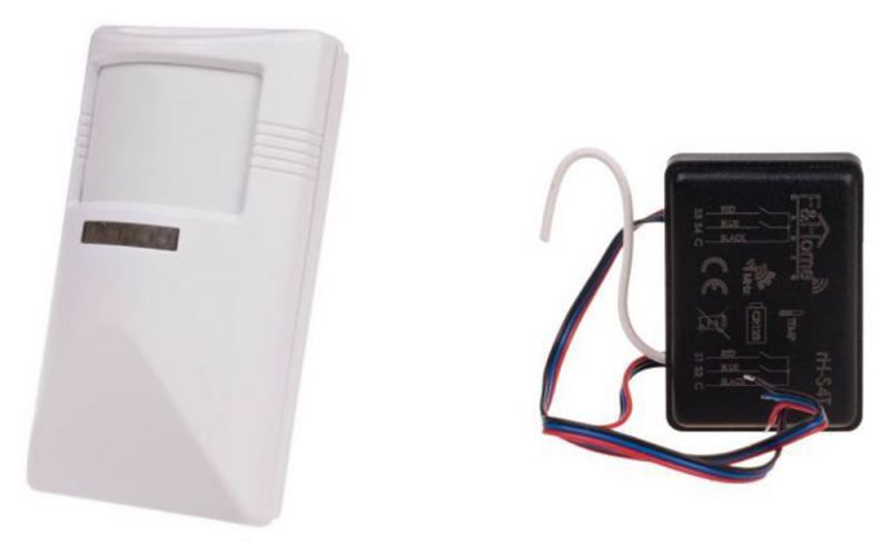
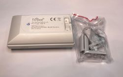
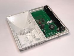
Battery-powered rH-P1T1 LR is a motion sensor with temperature probe. It is powered by two AAA batteries. It can trigger any automation created in the Node-Red-based configurator.
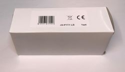
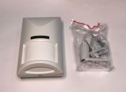
 .
.
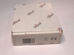
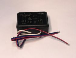
Cushion rH-S4T is a battery-operated four-channel transmitter with temperature measurement. It allows the connection of a quadruple monostable button. It is powered by a CR123 (lithium) or SL861/S battery.
 .
.
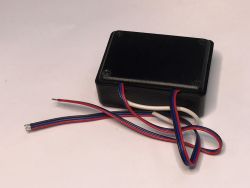
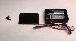
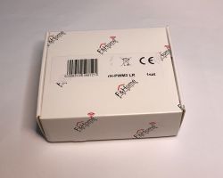
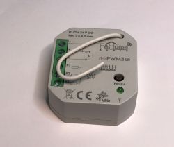
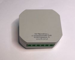
Module rH-PWM3 LR is a low-voltage three-channel PWM controller capable of controlling any type of device, but primarily used for LED lighting.
 .
.  .
.
Small rH-WMC is a battery-powered door/window sensor. It is based on a reed switch. It can trigger different types of scenarios, including, for example, automatically turning on a light:
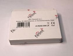
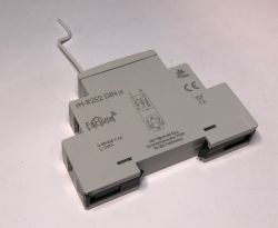
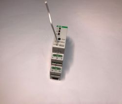
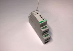
In the F&F offer there are also wireless DIN rail mounted modules - for example rH-R2S2 DIN LR . Two-channel relay with two-channel transmitter. Two pushbuttons and two receivers can be connected there. The relays are voltage-free here too, so you can switch on equipment supplied with any voltage.
 .
.
Interiors of selected devices .
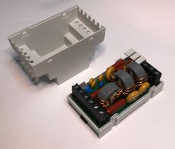
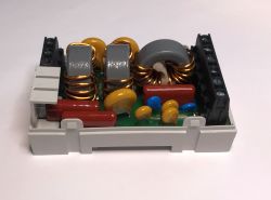
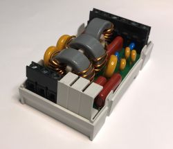
Here are photos from the inside, for selected devices only. To start with, something that is already indicative of the class of the whole system - the mH-SP filter. I have complained many times on the forum that budget solutions don't take care of this at all, and now I finally have the opportunity to show how it should be implemented:
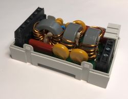
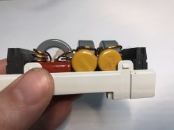
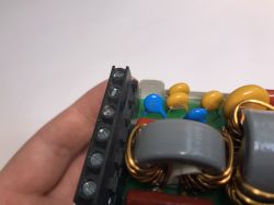
 57e9bbd47 .
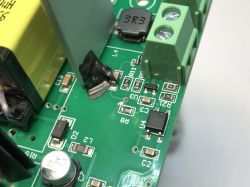
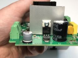
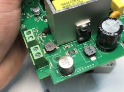
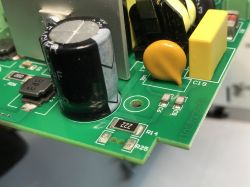
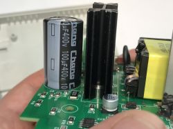
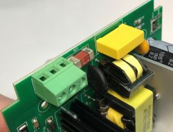
I also checked the construction of the mH-SU50 power supply, which, as you can see, nevertheless has its own filters, and even a varistor was found. The manufacturer has not regretted anything. The power supply is built in flyback topology based on the CR6853.
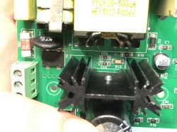

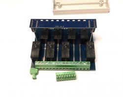
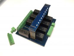
I also had a look inside the executive mH-R8x8.2 relay module, from which you can see that the manufacturer has even strengthened the high-current paths with a bonding agent so that they can cope even under extreme conditions:
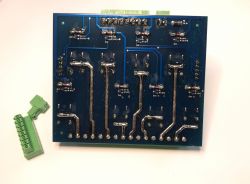
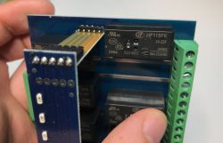
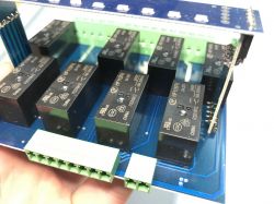

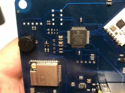
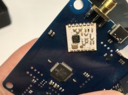
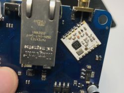
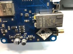
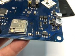
You will also probably be interested in the inside of the LAN Radio gateway, which is built around a PIC24FJ256GB206, ESP32 and up to two radio modules, ensuring that F&Home has good range even in difficult conditions.

 .
.
mhDeveloper - first run .
We start by connecting the mH-SP filter module and the 24V DC power supply mH-SU50. We connect the power supply to the mhDeveloper unit, making sure that the polarity is correct.
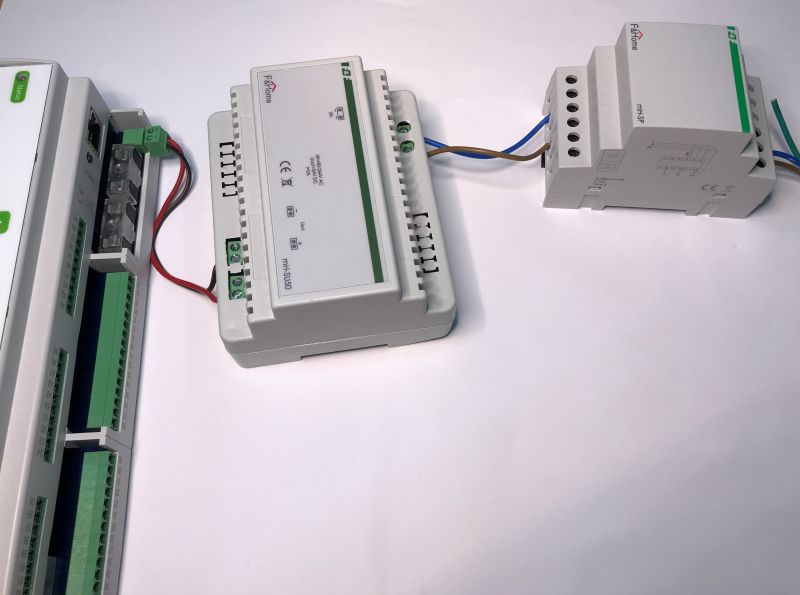 .
.
Only then do we connect the power. mhDeveloper should boot automatically. Booting will take a few seconds and then the firmware version will be displayed:
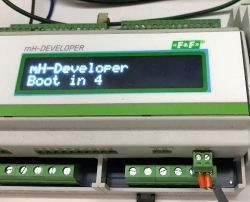
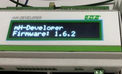 .
.
At the moment I am not connecting the Ethernet yet, because I want to show that it will work even without it.
mhDeveloper - lighting control .
mhDeveloper has built-in, ready-made mechanisms designed to control basic automation in the smart home. We will start the adventure by activating buttons. Inputs 1-12, polarised by the COM A connector, are used for this purpose. COM A is the common level for inputs 1-12. If the inputs are to be controlled by a high level, the power supply ground must be connected to the COM A connector. If the "Input x" inputs are to be controlled with a low level (e.g. via OC outputs), the COM A connector should be connected to the plus of the power supply.
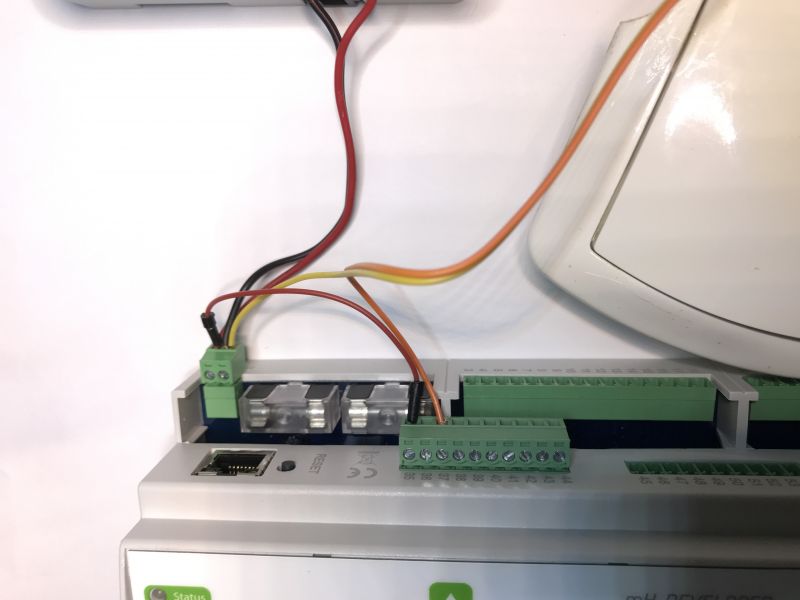 .
.
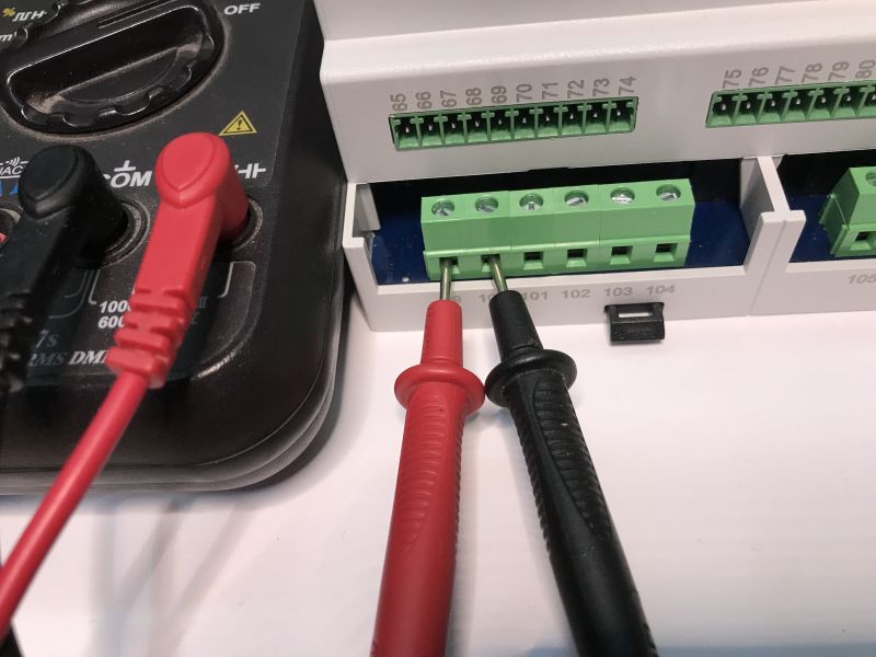
These inputs are waiting for a bell button and pressing it once flips the status of the corresponding relay (relays 1-12). The relays there are connected in voltage-free mode, so they can control both 230V and 24V circuits or whatever.
To start with, I checked them with a multimeter:
 .
.
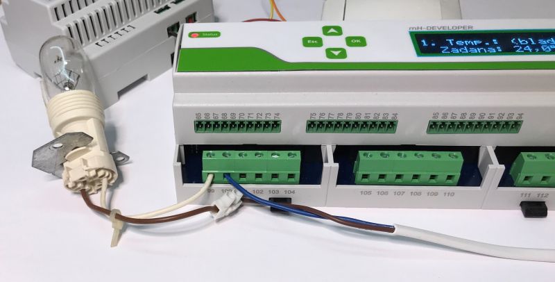
The control works - this is how the lighting control can be activated. I connected a 230V supply and a light bulb to the appropriate relay so that it breaks the circuit:
 .
.
mhDeveloper - heating control .
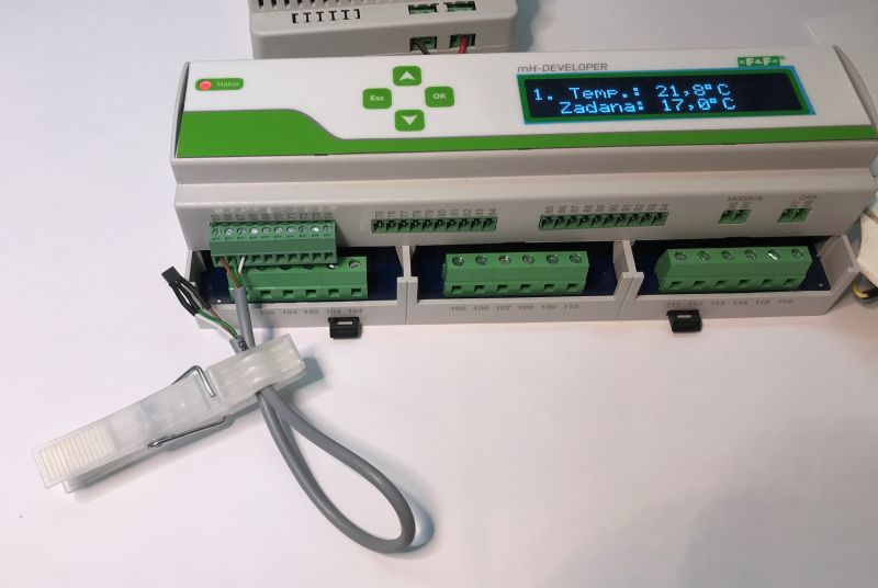
Similarly, here we have 9 temperature sensor inputs and 8 actuator outputs (for valves - triacs). The ninth temperature sensor has no associated triac and can be used as an additional, informative reading.
 .
.
Temperature readings are available on the display, as well as in the configurator and in the Fox app (when paired).
Here is a short demonstration showing how quickly the readings are refreshed:
Next, we can run the heating control. This is fully configurable and can also be used for cooling, but in the default configuration it works so that the output turns on when the temperature reading is below the set temperature. The set temperature can even be changed from the LCD (buttons).
For demonstration purposes, I used a light bulb instead of a heating system. The bulb switches on when the temperature is too low and its short distance from the sensor makes the sensor warm up. When the sensor heats up, the desired temperature is reached and the bulb goes off, so the sensor cools down. The cycle loops.
In the following section we will see how this system can be configured.
Access to the mhDeveloper via LAN .
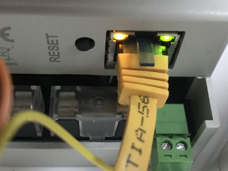
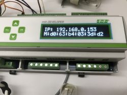
mhDeveloper also allows more advanced mechanisms to be created. This is accessed via the local network. You get to it via the IP displayed on the screen, or you can find it in the DHCP client list. Importantly, this does not require pairing with the cloud - the cloud is not mandatory, so there are no privacy concerns.
LEDs above the connector indicate connectivity:
 .
.
Care should be taken to ensure that the device has a static IP. You can make an IP address reservation for the device's MAC in the DHCP settings.
You then need to log in to the device.
The default login credentials are "admin admin".
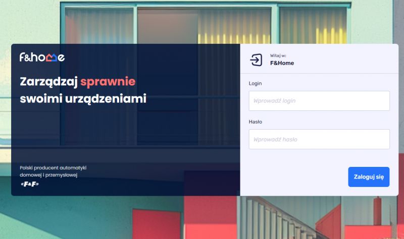 .
.
Once logged in, we have access to the configurator, devices, wireless gateways and other settings.
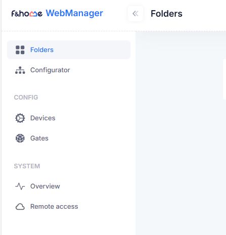 .
.
The configurator allows us to create virtually any logic through the Node-Red-based system, this will be detailed in the second part:
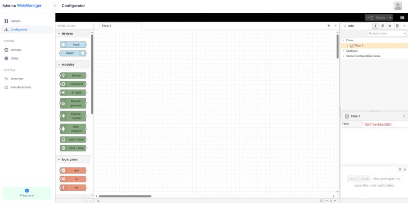 .
.
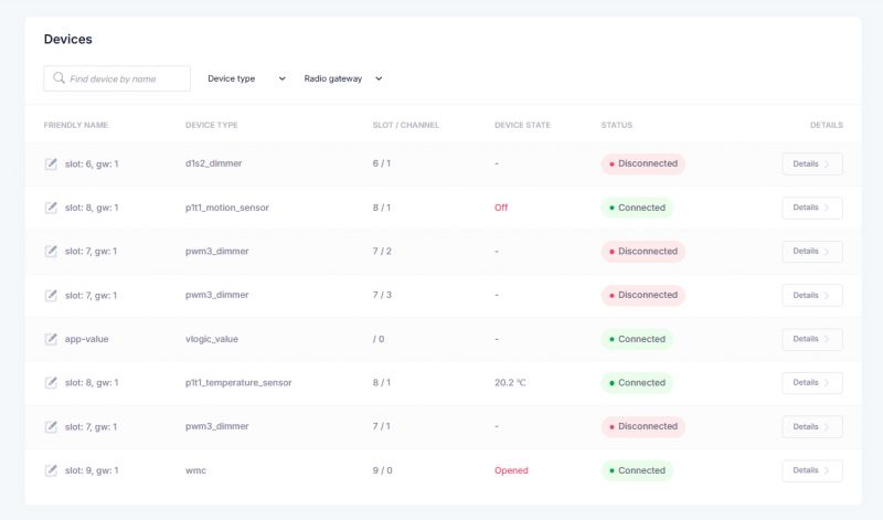
In Devices we have the connected devices, here an example screenshot shows the view already after pairing with the LAN-Radio gateway and adding the D1S2 module wirelessly:
 .
.
The Gates tab, similarly, shows the connected gateways - you can have several of them, further extending the network coverage.
 .
.
The Overview tab shows us the current status of the main server - CPU, memory, data, network and so on:
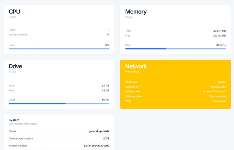 .
.
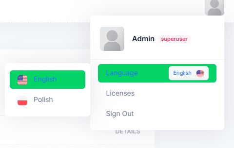
It is also worth remembering that Polish is available in the system - whatever you prefer:
 .
.
Fox application - first connection to mhDeveloper .
The mhDeveloper can be used without the app, but the possibilities it offers are tempting, to say the least. Here we explore it in more detail.
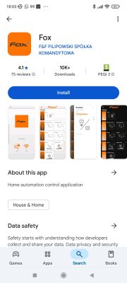
The Fox mobile app allows convenient operation and configuration of wired and wireless F&Home systems. The Android app is downloaded from Google Play:
 .
.
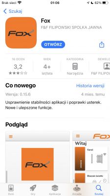
On iOS, on the other hand, it can be downloaded from the Appstore:
 .
.
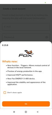
To begin with, it is a good idea to create an account.
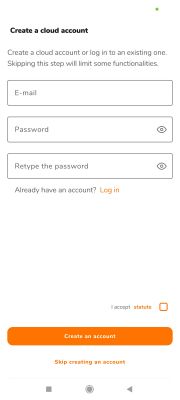
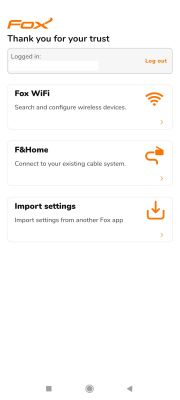 .
.
Connecting mhDeveloper to the new Fox app is very simple. All you need to do is connect your phone to the same local network that your server is on. The app should search for the device itself.
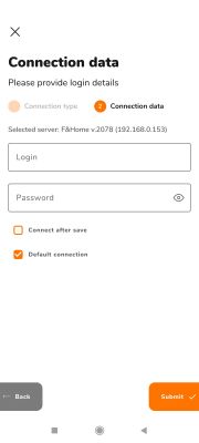
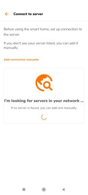 .
.
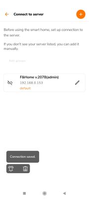
If it doesn't search for it, it's worth taking a look at the mhDeveloper panel to see what IP it has been assigned. You can also add it manually - via the IP address.
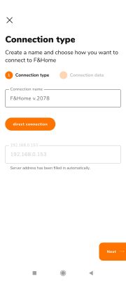 .
.
The default details are: "admin admin"
Fox - scenes and programs .
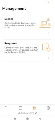
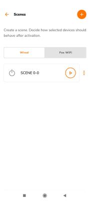
In the Fox application, advanced scenes and programmes can be created. The Management tab is used for this. In it we have separate options - Scenes and Programs:
 .
.
The Scenes tab allows you to create both wired and wireless scenes:
 .
.
In editing a scene, you can change its name and icon. At the same point, we again click on the plus sign to add devices. For each one you can define the operation and the time.
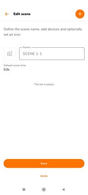
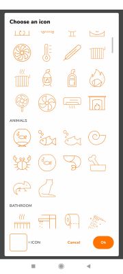
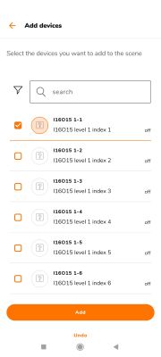
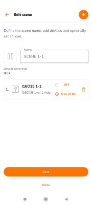
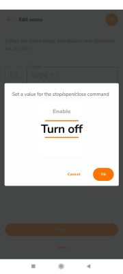

Based on this, I created two example scenes - the first turns the lights on, the second turns them off. This would be, for example, turning the lights on or off in an entire flat or section of a building.
A short presentation:
Additional IO for mhDeveloper - mH-IO12E6B .
mH-IO12E6B is a newer version of mH-IO12E6 . Connection is very simple - you need 24V power and CAN from one of the modules or directly from the main server.
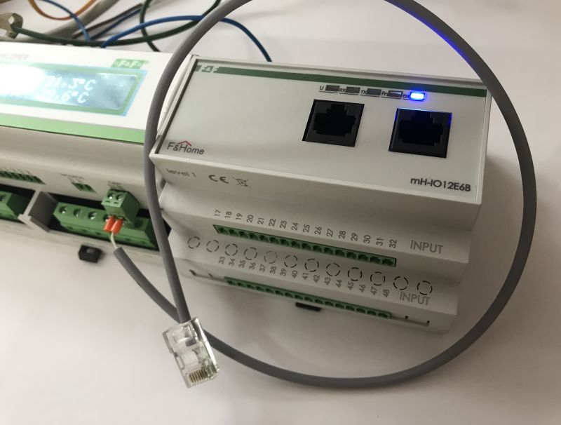 .
.
After the operation, power is restored - from this point on, the new outputs will be visible in the application, those from the mH-IO12E6B module.
As a test, I pulled up one of these outputs to the power supply using a 10k resistor and tested its behaviour with a multimeter:
The output puts out a voltage accordingly, now the mH-R8x8 can be connected to it. The mH-R8x8 can then be used, for example, to switch on 230V lighting:
Additional sensors for mhDeveloper - mh-S8B .
It is time to connect another module. The main server has one connector, but that's not a problem - we simply connect one module to the other, in series:
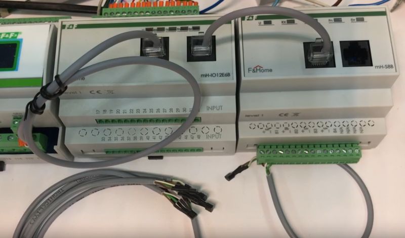 .
.
Once power is restored, the new sensors should be immediately visible in the panel. A short test with a powerful torch shows us that the sensor is working:
Additional heating systems (and more) - mH-V8B with mH-S8B
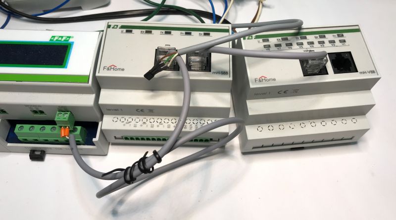
The mH-S8B can be easily connected to the corresponding mH-V8B module, just make sure that both modules are of the same level (LEVEL). The photo shows the method of connection:
 .
.
From now on, temperature sensors connected to the mH-S8B can trigger the outputs of the mH-V8B, all depending on the configuration. Here is an example of a heating setting for a given time, which is then switched off when the appropriate temperature is reached. There is an incandescent light bulb as the heater - for demonstration only.
LAN-Radio Gateway .
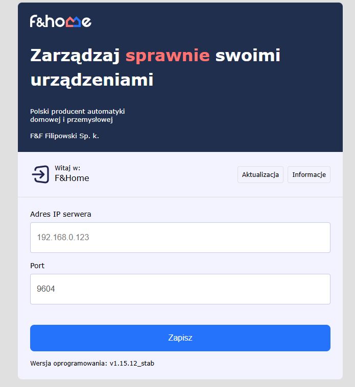
The LAN-Radio gateway allows the uniform connection of F&F radio devices to the main mH-Developer server. The gateway connects to the server by cable via Ethernet. The first time you launch it, you go to its website and enter the IP of the server.
 .
.
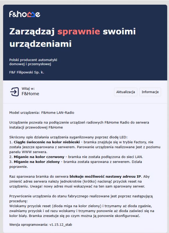
NOTE - if the text fields are not active (cannot be edited), then you need to reset as instructed
 .
.
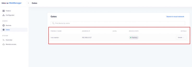
Since then it should appear in mH-Developer in Config->Gates:
 .
.
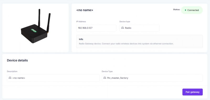
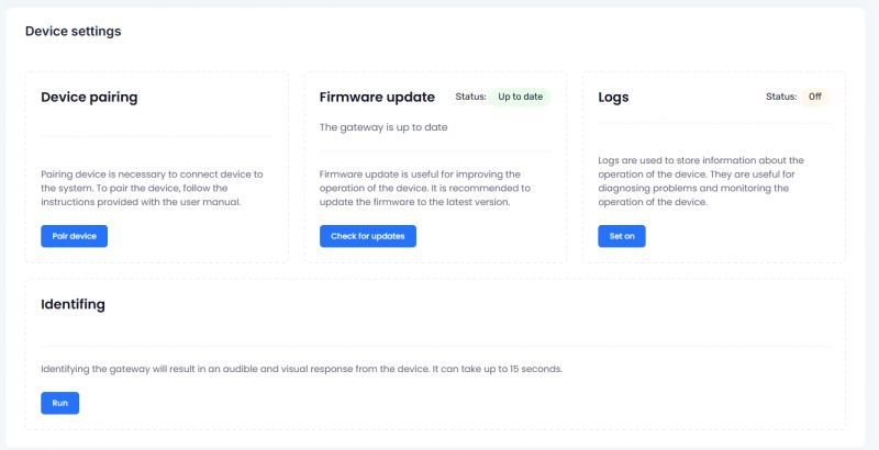
In the gateway settings you can run pairing with the device, update its software, view its logs (if enabled) and it can also be identified (the gateway then emits an audiovisual signal, this is useful if you have several gateways).
 .
.
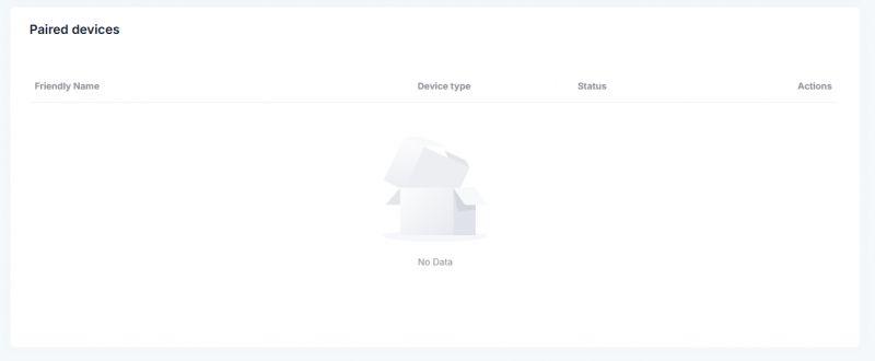
A list of paired devices is also available there:
 .
.
First wireless device .
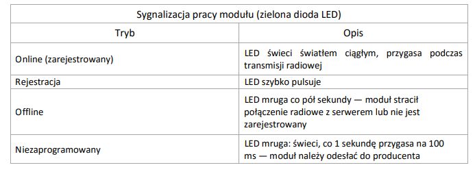
It's time to pair some sort of device with the gateway. For the demonstration, I chose the rH-D1S2-LR dimmer module and plugged it in. The LED started blinking every half second. The meaning of this signal can be found in the documentation:
 .
.
Registering with the system is very simple.
- start pairing in the gateway view
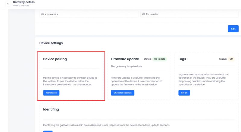 .
.
- system waits for the device
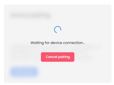 we press the button on the housing.
- press the button on the housing
- after 5 seconds the module will register itself in the system or the program will report an error in case of failure, in case of success the device will appear in the list:
 .
.
From now on, it is also possible to enter the settings of this device and configure it or test remote control:
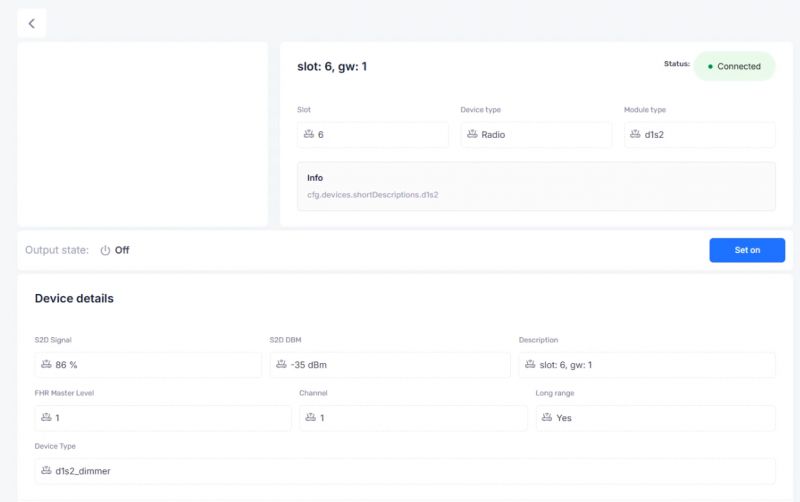 .
.
NOTE: For best coverage, arrange the module's antenna parallel to one of the server's antennas and keep it as far away from the other cables as possible!
Dimmer rH-D1S2-LR .
The dimmer can even operate without pairing, in the so-called stand-alone mode. This mode is also switched on in the event of connection problems. It is then controlled directly via a button, without an app.
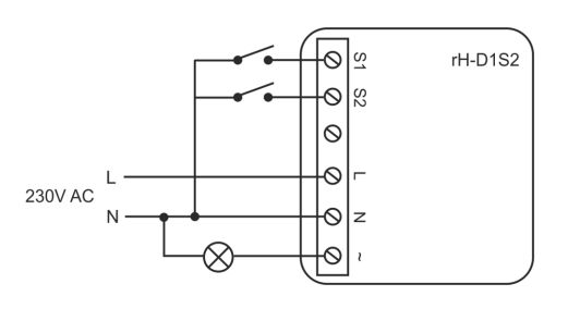 .
.
The operation of the standalone mode is very simple:
- a short press of the button turns the light on or off
- a longer press makes the brightness level increase and stops
stops when you release the button
I paired the dimmer according to the instructions in the previous paragraph. It immediately appeared in the WebManager, as well as in the Fox application. For the test, I decided to start there. There we have control over the brightness level and the on/off status:
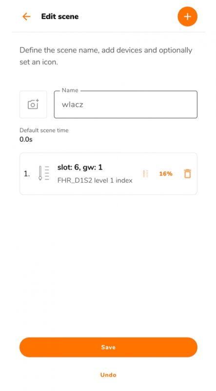
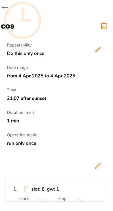
What's more, I can already see that the dimmer has immediately become available for scenes and programmes on Fox:
 .
.
 .
.
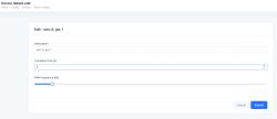
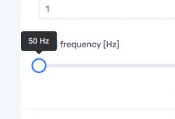
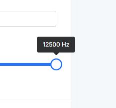
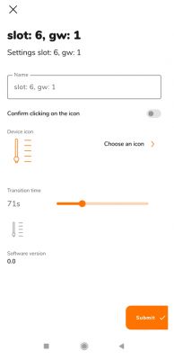
Settings for this dimmer are available in both Fox and Web Manager. In Web Manager you can change the transition time and PWM frequency, in Fox only the time itself:
 .
.
 .
.
 .
.
 .
.
Low-voltage smart controller rH-PWM3 .
Here is another controller, most commonly used to control LED lighting, but equally capable of operating electromagnetic locks or other low-voltage actuators.
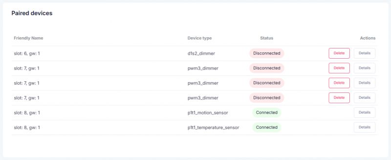
The pairing of the rH-PWM3 is done as I showed earlier, but note - the dimmer will appear in the gateway devices three times - this is not an error, these are separate entries for each channel.
 .
.
Separate dimmer channels will also immediately appear in the Fox app:
Motion sensor rH-P1T1 LR .
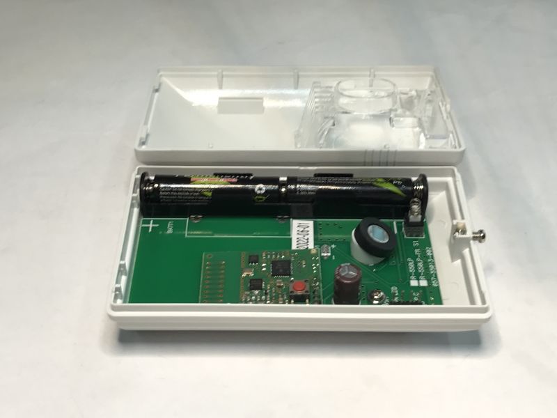
We will now run the motion sensor rH-P1T1 . As the name suggests, it also measures temperature in addition. It starts by inserting two AAA batteries.
 .
.
Then we press the button on the radio module, not to be confused with the button to check that the casing is on. We start the pairing. The gateway should detect the new entities:
 .
.
From now on they are available for use in the system. They can be previewed at Fox - the video shows how quickly and effectively the sensor reacts to actions.
Door opening sensor rH-WMC .
In this case you will need a single AAA battery:
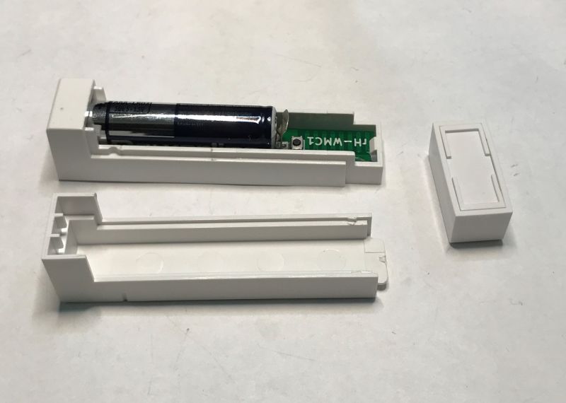 .
.
Press the button from the inside (the one on the outside is only for the sensor to check that it is fitted):
 .
.
From then on, it is available for integration and its response time is really small:
Double rH-R2S2 DIN LR relay .
As before - connect and pair, and in fact even without pairing it will work, as there is a standalone mode here too. Two buttons and two receivers. The control from the Fox also works correctly:
Four switch with temperature measurement - rH-S4T .
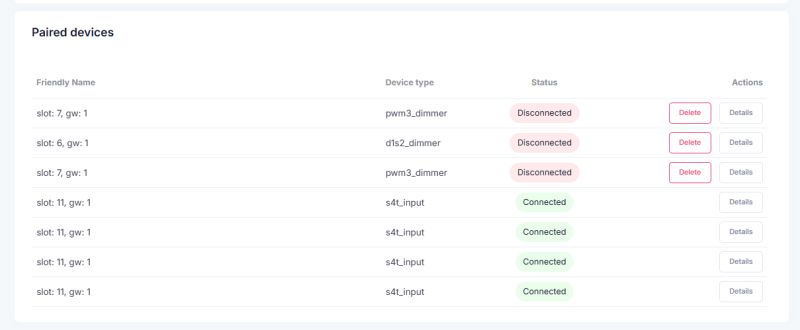
We make sure there is a battery inside (unscrew the screws), check that the battery is not separated by a foil strip to prevent it from discharging in storage, and then short-circuit the S1 and C wires. The gateway should detect the new device:
 .
.
 .
.
From now on, it is also visible in the Fox app:
The response to the buttons is instantaneous, and it is important to remember that we have communication through at least three nodes here. The module sends radio information to the gateway, the gateway over Ethernet to the system's control panel, and the control panel to the mobile app....
Power consumption measurements .
One of the hidden costs of a smart home is the power consumption of all the actuators and the server. This value obviously varies depending on what is running, for example a switched on relay draws more than an open one, but the most important value for me is the base value. How much power does mH-Developer 'cost us' when nothing is switched on?
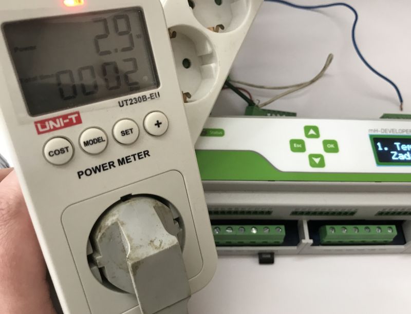 .
.
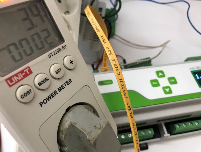
This surprised me. About 3W. I thought I had done something wrong - maybe the server had gone to sleep? I plugged in the Ethernet and started switching things around on the site:
 .
.
3.5W. This is a very good result. Many times on the forum I have tested individual actuator blocks with Wi-Fi or Zigbee communication and such an example switch on Wi-Fi was able to draw these 0.5W without a relay engaged. Here we have 3.5W.... but this together with the main server (because a separate one would be HA for Wi-Fi switches?) and all the logic for lights, heating, sensors. Size-wise, it's similar - I wouldn't be able to pack so much functionality and Home Assistant on a DIN rail....
Range tests .
Out of curiosity I also did some range tests. It's known that a lot depends on the specific conditions in a given location, walls, obstacles, etc, but I thought it might interest someone anyway.
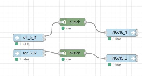
So, I placed the gateway in a room next to a staircase on the third floor of a block of flats. I picked up a rH-S4T kit which I had previously 'programmed' to control two relays from mH-Developer:
 .
.
I will explain the blocks in the second part as I wrote. I pressed the first button halfway down and the second at the very bottom, i.e. by the letterbox. Both relays switched. .
I then took it a step further.... literally and figuratively. From the level below (basement under the gate) it was also possible to switch the relay, it was only from the opposite basement that there was trouble, probably through the thick load-bearing walls.
Footage .
We have also prepared a Youtube video for you covering the content from this topic:
Summary .
This was the first part of a presentation of a Polish home automation system from F&F. Here I presented a selection of F&Home compatible devices, both wired and wireless. Getting the whole thing up and running, configuration and pairing (for the gateway and RF devices) went smoothly. Also, I was able to additionally connect the Fox app, which provides external access to the system (from across the internet) and allows you to run your own scenarios and actions developed in the configurator.
The Node-Red-based configurator itself is so interesting that I decided to leave it for a separate topic. I will only introduce it in more detail in a little while, but I can already say that I have pre-tested it and am very happy with it - it allows you to freely combine and programme the devices I have presented here.
At this point I have the following observations:
- the F&Home system is fully unified and configurable, you can freely combine wired and wireless devices, as well as battery-powered and high or low voltage devices
- the F&Home system offers optional integration with the F&F cloud and the Fox app, but this is not required for operation - if someone does not want to connect to the cloud, the system will work fine locally
- devices from F&Home, while allowing for free configuration and automation, also have built-in action mechanisms to get the system up and running quickly. In mH-Developer, for example, the heating works even if you don't connect an Ethernet cable at all, and radio devices without pairing work alone in autonomous mode
- Similarly, if you do not yet have a gateway and a central unit, but already want to connect F&F modules to the boxes, there is no problem with this - the autonomous mode will manage and the house will be functional even without a server. Very convenient
- reaction to events recorded by the wireless sensors is immediate, I was not able to feel the delay when testing with the door sensor or there with the motion sensor. In addition, tests showed that the radio buttons controlled the relay even from several floors away in a block of flats where my Wi-Fi doesn't reach for a long time....
- F&F radio devices, in addition to their eponymous functionality, often offer a temperature reading, which I think is a cool and useful addition. In open source solutions myself, this sensor is often added, and in F&F I see that this too is ready
- the workmanship of F&F devices is really solid and does not resemble budget no-name products that are sometimes presented on the forum, for example this server power supply not only has proper EMI filters itself, but a separate filter module is available in the kit
- the F&F system is scalable and can cope even in large buildings, both in wired (RS485, CAN) and wireless (gateways) versions. The gateways are connected to mh-Developer via Ethernet, and you can have several gateways, the system even comes with a tool to determine which gateway is which (audiovisual signal)
- the mH-Developer main server itself, which is being tested here, is designed in such a way that it can basically be enough for you to start with - later on, you can buy additional modules. Lighting, heating as well as other systems can be adequately handled by it.
That's it for today - to be continued in part two. Have you used F&F systems, what are your experiences? .
[Advertising cooperation with F&F Filipowski sp.k.].


Comments
There used to be something like "Sterbox" by another Polish company. It looks similar, except that it has much greater capabilities and a much better application and dedicated radio modules. The only... [Read more]
What is the cost of such a kit? [Read more]
Do the battery devices have battery voltage monitoring and a central reminder to replace the battery? [Read more]
Perhaps a minor question, but I will ask it nevertheless. Has a Polish company provided for the Polish language in its product? [Read more]
. [Read more]
. Here I believe is the more important element. No obligation to connect to the cloud means that in the event of an internet failure we still have a fully functional system - is this true ? Somehow... [Read more]
There you go, I've checked it out for you, although I warn you that the video is in very amateur conditions, so perhaps a textual answer first: - the automations (those that are done in the Configurator... [Read more]
Phew, I got through to the end, but it was worth it, because I haven't read such a factual and practical description on Elektroda or anywhere else for a long time. A big plus from me. I would have... [Read more]
I have been aware of this problem of naming for a long time, simply as a content creator, but over time I have come to the conclusion that, since this type of naming is being pushed through the trade and... [Read more]
. This is very good news. So is the 'cloud' just a corporate VPN for external communication and nothing more? This is important because if this is the case, having your own VPN server enables you... [Read more]
. I have been using automation for a good 10 years. I have over 180 components. To this day I still have support and usually forget that I have such automation - I am so used to it. You, on the other... [Read more]
The second part has been published: F&Home Configurator, creating unified automation for wired and radio devices . . This has already been answered in a separate thread: Source: Tests... [Read more]
Successfully recorded a podcast about F&Home https://www.elektroda.pl/rtvforum/topic4127479.html interview with the head of F&F's smart buildings division. [Read more]
Hi. I have F&Home modules for roller shutters and light, with mH-IO12E6B. Instead of the original mH-TS12 touchscreen control unit (for the time being everything is controlled via wall buttons), is... [Read more]