Mystery electronic component from a digital device
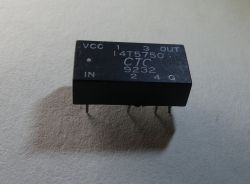
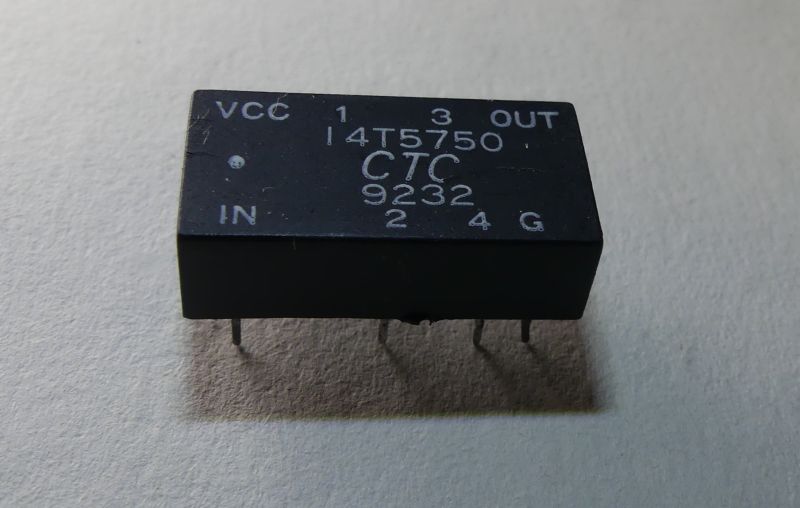
When I visited an electronics colleague recently, he surprised me by putting a small object on the table and asked what the electronic component could be. The component was working on a board in digital circuits. On the casing you will see the markings VCC, GND and OUT. You might suspect that this is some sort of quartz generator, such as DS32KHz or higher frequency generators such as TCXO . Also visible on the chassis is the designation of an input, perhaps controlling the operation of the circuit, and several outputs marked with consecutive numbers.
Do you know what this electronic component is used for?
I was wrongly betting that it was a quartz generator. On old computer motherboards I often saw several generators with different frequencies, usually enclosed in a metal case. Apparently PLL circuits were not used then and it was easier to use several generators with different frequencies.
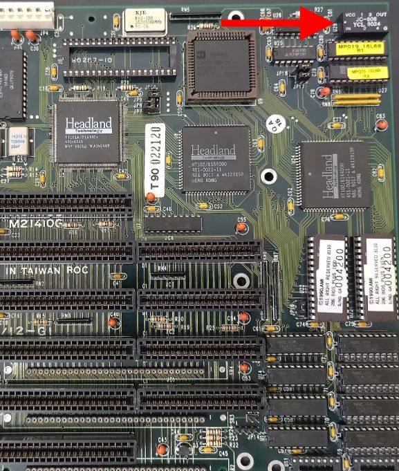
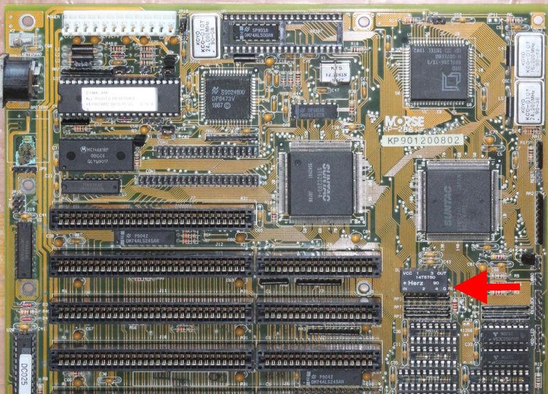
After typing the symbol 14T5750 into google, it was possible to find descriptions of 286 motherboards where this component was used:
https://theretroweb.com/motherboards/s/auva-computer-baby-286-bam-12-g1
https://theretroweb.com/motherboards/s/morse-kp286hf
Below are screenshots from the found pages with the undetermined purpose element highlighted. Miniature DC/DC converters are now available in similar enclosures, but this component is not an inverter.
Managed to find a pdf describing the parameters of this component:
http://www.datasheet.hk/view_download.php?id=1695449&file=0349%5C14t5750_2726584.pdf
It turns out that the manufacturer supplied more models of this component: 14T5750 14HT5750 14HT5125 14HT5251 14HT5500 14T5451 14T5500
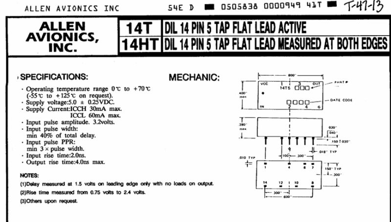
The riddle is explained by the contents of the pdf:
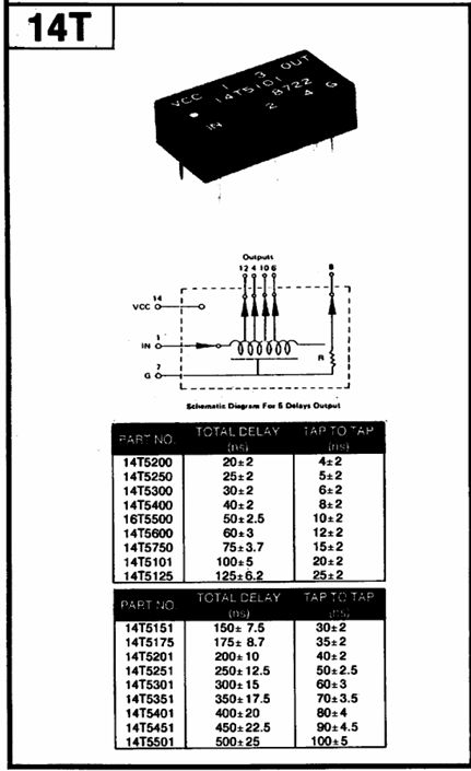
This is a delay line! The circuit is powered by 5V, has an output and several 'taps' with different delays to the input signal. What could such a delay line have been used for on the motherboard of a computer with a 286 processor? I suspect that it was a way of distributing timing signals, with a specific offset/delay of the signal edges. Such an offset may have had applications, for example, in controlling RAM operation. If board schematics with such a line were available, perhaps something could be confirmed.
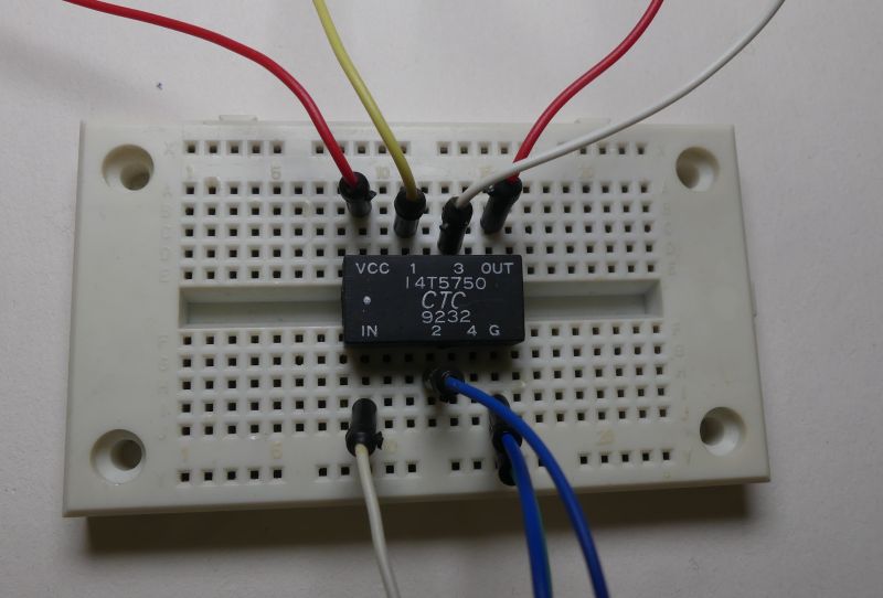
Let's see if the line still works. We supply the circuit with 5V -> current consumption about 17mA. We apply a 100KHz signal to the input and the current consumption increases to about 32mA. It appears that the embedded circuitry in the line is working.
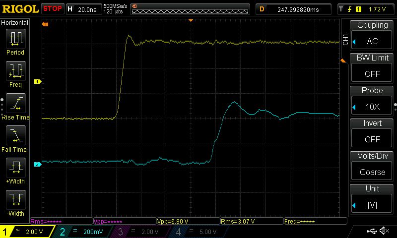
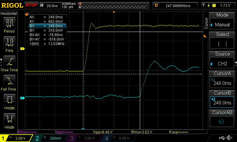
This is what the IN input signal (yellow trace) and the OUT output signal (blue trace) look like. The action of the delay line is visible.
The offset is approximately 76ns according to the parameters in the description.
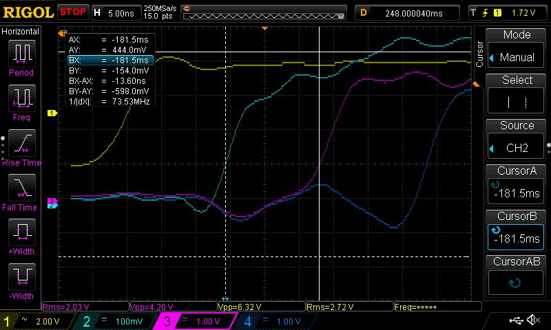
This is what the signals look like on the next "taps" of the line relative to the IN signal:
I was not aware of such a solution for distributing timing signals and delaying digital signals. Although I have seen solutions where gates were used to influence the signal propagation, but then the delay times were shorter.
Have you encountered the use of delay lines in digital devices?
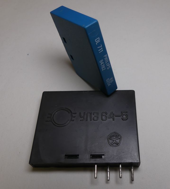
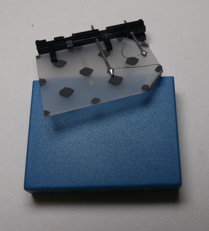
By the way, I am posting pictures of another familiar delay line that was used in analogue TV sets . Specifically, such delay lines were found in PAL decoders. The line delay was 64µs .
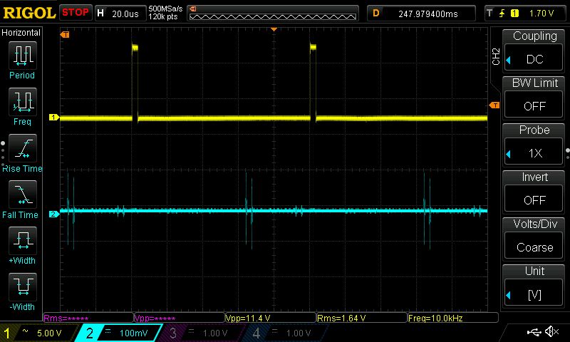
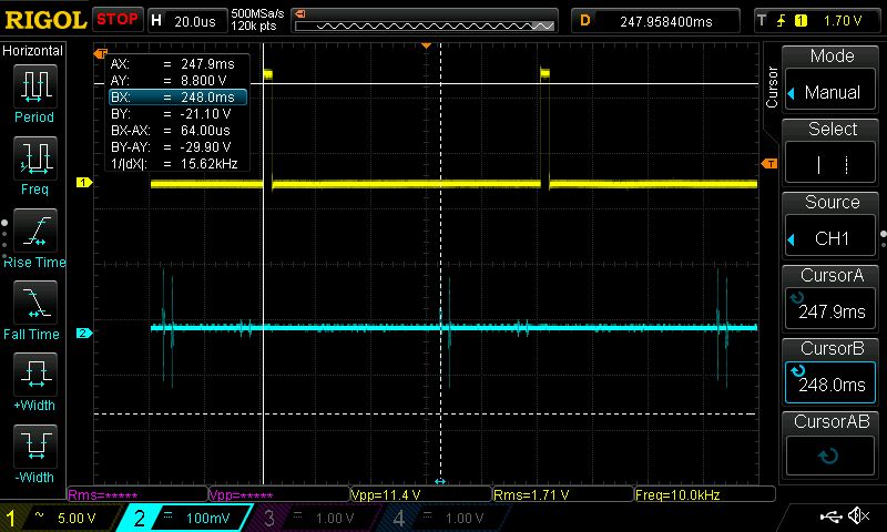
We feed the pulses into the input (yellow trace) and at the output (blue trace) you can observe the pulses appearing with a delay.
The delay is 64µs:
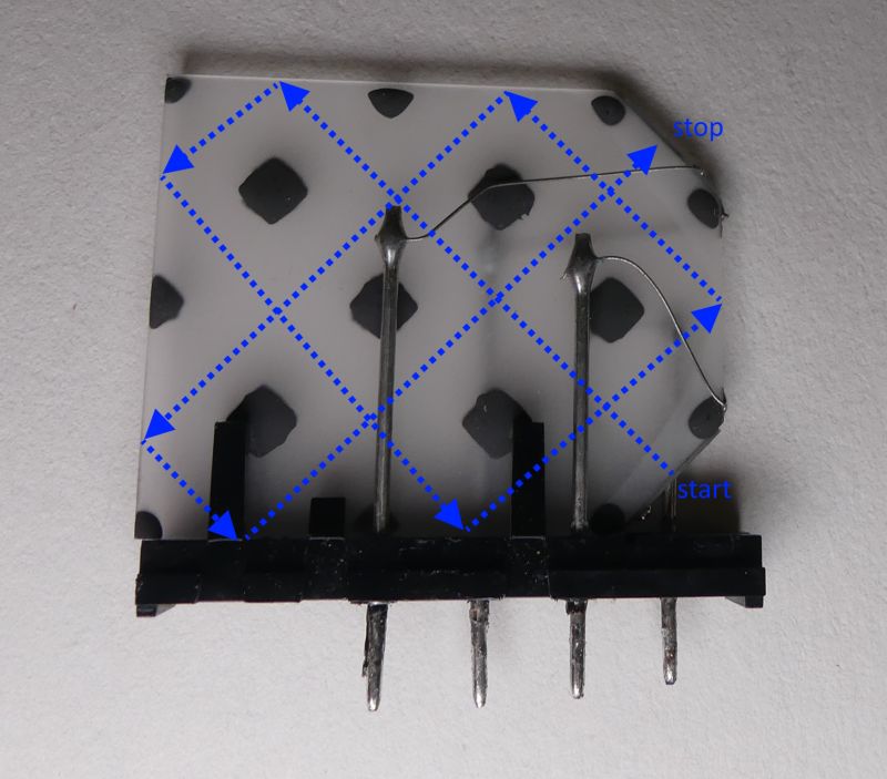
Let's take a look inside the 64µs delay line.
The signal travels a rather complex path in the quartz plate, bouncing at its extremities. Thanks to the multiple reflections, the dimensions of the device can be smaller.
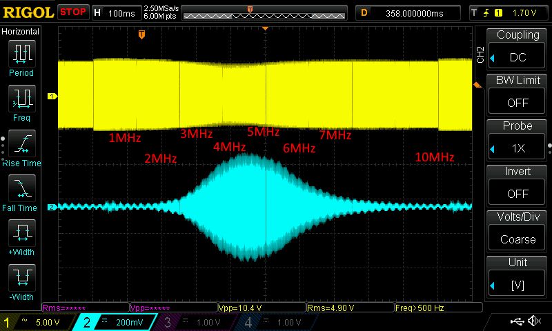
Estimating the frequency response with an oscilloscope and tunable generator , the result is quite predictable, the amplitude peaks between 4-5MHz. You can also see that the line loads the generator output, the amplitude of the input signal varies over a small range.
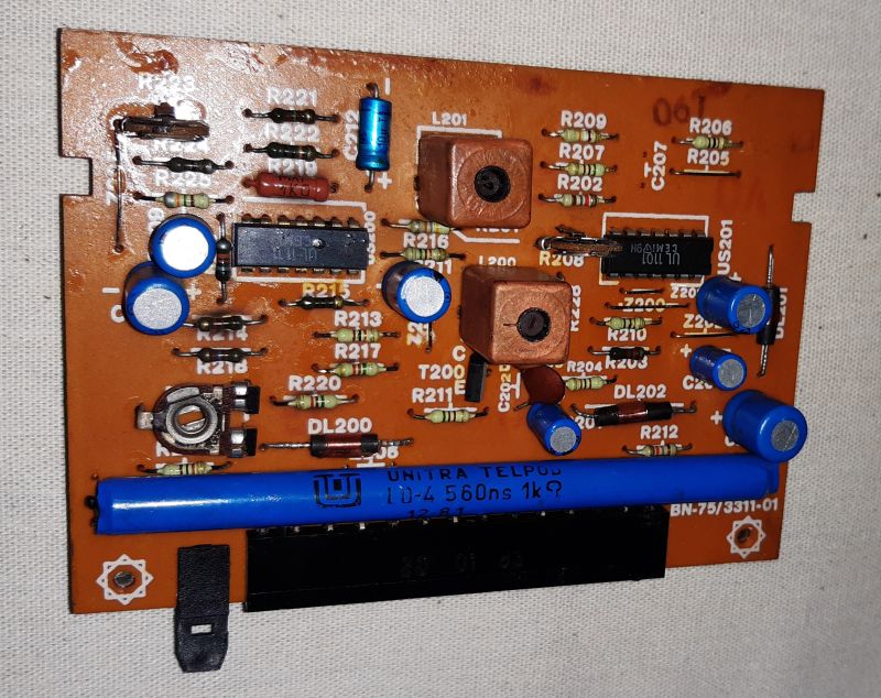
SECAM decoders also included a delay line which was a long thin wire wound around a tube the size of a ballpoint pen. The delay of such a line was less than that of a 64µs line. Below is an example of a module with a 560ns line.
The delay lines used in televisions are still well recognisable, but with the passage of time, like the 14T5750, they can be a puzzling object for their finder.
Delay lines were used in oscilloscopes with a delayed time base. In the early days of computer science and calculating machines, operational memories were built on the basis of delay lines. Bits circulated in a delay line and were re-transmitted to the line after being received. This is how mercury memory worked.


Comments
In digital systems, delay lines were often used to produce the signals necessary to drive dynamic RAMs. [Read more]
An interesting stage where the timing of the RAS/CAS signals was determined by the physical parameters of the soldered-in delay lines. A significant technological leap occurred when configuration was done... [Read more]
Where can such an electronic component be used in DIY projects? [Read more]
Maybe not like this, but e.g. with more delay to produce an echo effect? Delay lines were e.g. mercury memories in the early days of computers. [Read more]
It is rather hard to find a sensible use for these components at the moment, although perhaps I have a poor imagination :) If this delay line can be opened I will also post pictures showing the internal... [Read more]
ad vocem: ''Specifically, such delay lines were found in PAL decoders'' - this ''64us chrominance delay line'' - was in SECAM decoders too !!! ''In SECAM decoders there was also a delay line which was... [Read more]
To date, I cannot write from memory what the 64µs delay line in SECAM and PAL decoders was used for, let alone the 560ns line in a PAL decoder. Maybe one day someone on elektroda.pl will post an article... [Read more]
Not surprisingly.... hardly anyone today knows how decoders work - in fact, only the "old guard" ... while the youngsters don't even have a "drive"... :) The line served precisely to delay the luminance... [Read more]
It is still used, for higher frequencies the delay is realised by tracks on the PCB . [Read more]
Unfortunately you have simplified this considerably. The colour decoders of older TV sets had two delay lines: - 64µs in the chrominance path, processing colour information, - 0.7µs in the luminance... [Read more]
Delay lines were used in devices for encoding voice information using radios and telephone calls. [Read more]
In echo and reverberation circuits, however, it is definitely higher delays that are needed compared to what this line offers. In the old echo and reverberation systems, spring-loaded systems were very... [Read more]
@gregor124 I didn't know that, is this some kind of scrambling? In a typical block or stream encryption, I don't see the need for such a line. @tytka I associate echo with the period after spring reverb... [Read more]
Of more interesting applications, for example, they were used in some very high-speed analogue oscilloscopes, so that you could see, for example, the signal with a delay before the trigger signal appe... [Read more]
In general, the higher the frequency, whether of a mechanical or electromagnetic wave, the shorter the delays. It may be interesting to note how strings were used by Galileo Galilei to discover the laws... [Read more]
I also associate such solutions, And the spring, I had the opportunity to play with quite recently. I had to repair a Pioneer QX-9900, which has reverberation effects realised with such a device. By... [Read more]
This worked on the principle that the signal was split into a number of short time intervals and each section was passed through a different (code-set) delay. The result was that the signal was slightly... [Read more]
Speaking of oscilloscopes - a beautiful and massive (gigantic!) delay line has a Polish oscilloscope made by ZRK OS-150. It consists of several coils of coaxial cable in an outer braid. It looks interesting,... [Read more]
The old memory still works, you need from the received signal to reconstruct three colour signals plus luminance (the one sent in each successive line), in successive lines sent one of the two colours... [Read more]