AM reflex receiver on 2 germanium transistors
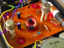
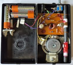
As simple radio receivers are invariably of interest, I have decided to present a rather interesting design for the current technical realities. This is one of the first electronic circuits I had the pleasure of building, but unfortunately, for various reasons it lay unfinished for many years. Recently, looking through my electronic scrapbooks, I found that I had everything I needed to complete it.
The schematic diagram of the radio comes from the book "Radio amateurism at school" by W. Kozak, which was recommended to me by a librarian in primary school when I was in grade 3.
Even then, the material in it was somewhat outdated, as germanium tubes and semiconductors had been superseded by silicon for many years. In addition, the components presented in the book could no longer be obtained and the electronics (radio engineering) presented there had long since passed away. However, I managed to accumulate some germanium semiconductors by dismantling from old equipment and other sources. I started assembling the radio using a flask soldering iron, but progress stopped due to some obstacles with making inductive components.
A scan of the radio's schematic can be seen below. Briefly, it is an AM reflex receiver, on germanium semiconductors: two PNP transistors and one blade diode.
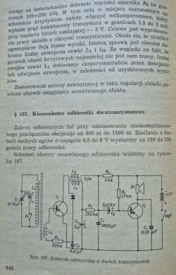
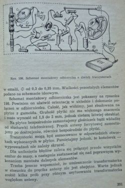

As you can see, the reflex circuit is based on a "w. cz." transformer, which I had the most trouble with because I didn't have a suitable core and attempts to make one from ferrite rod, as described by the author, failed.
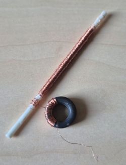
I have now accumulated a number of cores, including toroidal, which are ideal for this purpose. The biggest challenge was winding the right number of coils, which I managed to do by using the right winding method
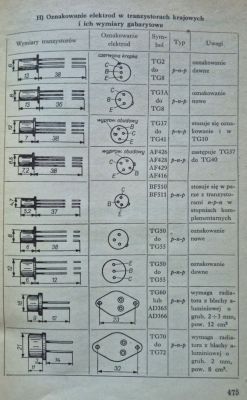
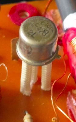
The TG5 transistors have unfortunately been lost somewhere over the years. I used the equivalent AF428 instead of the TG5. There were tables at the end of the book where you could find out about housing types and replacements.
The assembly of germanium semiconductors requires attention, as they are very sensitive to heat. For this reason, I left the 'legs' of the transistors as long as possible. With the diode it was a bit more fun because it turned out that different types of germanium diode give different radio effects. Domestic DOGs were a problem because the radio was agitating, there was no such problem with the Soviet diode found long ago from Rubin, which I finally left.
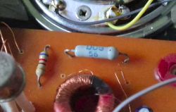
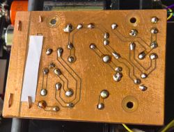
The transformer obviously requires the coils and their ends to be properly connected (which is missing from the schematic).
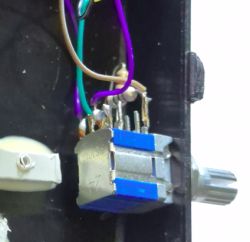
I didn't want to modify the original circuit, which is why there is no additional amplifier, remaining with a single TG50 powering either the speaker or the headphones. This is one of the simplest class A amplifiers, with a sizable DC component flowing through the driver. I used a 50 Ω high-ohm speaker and a 3.5mm stereo jack headphone socket. The headphones are connected in series, which causes them to act in counter-phase, so I reversed the polarity of one of them. While the speaker doesn't play very loudly the headphones are well driven. The power is high enough that I had to use a level control. This is a 4-position switch that switches the radio's power through 30 Ω and 100 Ω resistors.
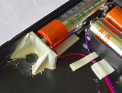
The receiver is powered by three AA batteries in a specially machined space in the case. This configuration establishes the centre of gravity well; there is a speaker on the other side.
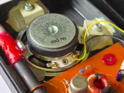
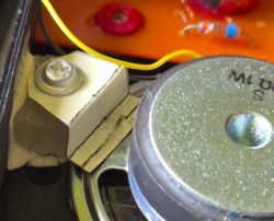
How the radio plays with the loudspeaker is presented in a video from one of this year's recent editions of 'Summer with Radio'.
The radio is very sensitive, 300 km from the RCN transmitter in Solec Kujawski allows listening on headphones in quite good quality. This is due to the rather long ferrite antenna. Initially, when I started up, I heard nothing in the speaker except a rattling sound, which was not a good harbinger. The cause turned out to be an inductive charger running a few metres away.


Comments
Cool project. Respect for sharing at a time when there are thousands of schemes available on the internet and only some of them work. I usually treat the operation of one headphone in counter-phase... [Read more]
For me it's great. For a receiver on two transistors it plays quite nicely. I think I only have the famous ASY37s left of the germanium ones. For winding this toroid I think elongated double-sided forks... [Read more]
:smile: You wrote that the description lacks information on the transformer . For that, your your description from the book is missing two pages :wink: :idea: You do not hold firmly to the... [Read more]
These days, unfortunately, it's more of a curiosity. [Read more]
Well you just ruined the vibe of the old books :( [Read more]
@gps79, @efi222 thanks, it's nice that someone likes it. The winding of the tray could probably be improved, I didn't pay much attention to it, I just took what I had on hand, i.e. a plastic stick, which... [Read more]
:smile: Thank you for the additional pages 👏 🤔 If it would be possible, could you insert a fast diode Shockley diode :idea: :idea: for a test https://obrazki.elektroda.pl/5814915300_1760602225_thumb.jpg... [Read more]
Polish Radio Programme 1 broadcasts on AM? [Read more]
IN AM. That's amplitude modulation, not range (bandwidth). It broadcasts and is doing well, probably as one of the few stations in Poland. I was listening yesterday, PRI is doing quite well from the transmitter... [Read more]
I've done experiments on several receivers with replacing a germanium diode with a Schottky diode (because that's more what you meant). Schottky worked in the detector, but unfortunately worse than germanium... [Read more]
I'm afraid these are too low voltages for a Shockley diode, unless you had a Schottky diode in mind. I've never tried it, maybe I'll test it in my spare time, although it would be easier to test on a detector... [Read more]
at least some of them will be suitable. Will all of them? I don't know. It's worth trying. I once did an experiment and checked if I could use another core found in "junk" instead of the usual ferrite... [Read more]
It depends what function it had, if it was an anti-interference choke it would mean the trafko would have more inductance, and if it was a core from an inverter it might mean it was a powder core designed... [Read more]
I know it's about modulation, but is this reception in AM acceptable/comparable to FM? I ask because I have 2 radios with AM range only: one is some sort of portable, battery-operated Unitra, and the other... [Read more]
Unfortunately they are very different. The FM UKF signal is transmitted at a much higher frequency, requires a different circuit for demodulation than AM, and, most importantly, the UKF signal reaches... [Read more]
It depends on what sound quality you accept. For comfortable understanding of speech, a bandwidth of approx. 2.3 kHz is sufficient ( e.g. SSB modulation, a variation of AM you might say ). 1 P.R. programme... [Read more]
As others have written, the sound quality is inferior to FM, the carrier f is much lower, the AM characteristics also do their bit. The advantage is the range - when I drive across half of Poland and have... [Read more]
I don't really understand this bidding. You might as well say that AM requires no transistor, only a diode. If you can't listen, it's not a full-fledged radio. You yourself showed a schematic of a radio... [Read more]
@e8600 Such a comparison, it's closer to a wire tape recorder aka cassette recorder. Completely different frequency response. [Read more]