logo elektroda
logo elektroda
X

AM reflex receiver on 2 germanium transistors

acctr 3498 41
ADVERTISEMENT
Treść została przetłumaczona polish » english Zobacz oryginalną wersję tematu
📢 Listen (AI):
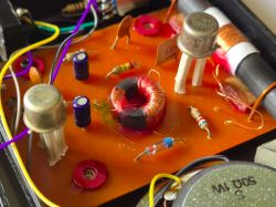
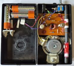
  • Close-up of AM radio circuit board with toroid, germanium transistors, and passive components Inside view of a DIY AM radio with AA batteries, speaker, and electronic components

    As simple radio receivers are invariably of interest, I have decided to present a rather interesting design for the current technical realities. This is one of the first electronic circuits I had the pleasure of building, but unfortunately, for various reasons it lay unfinished for many years. Recently, looking through my electronic scrapbooks, I found that I had everything I needed to complete it.
    The schematic diagram of the radio comes from the book "Radio amateurism at school" by W. Kozak, which was recommended to me by a librarian in primary school when I was in grade 3.
    Even then, the material in it was somewhat outdated, as germanium tubes and semiconductors had been superseded by silicon for many years. In addition, the components presented in the book could no longer be obtained and the electronics (radio engineering) presented there had long since passed away. However, I managed to accumulate some germanium semiconductors by dismantling from old equipment and other sources. I started assembling the radio using a flask soldering iron, but progress stopped due to some obstacles with making inductive components.

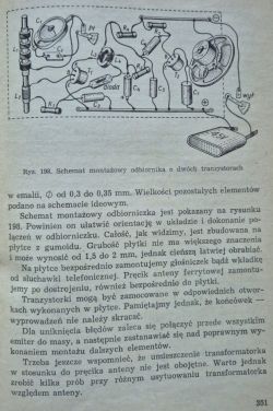
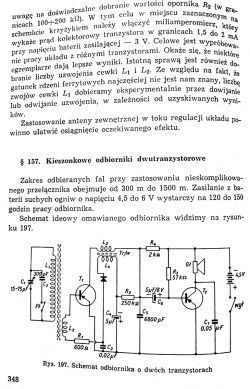
    A scan of the radio's schematic can be seen below. Briefly, it is an AM reflex receiver, on germanium semiconductors: two PNP transistors and one blade diode.

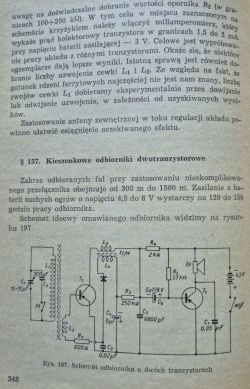
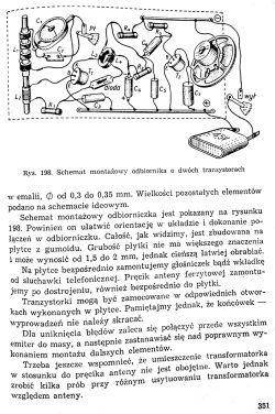
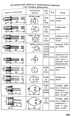
    Book cover of Radioamatorstwo w szkole with illustration of radio and tools. Schematic diagram of a pocket AM radio with two PNP transistors. Assembly diagram of a simple radio receiver using two transistors. Table showing electrode markings and dimensions of germanium p-n-p transistors. Table showing electrode markings and dimensions of germanium p-n-p transistors.

    As you can see, the reflex circuit is based on a "w. cz." transformer, which I had the most trouble with because I didn't have a suitable core and attempts to make one from ferrite rod, as described by the author, failed.
    I have now accumulated a number of cores, including toroidal, which are ideal for this purpose. The biggest challenge was winding the right number of coils, which I managed to do by using the right winding method
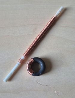
    Two coil cores with copper wire: one ferrite rod and one toroidal core

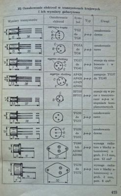
    The TG5 transistors have unfortunately been lost somewhere over the years. I used the equivalent AF428 instead of the TG5. There were tables at the end of the book where you could find out about housing types and replacements.

    The assembly of germanium semiconductors requires attention, as they are very sensitive to heat. For this reason, I left the 'legs' of the transistors as long as possible. With the diode it was a bit more fun because it turned out that different types of germanium diode give different radio effects. Domestic DOGs were a problem because the radio was agitating, there was no such problem with the Soviet diode found long ago from Rubin, which I finally left.
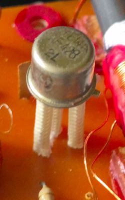
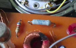
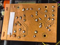
    AF428 germanium transistor on a circuit board with visible wires and thermal insulators Close-up of electronic components including a DOG 56 germanium diode on a circuit board Bottom view of a printed circuit board with soldered joints for an AM radio

    The transformer obviously requires the coils and their ends to be properly connected (which is missing from the schematic).

    I didn't want to modify the original circuit, which is why there is no additional amplifier, remaining with a single TG50 powering either the speaker or the headphones. This is one of the simplest class A amplifiers, with a sizable DC component flowing through the driver. I used a 50 Ω high-ohm speaker and a 3.5mm stereo jack headphone socket. The headphones are connected in series, which causes them to act in counter-phase, so I reversed the polarity of one of them. While the speaker doesn't play very loudly the headphones are well driven. The power is high enough that I had to use a level control. This is a 4-position switch that switches the radio's power through 30 Ω and 100 Ω resistors.
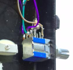
    Close-up of a 4-position rotary switch inside a DIY radio case

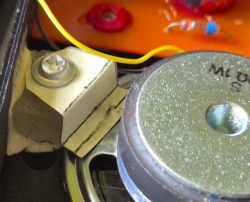
    The receiver is powered by three AA batteries in a specially machined space in the case. This configuration establishes the centre of gravity well; there is a speaker on the other side.
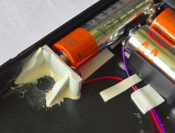
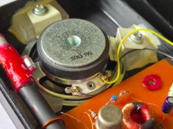
    Close-up of battery compartment in DIY radio with three AA batteries installed. Close-up of AM radio interior with 50 Ω speaker and electronic components. Close-up of speaker unit and plastic mounting bracket with screw inside a radio housing

    How the radio plays with the loudspeaker is presented in a video from one of this year's recent editions of 'Summer with Radio'.


    The radio is very sensitive, 300 km from the RCN transmitter in Solec Kujawski allows listening on headphones in quite good quality. This is due to the rather long ferrite antenna. Initially, when I started up, I heard nothing in the speaker except a rattling sound, which was not a good harbinger. The cause turned out to be an inductive charger running a few metres away.

    Cool? Ranking DIY
    Helpful post? Buy me a coffee.
    About Author
    acctr
    Level 39  
    Offline 
    acctr wrote 4178 posts with rating 1812, helped 369 times. Been with us since 2022 year.
  • ADVERTISEMENT
  • #2 21720012
    gps79
    Level 37  
    Cool project. Respect for sharing at a time when there are thousands of schemes available on the internet and only some of them work.

    acctr wrote:
    The headphones are connected in series, which causes them to operate in counter phase, so I reversed the polarity of one of them.

    I usually treat the operation of one headphone in counter-phase of a mono receiver as an additional feature rather than a disadvantage, as this introduces a pseudo surround to the received sound. Then the sound comes from different directions, rather than from the top of the head as in mono. I know this doesn't suit everyone, but it's good to know that it can still be done.
  • #3 21720421
    efi222
    Level 20  
    For me it's great. For a receiver on two transistors it plays quite nicely. I think I only have the famous ASY37s left of the germanium ones.
    For winding this toroid I think elongated double-sided forks would be better.
  • #4 21720834
    _ACeK_
    Level 13  
    :smile: You wrote that the description lacks information on the transformer . For that, your your description from the book is missing two pages :wink:

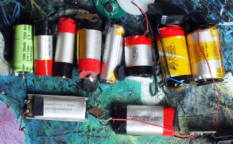
    :idea: You do not hold firmly to the standards of years 60 those (PCB) , then I suggest using Li-ion batteries instead of AA :idea:

    Close-up of various lithium-ion batteries on a colorful textured surface

    ✅ The advantage is that they are free from the donor after the electric cigarette. If on one 3.7V would not want to play, then you can give two in series 7.4V will probably still play louder :lol:

    Btw If you don't mind I've removed the paper from the pages 😇

    Circuit diagram of a two-transistor pocket radio receiver with technical description Assembly diagram of a simple radio using two transistors with labeled components Table of electrode markings and case dimensions for domestic transistors
  • #5 21720841
    ArturAVS
    Moderator
    These days, unfortunately, it's more of a curiosity.
  • ADVERTISEMENT
  • #6 21721198
    Zvirek
    Level 26  
    _ACeK_ wrote:
    Btw If you don't mind I removed the paper from the pages 😇

    Well you just ruined the vibe of the old books :(
  • ADVERTISEMENT
  • #7 21721399
    acctr
    Level 39  
    @gps79, @efi222 thanks, it's nice that someone likes it.
    The winding of the tray could probably be improved, I didn't pay much attention to it, I just took what I had on hand, i.e. a plastic stick, which I easily wound with a wire from some coil with the help of a drill.
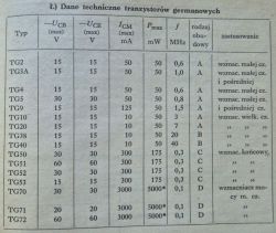
    Germanium transistors are a good bargain at the moment; when such a TG50 NOS classic is priced at under £10 a piece, it's a good bargain. The aforementioned book also gives the parameters of the most popular transistors of the time, and you can compare to the current ones.
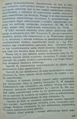
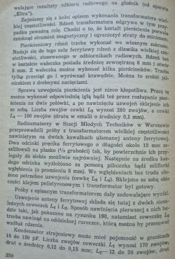
    As someone already mentioned the missing description I add it. There is a fairly detailed description of the receiver operation, number of antenna and transformer coils, etc. You will find that the transistor in the first stage is TG20 (7 MHz) and not, as I wrote, TG5 (0.8 MHz), which was in another receiver from this book and is in the same housing. The reflex circuit requires faster transistors because of the need to amplify two frequencies.

    Technical book page explaining two-transistor radio receiver circuit Book page describing construction of a high-frequency transformer Technical data table of germanium transistors TG2–TG72

    @_ACeK_ keeping the electronics alone in a 60's climate is completely sufficient for me, if the whole thing was done as described, the case would have to be made of wood and the assembly of the components spatial - I didn't particularly care for that. The use of a rechargeable battery is rather pointless, the voltage is too low, there is a need to recharge, with two you need to add a balancer. Probably after some time of disuse it would fizzle out and would have to be replaced, the expected use is one hour of playing per month anyway and the batteries will last for years.

    More about germanium transistors and reflex receivers
    RiK_1964-10, page 242
    https://publikacje.r-kobus.eu/TEWA/TG5.pdf
    https://publikacje.r-kobus.eu/TEWA/TG2.pdf
    Helpful post? Buy me a coffee.
  • #8 21721651
    _ACeK_
    Level 13  
    :smile: Thank you for the additional pages 👏

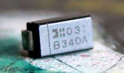
    🤔 If it would be possible, could you insert a fast diode Shockley diode :idea: :idea: for a test

    Close-up of a B340A SMD diode on a circuit board surface

    :arrow: One like the one in the picture I soldered out of a sat tuner, the conduction voltage is 0.178V 😎 I wonder if it would be better than the germanium one 🧐

    🤔 Are all the coils wound with the same diameter wire?

    Close-up of a circuit board with coils, capacitors, and wires

    :idea: In electronics from fluorescent lamps there are sometimes toroidal cores, are these suitable?

    😊 Attached PDF paperless books 🙃
  • #9 21721812
    E8600
    Level 41  
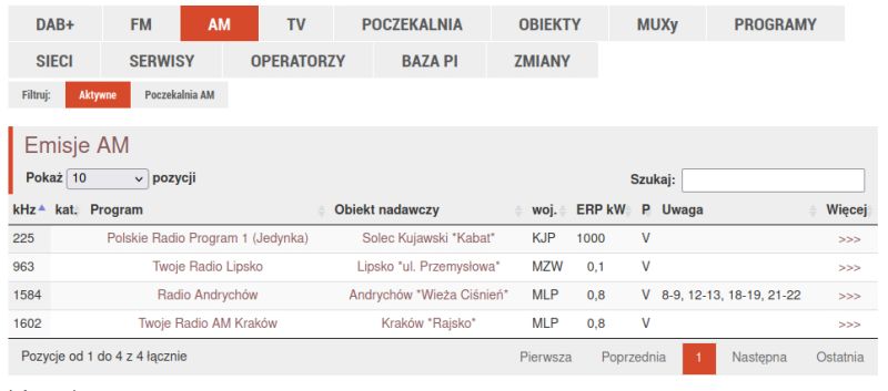
    Polish Radio Programme 1 broadcasts on AM?
  • #10 21721817
    ArturAVS
    Moderator
    E8600 wrote:
    Program 1 of Polish radio broadcasts on AM?

    IN AM. That's amplitude modulation, not range (bandwidth). It broadcasts and is doing well, probably as one of the few stations in Poland. I was listening yesterday, PRI is doing quite well from the transmitter in Solec Kujawski;


    List of active AM broadcasts with four radio stations in Poland
  • #11 21721856
    gps79
    Level 37  
    _ACeK_ wrote:
    I wonder if it would be better than germanium

    I've done experiments on several receivers with replacing a germanium diode with a Schottky diode (because that's more what you meant). Schottky worked in the detector, but unfortunately worse than germanium diodes (which is a pity, as they are more available). Out of luck you could use Schottky diodes, but with the knowledge that the receiver could play better.

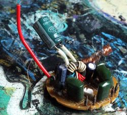
    As for the photo of the compact fluorescent light driver, I solder a coil on a straight ferrite core, which is usually between 2 and 5mH, which is ideal for an HF blocking choke in super-reactive receivers.

    E8600 wrote:
    Program 1 of Polish radio broadcasts on AM?

    It broadcasts both on AM and FM, but is the only nationwide station broadcasting on longwave (225kHz).
  • ADVERTISEMENT
  • #12 21721859
    acctr
    Level 39  
    _ACeK_ wrote:
    Instead of a germanium diode insert a fast Shockley diode

    I'm afraid these are too low voltages for a Shockley diode, unless you had a Schottky diode in mind. I've never tried it, maybe I'll test it in my spare time, although it would be easier to test on a detector receiver, which I can also present.
    E8600 wrote:
    Program 1 of Polish radio broadcasts on AM?

    Yes, almost unchanged and almost uninterrupted for almost 100 years, so that you can build working receivers according to designs from the 20,30, 50 or 60s and enjoy listening to programmes of Programme 1 of the Polish Radio S.A. in liquidation :D
    Helpful post? Buy me a coffee.
  • #13 21721884
    gps79
    Level 37  
    _ACeK_ wrote:
    In electronics from fluorescent lamps there are sometimes toroidal cores, are they suitable?
    at least some of them will be suitable. Will all of them? I don't know. It's worth trying.

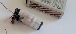
    I once did an experiment and checked if I could use another core found in "junk" instead of the usual ferrite antenna, and it turned out to be yes. I wound the coil on an anti-interference core from a data tape from a printer and surprisingly I was receiving Programme 1 PR on this. The reception was worse than on the longer ferrite antenna, but it was there.
    Improvised antenna with data tape ferrite core next to a matchbox
  • #14 21721901
    acctr
    Level 39  
    _ACeK_ wrote:
    In electronics from fluorescent lamps there are sometimes toroidal cores, are they suitable?

    It depends what function it had, if it was an anti-interference choke it would mean the trafko would have more inductance, and if it was a core from an inverter it might mean it was a powder core designed for energy storage.
    Whether this would affect the coupling in the reflex circuit is hard to say, but it could be as @gps79 wrote.
    In my receiver I used a core from some telecommunications equipment where it worked in a signal transformer.
    Helpful post? Buy me a coffee.
  • #15 21721907
    E8600
    Level 41  
    ArturAVS wrote:
    This is amplitude modulation, not range

    I know it's about modulation, but is this reception in AM acceptable/comparable to FM? I ask because I have 2 radios with AM range only: one is some sort of portable, battery-operated Unitra, and the other is a Russian Falcon in the original cardboard case.
  • #16 21721946
    gps79
    Level 37  
    E8600 wrote:
    is this reception in AM acceptable/comparable to FM?

    Unfortunately they are very different.
    The FM UKF signal is transmitted at a much higher frequency, requires a different circuit for demodulation than AM, and, most importantly, the UKF signal reaches the receiver at up to 1000x less power than the AM long wave signal.
    This is due to the fact that VHF transmitters transmit with a power of a few kW, while, for example, the AM transmitter of Programme 1 of PR transmits with a power of 1MW, as well as the fact that VHF waves are more rapidly attenuated in the atmosphere than long, medium or short waves.

    Added after 5 [minutes]:

    I would also add that for PR1 long wave reception it is possible to make a receiver on 1 transistor, while for UKF reception you already need at least 2-3 transistors. Of course, you need to have a good checked schematic, because there are many non-working ones on the internet.
  • #17 21721953
    AdamC
    Level 29  
    E8600 wrote:

    I know it's all about modulation, but is this reception in AM acceptable/comparable to FM?


    It depends on what sound quality you accept. For comfortable understanding of speech, a bandwidth of approx. 2.3 kHz is sufficient ( e.g. SSB modulation, a variation of AM you might say ). 1 P.R. programme transmitted in AM modulation has a bandwidth of about 6 kHz , and the same programme transmitted in FM modulation has a bandwidth of about 15 kHz.
    I guess you have a radio with ukf 88 - 108 MHz FM and the ones you mentioned, set to that station and compare.
    The rest depends on the workmanship of the receiver, speaker, enclosure.
  • #18 21721982
    acctr
    Level 39  
    E8600 wrote:
    I know it's about modulation, but is this reception in AM acceptable/comparable to FM?

    As others have written, the sound quality is inferior to FM, the carrier f is much lower, the AM characteristics also do their bit. The advantage is the range - when I drive across half of Poland and have 225 kHz set on the radio, the reception does not change at all, just like with FM or DAB.
    Anyway, what's the problem with checking? You wrote that you have a radio with LW range.
    E8600 wrote:
    the other is a Russian Falcon in the original dictky case

    I also have a Falcon, but rather in a solid plastic case.
    gps79 wrote:
    On the other hand, for UKF reception you already need at least 2-3 transistors. Of course, you need to have a good tested schematic, because there are many non-working ones on the internet.

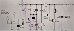
    It is also possible to do on one (not counting the ac amplifier), I did on BF214 and it played normally, another example by A. Janeczek (T2 and T3 are ac amplifiers)
    AM radio circuit diagram using BF199, BC557, and BC547 transistors
    Helpful post? Buy me a coffee.
  • #19 21722001
    gps79
    Level 37  
    acctr wrote:
    On one it is also possible to do (not counting the amplifier of the acoustic part), I did on BF214 and it played normally, another example by A. Janeczek (T2 and T3 are amplifiers of the acoustic part)

    I don't really understand this bidding. You might as well say that AM requires no transistor, only a diode. If you can't listen, it's not a full-fledged radio. You yourself showed a schematic of a radio with 3 transistors.

    Added after 22 [minutes]:

    There is a 50uV signal coming out of the UKF antenna and a 50mV signal coming out of the AM antenna, hence the need for at least one gain stage more for UKF reception.
  • #20 21722158
    ArturAVS
    Moderator
    @E8600 Such a comparison, it's closer to a wire tape recorder aka cassette recorder. Completely different frequency response.
  • #21 21722162
    LEDówki
    Level 43  
    AM transmitters at long and medium wave cut the HF band to 4.5 kHz. UKF transmitters with FM modulation (there is no other in this range as far as radio broadcasting is concerned) have a bandwidth of up to 12 kHz, so there is necessarily more treble. In addition, the higher frequency and FM modulation move interference away from the broadcast. Unfortunately, Chinese products also sow interference in the UKF range. The AM modulated bands (long, medium, short) are more susceptible to interference from converters. It is fortunate that these converters operate at increasingly higher frequencies, moving interference away from long wave. Nobody reports the bugs, so they are imported from the far east and interfere.
  • #22 21722381
    acctr
    Level 39  
    gps79 wrote:
    I don't really understand this bidding. You might as well say that AM requires no transistor, only a diode. If you can't listen, it's not a full-fledged radio. You yourself have shown a schematic of a radio with 3 transistors.

    I could nod or deny that "for UKF reception you already need at least 2-3 transistors", but I have made more than one reaction receiver that consisted of only one transistor, so there is no bidding here, just facts. Anyway, in the post >>21721982 I inserted a schematic where there is a receiver on a single transistor, T2 and T3 form the ac amplifier, without which the receiver would also work.
    gps79 wrote:
    From the UKF antenna comes out a signal of the order of 50uV, and from the AM antenna of the order of 50mV, hence the need for at least one more amplification stage for UKF reception.

    How much signal you get from an antenna depends on the antenna and the distance from the transmitter.
    In general, the claim that such and such modulation requires so many and so many transistors makes no sense, as there will be those who will prove that this is not the case, e.g. the famous case where a Soviet spy room used a piece of metal as an eavesdropper in a foreign embassy.
    Here are examples of FM radios with and without transistors on one transistor


    Here an explanation of this type of FM demodulation


    Helpful post? Buy me a coffee.
  • #23 21722967
    coderemover
    Level 5  
    acctr wrote:
    What signal you get from an antenna depends on the antenna and the distance from the transmitter.

    Let me say more - the power of the transmitter, the distance/propagation and the antenna will determine the *power* of the signal the antenna can deliver to the receiver. And the voltage you get at the antenna depends further on the input impedance of the receiver. A receiver whose input stage is based on a parallel LC resonant circuit has a very high input impedance at tuning, hence the voltage from the antenna can be quite high - orders of hundreds of mV (and that's why it's possible to demodulate it on the diode at all). BTW: respect for a working project!

    acctr wrote:
    In general, the claim that such and such modulation requires so many and so many transistors makes no sense, as there will be those who will prove that this is not the case, e.g. the famous case where a Soviet spy room used a piece of metal as a wiretap in a foreign embassy.


    That's right. I'm building an AM receiver for the umpteenth time now and, paradoxically, my impression is that while AM is trivial to demodulate by-no means (on a diode), such a simple demodulator is very poor - it has terrible linearity, high signal loss and, on top of that, can't cope with selective carrier fading (matters rather more at HF when using a reflected wave). Building a good AM detector is paradoxically perhaps even more complicated than an FM detector and requires at least a phase-coupling loop to extract the carrier.

    LEDówki wrote:
    Also, the higher frequency and FM modulation move interference away from the broadcast.

    You are right that there is generally less interference in the FM radio band than in the lower bands - all those pulse chargers don't get that high. However, it is not quite so with this modulation - FM modulation is somewhat less susceptible to interference in radio broadcasting, because it uses a much wider bandwidth - and the same information is encoded redundantly on many frequencies (the spectrum of a signal modulated by a single tone has many widely spaced striations, in AM there are only two). In the FM radio band you could fit 2,000 AM stations into a standard 4.5 kHz audio bandwidth, or about 500 stations, assuming full bandwidth up to 16 kHz. However, if you were to set a level playing field and compare AM and FM at the same bandwidth, I already have considerable doubt that FM would be better.

    There is also a second reason: many popular portable receivers have the AM band treated negligently. For example, the very fact of using a simple envelope detector already means that you have an SNR 3 dB worse than with a synchronous detector. A great deal also depends on the characteristics of the filters.

    E.g. aviation uses AM en masse in the UKF band because of the *greater* immunity of this modulation to interference.
    You can hear AM even if you have noise stronger than the signal and you can hear something there. If two are transmitting on AM simultaneously, you'll hear both of them too. FM has the disadvantage that if you have a signal too weak, you won't hear anything, and you'll only hear one of the two superimposed transmissions.

    LEDówki wrote:
    UKF transmitters with FM modulation (there is no other in this range as far as radio is concerned) have a bandwidth of up to 12 kHz

    At least 16 kHz. Limiting the bandwidth to 12 kHz would be silly and just waste bandwidth, because you have a stereo pilot signal on 19 kHz anyway. In fact, you can get as close to 19 kHz as your anti-aliasing filters will allow. As long as you don't interfere with the pilot itself and nothing goes above 19 kHz, it's ok.

    gps79 wrote:
    and, most importantly, the UKF signal reaches the receiver with up to 1000x less power than the AM long wave signal.
    This is due to the fact that VHF transmitters transmit with a power of a few kW, while, for example, the AM transmitter of Programme 1 of the Polish Radio broadcasts with a power of 1MW, as well as the fact that VHF waves are more rapidly attenuated in the atmosphere than long, medium or short waves.


    That how? But you know you're comparing a transmitter broadcasting to the whole of Poland and a chunk of Europe with stations with the range of one large city?
    Signal strength depends strongly on the distance from the transmitter. On FM UKF transmits with low power, but the distance you have from the transmitter is generally much smaller than for that one Polish station transmitting on LW. In sum, the power of the signal reaching the receiver is similar, unless you live right next to the mast in Solec Kujawski. BTW: I've just checked - the UKF signal in my city is actually very strong - often at -50 to -70 dBm. FM is so strong that until I installed proper decent input filters in my AM receiver, FM stations magically materialised for me on shortwave (via heterodyne harmonics).

    The other thing is UKF is not attenuated in the atmosphere, because if it were then aviation would not operate on UKF ;)
    UKF has a short range because:
    - it penetrates less well through terrain obstacles (houses, trees)
    - it does not bend on the curvature of the ground; in practice you have to see the transmitter to receive the signal - a transmitting antenna behind the horizon means no signal - this
  • #25 21723863
    acctr
    Level 39  
    _ACeK_ wrote:
    There is a description of a modern "crystal detector" without a diode

    You can see that a solid ferrite antenna means reception is good too.
    I recently took on a turn-of-the-century tower with LW and MW bands, without the internal ferrite antenna but with an input for an external frame antenna. Whether the reception is better, I don't know.
    Helpful post? Buy me a coffee.
  • #26 21724570
    efi222
    Level 20  
    acctr wrote:
    You can see that a solid ferrite antenna means that reception is also good.

    It is also worth adding that a ferrite antenna is a directional antenna and should be positioned perpendicular to the direction of the transmitter.
  • #27 21725271
    _ACeK_
    Level 13  
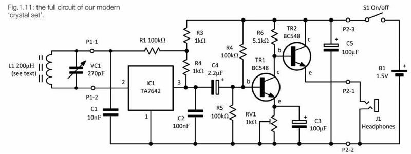
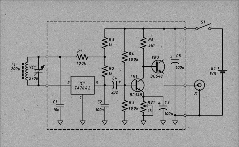
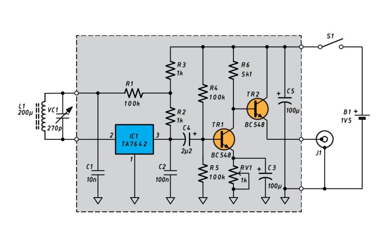
    :smile: Posted schematic above ⬆️ from Practical Electronics may someone not like it because of :arrow: © 🤔
    :oops: It's just in case I made a copy :idea: In US you're not allowed to take photos in court 👀 but no one forbids making drawings :lol:
    ✅ To satisfy all cyclists, retros, computer users there are two versions 🙃

    ⬇️ First with paper 😇

    AM radio circuit diagram with TA7642 IC and BC548 transistors

    ⬇️ Second with colour 😎
    AM radio circuit diagram with TA7642 IC, BC548 transistors and coil L1
    :idea: The radio itself is for medium wave 700 kHz to 1.6 MHz ⚠️ Coil L1 has 54 coils of wire with a diameter of 0.55 mm 🧐

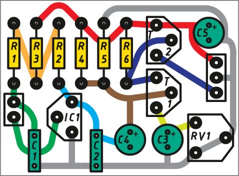
    Colorful PCB layout diagram with labeled electronic components and traces

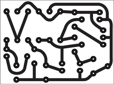
    Black PCB trace layout diagram on a white background

    :smile: PCB :evil:


    😊 Back to the diode question Schottky 🙃
    ⬇️ The one in the photo

    Close-up of a B340A SMD diode on a circuit board surface

    :idea: There is a rectifying diode 3A 40V where the drop at the junction at 3A is 500mV . Checking with a meter at current probably 1 mA has a drop of only 178 mV so I'm curious how it will behave at higher frequencies 🤔
  • #28 21726112
    PPK
    Level 30  
    I also used to mount it on the TG8, TG50 but the problem was colossal interference.
  • #29 21726208
    żarówka rtęciowa
    Level 38  
    Hello

    With a little reworking you could use silicon transistors e.g. BF214 and BC211 instead of germanium transistors for the diagram in the first post.
  • #30 21726336
    acctr
    Level 39  
    żarówka rtęciowa wrote:
    With minor modifications, silicon transistors could be used

    Probably yes, an AM radio can be made in dozens if not hundreds of ways. Here I am just presenting one particular implementation, distinguished by the fact that the design as well as the key elements date back to the 1960s. Otherwise, I would not be motivated to build and present here a receiver on silicon transistors, even made by CEMI.
    Helpful post? Buy me a coffee.
📢 Listen (AI):
ADVERTISEMENT