Adapter for rapid programming of WBR3 Wi-Fi modules (design and 3D printing, pogo pins)
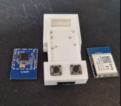
WBR3 is a distinctive Wi-Fi module based on the W701-VA2-CG (RTL8720CF) chip. The WBR3 is distinguished by the fact that the necessary signals for its programming are located only on its underside, making it necessary to solder the module off the board for firmware changes. Additionally, its programming requires as many as 7 signals, which makes it worth the struggle to simplify the process. Here I will show how we achieved this.
First, I will remind you how we used to program the WBR3:
1. first the module must be soldered off the board (with hot air)
2. then the 7 wires are soldered
3. then we desolder these wires and the module is back in place
Stage 2/3 is shown in our video:
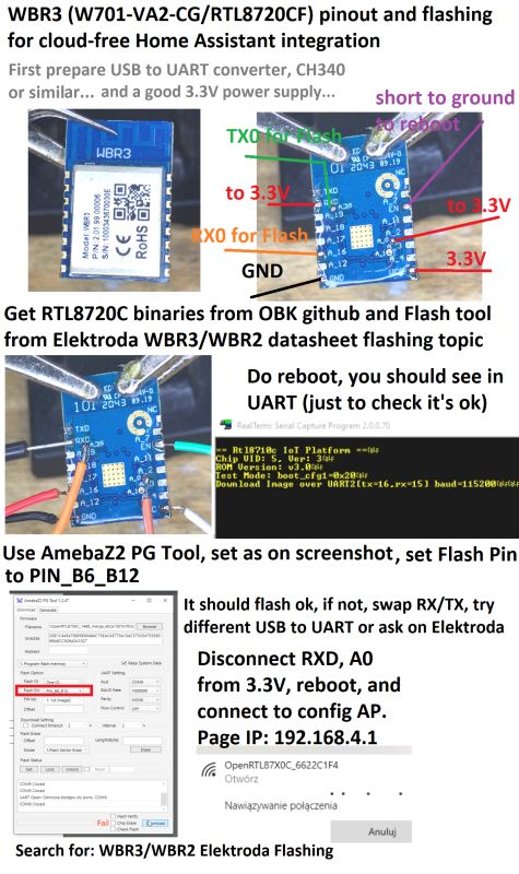
Recently, however, @DeDaMrAz has been reworking quite a few WBR3-based devices, hence the need to simplify the process. The idea was to make an adapter that allows an already soldered WBR3 module to be programmed without additional soldering. The module still needs to be removed from the board, but the rest of the process is greatly simplified. We started by dimensioning the board:
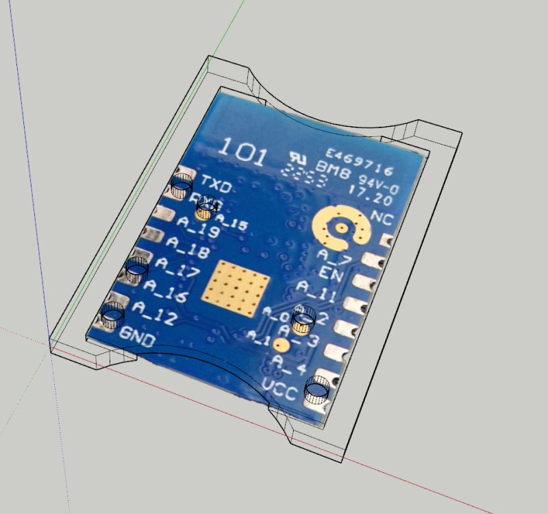
Then the adapter was modelled - several versions were tested, below is the final one:
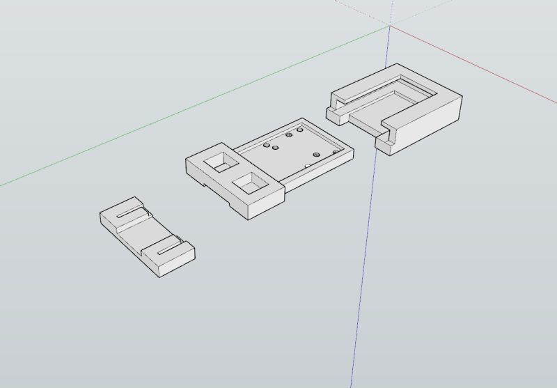
The holes are for the BOOT and RESET buttons.
However, you still need to take care of the contact with the pads. The pogo pins are used for this:
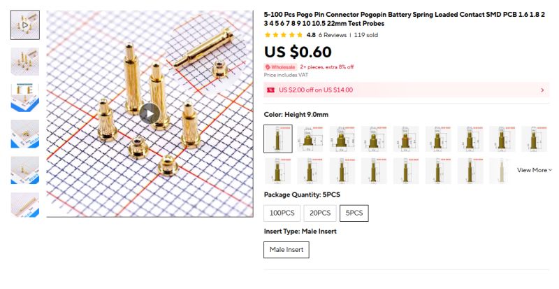
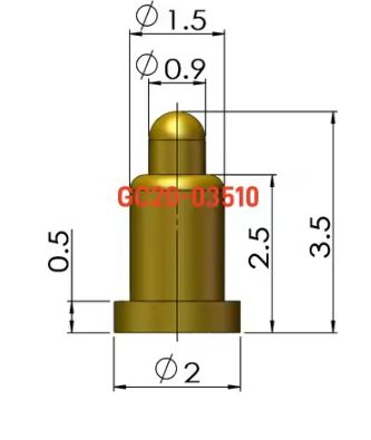
These pins come in different versions, but all have a built-in spring - this ensures good contact with the pad. We chose the 3.5mm high version:
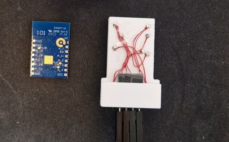
All this has been suitably connected inside the adapter:
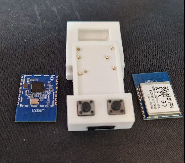
The completed adapter and two WBR3 modules (one with the screen removed):
Adapter together with programmable module:
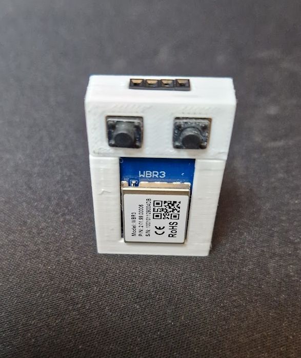
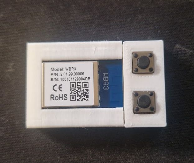
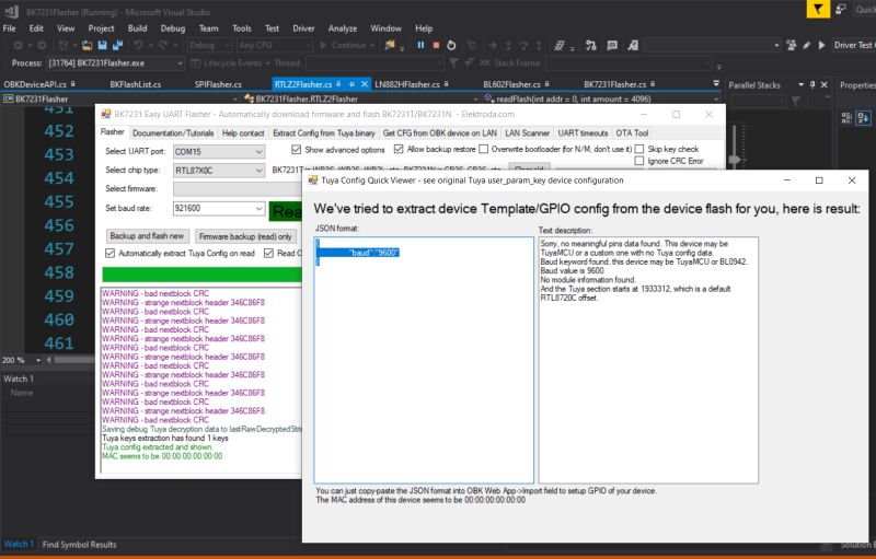
We used our flasher to test the adapter:
https://github.com/openshwprojects/BK7231GUIFlashTool
It correctly reads and programs the RTL87X0C:
That's basically it - from now on we can conveniently upload our open source software .
In summary , the WBR3 Wi-Fi module is distinguished from other modules (WB3S, TYWE3S, CB3S, etc.) by the fact that it has the necessary programming signals brought out on pads available only on its bottom. This makes it necessary, firstly, to solder it off the board before changing the firmware and, secondly, to solder cables to it separately, of which there are also quite a few here. The requirement to solder it off the PCB is unlikely to be helped (because how else to get to the signals? Unless, of course, to remove the screen and get to the QFN?), but we managed to speed up the next stage considerably. Instead of soldering the wires, all we need to do is use our adapter. The matter is made all the easier by the fact that no bonding or cleaning of its pads is needed to desolder and solder the WBR3 in place, so the whole thing can happen quite quickly, as long as you have some basic experience of working with hot air. In this way, we have been able to significantly speed up the cloud release of WBR3-based IoT devices.
Have you also encountered the WBR3 module? Or perhaps you are familiar with another similar situation where a proprietary adapter from pogo pins can speed up the work?


Comments