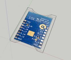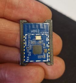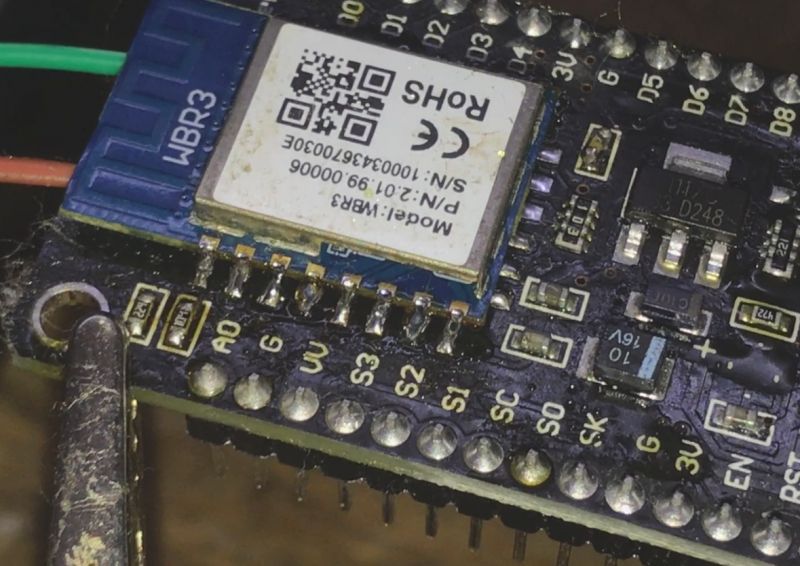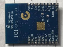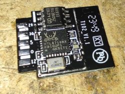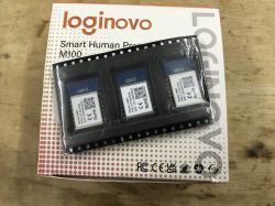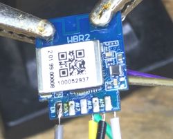
Here's step by step flashing and HA Discovery guide for W701-VA2-CG (RTL8720CF)-based Tuya modules that can be programmed with AmebaZ2 PG Tool 1.2.47 (download included). This way you can run those devices cloud free, use it with Tasmota commands (Tasmota Remota app), and add new features like sensors, scripts, and so on.
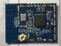
This guide is applicable to the following modules with the core chip of RTL8720CF or similar, so: WBR1, WBR2, WBR3, WBR2L, WBR3L, WBRU etc.
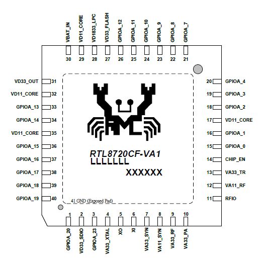
Datasheet:
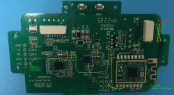
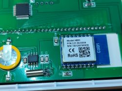
See sample device teardown with WBR2: [WBR2/W701] Unsupported MaxCom Smart Breaker SHSB111W10
Here is a sample boot log taken from Log UAR T pins of similar device:
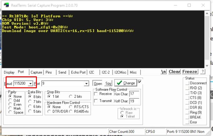
== Rtl8710c IoT Platform ==
Chip VID: 5, Ver: 3
ROM Version: v3.0
Test Mode: boot_cfg1=0x20
Download Image over UART2[tx=16,rx=15] baud=115200

== Rtl8710c IoT Platform ==
Chip VID: 5, Ver: 3
ROM Version: v3.0

== Boot Loader ==
Dec  5 2019:14:02:18

fwx SELE[fffffffe]
fw SELE Bitidx 1, fw1 valid 1, sn 100, fw2 valid 1, sn 101
fw2 USE, return sn 101

Boot Loader <==

== RAM Start ==
Build @ 14:44:45, Jul 29 2020

 Create Task init, stack 0x1000fb28, len 5120

 Create Task app_init, stack 0x10010f88, len 8192

 Create Task IDLE, stack 0x10012fe8, len 768

 Create Task Tmr Svc, stack 0x10013640, len 2048

 Create Task TCP_IP, stack 0x10013fb8, len 4000
interface 0 is initialized
interface 1 is initialized

In[01-01 18:12itializing :15 TUYA InfWIFI ...o][mqc_app.c:175] mqc app init ...

 Create Task sys_timer, stack 0x1001a800, len 4096

 Create Task cmmod, stack 0x1001eca8, len 4096
[01-01 18:12:15 TUYA Info][sf_mqc_cb.c:42] register mqc app callback
[01-01 18:12:15 TUYA Debug][mqc_app.c:118] mq_pro:5 mqc_handler_cnt:1
[01-01 18:12:15 TUYA Debug][mqc_app.c:118] mq_pro:31 mqc_handler_cnt:2
[01-01 18:12:15 TUYA Debug][log_seq.c:732] read from uf. max:0 first:0 last:0
[01-01 18:12:15 TUYA Debug][svc_online_log.c:288] svc online log init success

 Create Task wk_th-0, stack 0x10023e18, len 5120
[01-01 18:12:15 TUYA Err][tuya_ws_db.c:314] kvs_read fails gw_bi -1
[01-01 18:12:15 TUYA Err][ws_db_gw.c:111] gw base read fails -935
[01-01 18:12:15 TUYA Debug][tuya_bt_sdk.c:89] ty bt cmmod register finish 1
[01-01 18:12:15 TUYA Notice][tuya_ble_api.c:301] ble sdk inited
[01-01 18:12:15 TUYA Debug][tuya_hal_bt.c:1047] tuya_hal_bt_port_init

[01-01 18:12:15 TUYA Debug][uni_thread.c:215] Thread:sys_timer Exec Start. Set to Running Status
[01-01 18:12:15 TUYA Debug][uni_thread.c:215] Thread:cmmod Exec Start. Set to Running Status
[01-01 18:12:15 TUYA Debug][uni_thread.c:215] Thread:wk_th-0 Exec Start. Set to Running Status

 Create Task rtw_recv_tasklet, stack 0x10025328, len 5936

 Create Task rtw_xmit_tasklet, stack 0x10026b68, len 1024

 Create Task rtw_interrupt_thread, stack 0x10027078, len 1024

 Create Task cmd_thread, stack 0x10027588, len 2048

WIFI initialized

init_thread(55), Available hea
 Createp 0x16be0 Task trace_task, stack 0x10027ef8, len 512

 Create Task UpperStackTask, stack 0x100287c8, len 3072

 Create Task HCI I/F, stack 0x1002b2b0, len 2048
BT BUILD Date: Jul 29 2020, 16:17:09
BT RESET LOG...
[01-01 18:12:15 TUYA Debug][tuya_hal_wifi.c:575] read wifi mac:38:1f:8d:39:13:c2
[01-01 18:12:15 TUYA Notice][tuya_hal_bt.c:893] BLE MAC: 0x38-0x1f-0x8d-0x39-0x13-0xc2

 Create Task tuya_bt_main_task, stack 0x1002c3d8, len 2560
BT Reset ok
bt_iqk_efuse_valid: has data

hci_tp_phy_efuse[0]=0,
bt_dump_iqk:    DUMP,
the IQK_xx  data is 0x127,
the IQK_yy  data is 0x3fe,
the QDAC   data is 0x1a,
the IDAC   data is 0x1b,
the QDAC2  data is 0x19,
the IDAC2  data is 0x19,

 Create Task rtw_coex_mailbox_thread, stack 0x1000fc08, len 1024
hci_read_rom_check: rom_version 0x0003, bt_hci_chip_id 0x0004

BT ADDRESS:
38:1f:8d:39:13:c2:

 WRITE  physical FLATK=tx_flatk=ff00

We use fw_buf=1002f128, fw_len = 13a0, config_buf = 10010128, config_len= 32
Set baudrate to 921600

hci_tp_config:BT INIT success 7
Start upperStack
[01-01 18:12:15 TUYA Debug][tuya_hal_bt.c:788] tuya_bt_app_profile_callback(), service_id:255, tuya_bt_srv_id:1

[01-01 18:12:15 TUYA Debug][tuya_hal_bt.c:338] tuya_bt_handle_io_msg(), msg_type:0

[01-01 18:12:15 TUYA Debug][tuya_hal_bt.c:239] app_handle_gap_msg: subtype 1

[01-01 18:12:15 TUYA Debug][tuya_hal_bt.c:72] app_handle_dev_state_evt: init state 1, adv state 0, cause 0x0


[BLE peripheral] GAP stack ready
[01-01 18:12:15 TUYA Debug][tuya_hal_bt.c:338] tuya_bt_handle_io_msg(), msg_type:0

[01-01 18:12:15 TUYA Debug][tuya_hal_bt.c:239] app_handle_gap_msg: subtype 1

[01-01 18:12:15 TUYA Debug][tuya_hal_bt.c:72] app_handle_dev_state_evt: init state 1, adv state 1, cause 0x0

[01-01 18:12:15 TUYA Debug][tuya_hal_bt.c:338] tuya_bt_handle_io_msg(), msg_type:0

[01-01 18:12:15 TUYA Debug][tuya_hal_bt.c:239] app_handle_gap_msg: subtype 1

[01-01 18:12:15 TUYA Debug][tuya_hal_bt.c:72] app_handle_dev_state_evt: init state 1, adv state 2, cause 0x0

[01-01 18:12:15 TUYA Debug][tuya_hal_bt.c:91] GAP adv start

[01-01 18:12:15 TUYA Notice][tuya_ble_api.c:337] ble sdk re_inited
[01-01 18:12:15 TUYA Notice][tuya_bt_sdk.c:130] ty bt sdk init success finish
[01-01 18:12:15 TUYA Notice][tuya_main.c:396] Base firmware: rtl8720cf_tls_common_iot_config:2.1.6 compiled at Date:Jul 29 2020 Time:16:17:40
[01-01 18:12:15 TUYA Notice][tuya_main.c:397] reset reset reason num 0
[01-01 18:12:15 TUYA Debug][tuya_device.c:19] < TUYA IOT SDK V:1.0.12 BS:40.00_PT:2.2_LAN:3.3_CAD:1.0.2_CD:1.0.0 >
< BUILD AT:2020_07_28_19_56_28 BY embed FOR ty_iot_wf_bt_sdk_rtos AT rtl8720cf_ameba >
IOT DEFS < WIFI_GW:1 DEBUG:1 KV_FILE:0 SHUTDOWN_MODE:0 LITTLE_END:1 TLS_MODE:2 ENABLE_LOCAL_LINKAGE:0 ENABLE_CLOUD_OPERATION:0 ENABLE_SUBDEVICE:0 ENABLE_ENGINEER_TO_NORMAL:0 OPERATING_SYSTEM:2 ENABLE_SYS_RPC:0 TY_SECURITY_CHIP:0 RELIABLE_TRANSFER:RELIABLE_TRANSFER ENABLE_LAN_ENCRYPTION:1 ENABLE_LAN_LINKAGE:0 ENABLE_LAN_LINKAGE_MASTER:0 >

[01-01 18:12:15 TUYA Debug][tuya_device.c:20] rtl8720cf_tls_common_iot_config:2.1.6
[01-01 18:12:15 TUYA Notice][simple_flash.c:430] key_addr: 0x1d8000   block_sz 4096
[01-01 18:12:15 TUYA Notice][simple_flash.c:498] get key:
0x52 0x32 0x7c 0x62 0xcc 0x45 0x99 0xbc 0x1f 0x80 0x21 0xa7 0xfa 0x6 0xbe 0x6c
[01-01 18:12:15 TUYA Notice][tuya_main.c:447] have actived over 15 min, not enter mf_init
[01-01 18:12:15 TUYA Notice][tuya_uart_common_api.c:118] ty_uart_common_main_components_version:1.0.5,memrory left:67400...
[01-01 18:12:15 TUYA Notice][uart_common.c:238] pConfig = {low_sw:close,wifi_bdrate:115200,wifi_cofig_ver:1.0.0,crc:13,}---config len:62
[01-01 18:12:15 TUYA Notice][flash_config.c:192] ty_uart_public_iot_table_read_component_version:1.0.0
[01-01 18:12:15 TUYA Notice][flash_config.c:160] key:wifi_cofig_ver,value:1.0.0,len:5
[01-01 18:12:15 TUYA Notice][flash_config.c:157] key:wifi_bdrate,value:115200,len:3
[01-01 18:12:15 TUYA Notice][flash_config.c:167] key:low_sw,value:0,len:1
[01-01 18:12:15 TUYA Err][flash_config.c:129] json key 'flow_sw' not exist!
[01-01 18:12:15 TUYA Err][flash_config.c:129] json key 'ir_sw' not exist!
[01-01 18:12:15 TUYA Err][flash_config.c:129] json key 'ir_tx' not exist!
[01-01 18:12:15 TUYA Err][flash_config.c:129] json key 'ir_rx' not exist!
[01-01 18:12:15 TUYA Notice][uart_common.c:122] get_config_flow_sw err.
[01-01 18:12:15 TUYA Notice][uart_common.c:138] get_config_ir_sw err.
[01-01 18:12:15 TUYA Notice][uart_common.c:170] uart badrate:115200
[01-01 18:12:16 TUYA Notice][uart_common.c:171] flow_open:0
[01-01 18:12:16 TUYA Notice][uart_common.c:172] lowpower_open:0
[01-01 18:12:16 TUYA Notice][uart_common.c:173] ir_open:0
[01-01 18:12:16 TUYA Notice][uart_common.c:174] ir_tx:2
[01-01 18:12:16 TUYA Notice][uart_common.c:175] ir_rx:3
[01-01 18:12:16 TUYA Notice][tuya_uart.c:134] 0   115200

 Create Task ty_uart_task, stack 0x1002f128, len 4096
[01-01 18:12:16 TUYA Notice][uart_common.c:748] uart_task_init ok
[01-01 18:12:16 TUYA Notice][weather_sever.c:348] ty_uart_public_weather_component_version:1.0.0
[01-01 18:12:16 TUYA Notice][tuya_download_file.c:630] ty_uart_public_file_download_component_version:1.0.0
[01-01 18:12:16 TUYA Notice][tuya_download_file.c:662] file_download_init OK
[01-01 18:12:16 TUYA Notice][tuya_uart_common_api.c:186]  tuya_uart_common_init ok,memrory left:60624...
[01-01 18:12:16 TUYA Notice][process_server.c:110] send jump_pack
[01-01 18:12:18 TUYA Notice][uart_common.c:631] heart timer out clear all
[01-01 18:12:19 TUYA Notice][process_server.c:110] send jump_pack
[01-01 18:12:21 TUYA Notice][uart_common.c:631] heart timer out clear all
[01-01 18:12:22 TUYA Notice][process_server.c:110] send jump_pack
[01-01 18:12:24 TUYA Notice][uart_common.c:631] heart timer out clear all
[01-01 18:12:25 TUYA Notice][process_server.c:110] send jump_pack
[01-01 18:12:27 TUYA Notice][uart_common.c:631] heart timer out clear all
[01-01 18:12:28 TUYA Notice][process_server.c:110] send jump_pack
[01-01 18:12:30 TUYA Notice][uart_common.c:631] heart timer out clear all
[01-01 18:12:31 TUYA Notice][process_server.c:110] send jump_pack
Source: https://www.elektroda.com/rtvforum/topic4093142-60.html#21361625
Yes, I know it says Rtl8710c, rtl8720c is just 8710 with bluetooth.
For this guide, you will need to have some basic soldering skills and a USB to UART converter, like the CH340 one. It should have 3.3V voltage levels. So far, I've been using successfully this one for years:
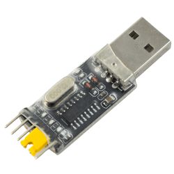
I am also often using external 3.3V LDO (like AMS1117-3.3V) as a better power supply. 3.3V directly from USB to UART may not work. The 3.3V pin on shown USB to UART converter is only used to select voltage levels.
W701-VA2-CG modules
Let's consider most popular W701-VA2-CG modules.
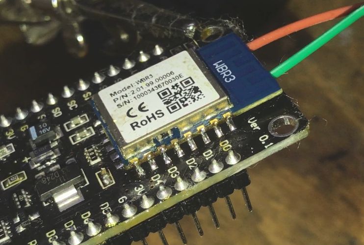
WBR3 is a common Tuya module based on W701-VA2-CG. It has somewhat similar footprint to popular TYWE3S (ESP12) modules, so it also matches more or less with CB3S and WB3S.
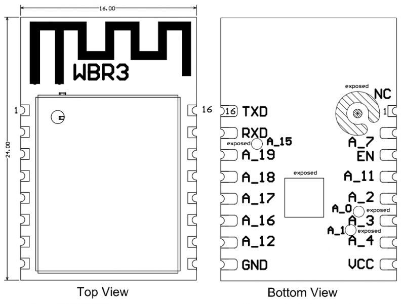
| Pin number | Symbol | I/O type | Function | 1 | NC | / | The pin is pulled up to be compatible with other modules | 2 | A_7 | I/O | GPIOA_7, hardware PWM, IC Pin 21 | 3 | EN | I/O | Enabling pin, which works at the high level and is pulled up and controlled by a user externally | 4 | A_11 | I/O | GPIOA_11, hardware PWM, IC Pin 25 | 5 | A_2 | I/O | GPIOA_2, hardware PWM, IC Pin 18 | 6 | A_3 | I/O | GPIOA_3, hardware PWM, IC Pin 19 | 7 | A_4 | I/O | GPIOA_4, hardware PWM, IC Pin 20 | 8 | VCC | P | Power supply pin (3.3V) | 9 | GND | P | Power supply reference ground | 10 | A_12 | I/O | GPIOA_12, hardware PWM, IC Pin 26 | 11 | A_16 | I/O | GPIOA_16, UART_Log_TXD, which is used for displaying the module internal information and can be configured as a common GPIO | 12 | A_17 | I/O | GPIOA_17, hardware PWM, IC Pin 38 | 13 | A_18 | I/O | GPIOA_18, hardware PWM, IC Pin 39 | 14 | A_19 | I/O | GPIOA_19, hardware PWM, IC Pin 40 | 15 | RXD | I/O | GPIOA_13, UART0_RXD, which is used as a user-side serial interface pin | 16 | TXD | I/O | GPIOA_14, UART0_TXD, which is used as a user-side serial interface pin |
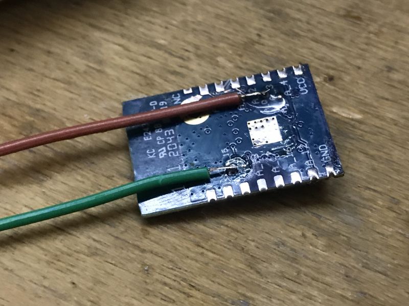
There is also A_15 (UART_Log_RXD) available on the back of the module.
WBR2 is a common Tuya module based on W701-VA2-CG. It has somewhat similar footprint to popular TYWE2S (ESP8266) modules, so it also matches more or less with CB2S and WB2S.

| Pin number | Symbol | IO type | Function | 1 | 3V3 | / | Power supply pin (3.3V) | 2 | A19 | I/O | GPIOA_19, hardware PWM, IC Pin40 | 3 | GND | P | Power supply reference ground | 4 | A18 | I/O | GPIOA_18, hardware PWM, IC Pin39 | 5 | A13 | I/O | GPIOA_13, UART0_RXD, which is used as a user-side serial interface pin | 6 | A17 | I/O | GPIOA_17, hardware PWM, IC Pin38 | 7 | A14 | I/O | GPIOA_14, UART0_TXD, which is used as a user-side serial interface pin | 8 | A20 | I/O | GPIOA_20, common GPIO, IC Pin1 | 9 | A12 | I/O | GPIOA_12, hardware PWM, IC Pin26 | 10 | EN | I/O | Enabling pin, which works at the high level and is pulled up and controlled by a user externally | 11 | A11 | I/O | GPIOA_11, hardware PWM, IC Pin25 |
There is also A_15 (UART_Log_RXD) and A_16 (UART_Log_TXD) available on the back of the module.
WBRU is a common Tuya module based on W701-VA2-CG. It has somewhat similar footprint to CBU, with both UART ports available on sides.
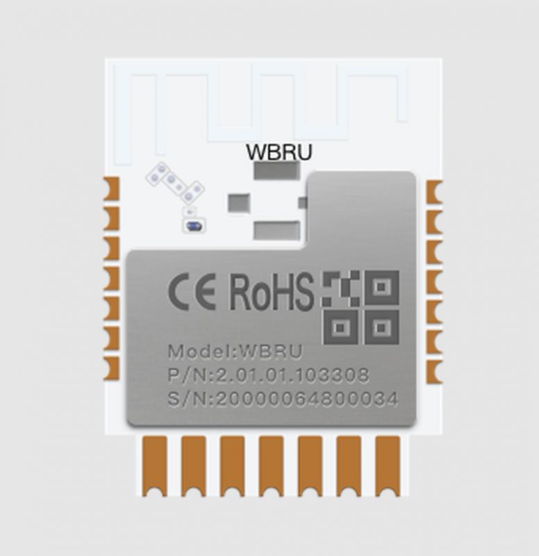
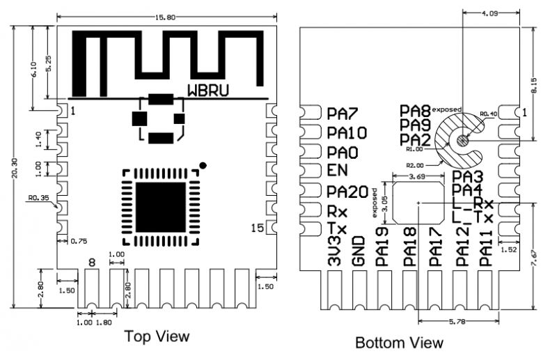
| Pin number | Symbol | II/O type | Function | 1 | PA8 | I/O | GPIOA_8, common GPIO, which can be reused as SPI_SCK and corresponds to Pin 22 of the IC | 2 | PA9 | I/O | GPIOA_9, common GPIO, which can be reused as SPI_MOSI and corresponds to Pin 23 of the IC | 3 | PA2 | I/O | GPIOA_2, hardware PWM, correspond to Pin 18 of the IC | 4 | PA3 | I/O | GPIOA_3, hardware PWM, correspond to Pin 19 of the IC | 5 | PA4 | I/O | GPIOA_4, hardware PWM, correspond to Pin 20 of the IC | 6 | L_RX | I/O | GPIOA_15, UART_Log_RXD (used to receive the external logs of the module), which can be configured as a common GPIO | 7 | L_TX | I/O | GPIOA_16, UART_Log_TXD (used to send the internal logs of the module), which can be configured as a common GPIO | 8 | PA11 | I/O | GPIOA_11, hardware PWM, correspond to Pin 25 of the IC | 9 | PA12 | I/O | GPIOA_12, hardware PWM, correspond to Pin 26 of the IC | 10 | PA17 | I/O | GPIOA_17, hardware PWM, correspond to Pin 38 of the IC | 11 | PA18 | I/O | GPIOA_18, hardware PWM, correspond to Pin 39 of the IC | 12 | PA19 | I/O | GPIOA_19, hardware PWM, correspond to Pin 40 of the IC | 13 | GND | P | Power supply reference ground | 14 | VCC | P | Power supply pin (3.3V) | 15 | TX | I/O | GPIOA_14, UART0_TXD (user serial interface) | 16 | RX | I/O | GPIOA_13, UART0_RXD (user serial interface) | 17 | PA20 | I/O | GPIOA_20, common GPIO, correspond to Pin 1 of the IC | 18 | EN | I/O | Enabling pin, active at the high level. The module has been pulled to the high level and the user can control the pin externally | 19 | PA0 | I/O | GPIOA_0, not recommend to pull it to the high level. If it is pulled to a high level, it will enter the test mode. Correspond to Pin 15 of the IC | 20 | PA10 | I/O | GPIOA_10, common GPIO, which can be reused as SPI_MISO and corresponds to Pin 24 of the IC | 21 | PA7 | I/O | GPIOA_7, common GPIO, which can be reused as SPI_CS and corresponds to Pin 21 of the IC |
NOTE: A_15 (UART_Log_RXD) and A_16 (UART_Log_TXD) are used as debug log output and as flashing port. A_13 (UART0_RXD) and A_0 must be pulled high to enable bootloader.
Update 2026
As of 2026, this platform read/write is also supported by our flash tool:
https://github.com/openshwprojects/BK7231GUIFlashTool
The connection (soldering, wires), is the same, but you can use our tool instead of the legacy one.
Please check it out and use it instead of legacy tools, let us know how it works for you!
Flashing guide
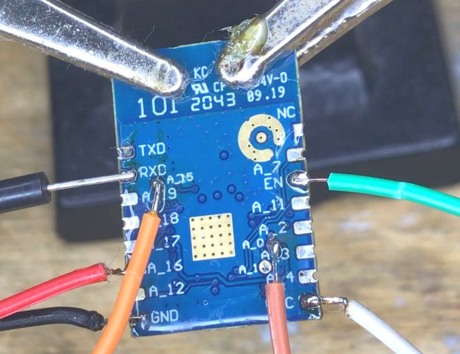
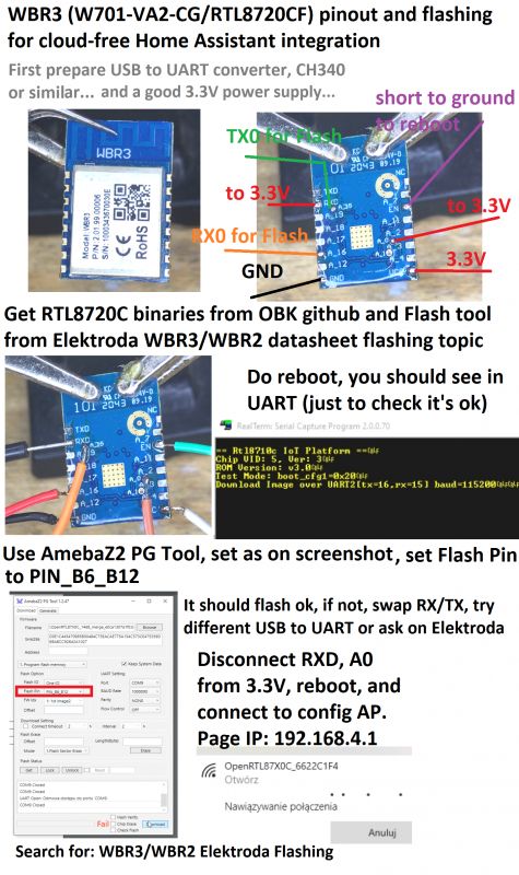
Those WBR3/WBR2 modules are strange, in case of WBR3 you need to access pin from under module. You can desolder it with hot air.
You need to connect:
- GND and 3.3V to a good 3.3V power supply
- A_16 to USB to UART RX
- A_15 to USB to UART TX (it's on module back)
- RXD and A0 to 3.3V (to enable bootloader mode)
To reset module, connect EN to ground (it's like RESET, CEN pin)
This is how it looks like for WBR3:
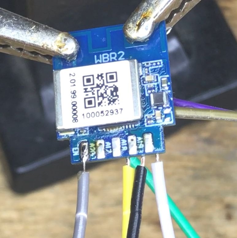
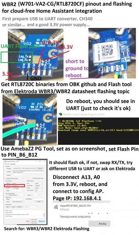
And for WBR2:
- GND and 3.3V to a good 3.3V power supply
- LOG_TX to USB to UART RX
- LOG_RX to USB to UART TX (it's on module back)
- A13 (RXD) and A0 to 3.3V (to enable bootloader mode)
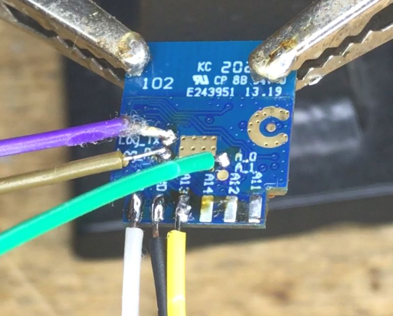
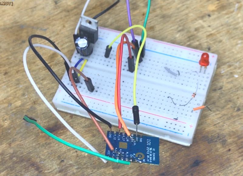
Here is my setup, as you can see I am using TC1264 (similar to AMS1117-3.3V) LDO for power supply:
Get our binaries here:
https://github.com/openshwprojects/OpenBK7231T_App
Now, if you run any UART to USB converter, you should be able to see this message after doing reboot (shorting EN to ground for a moment):
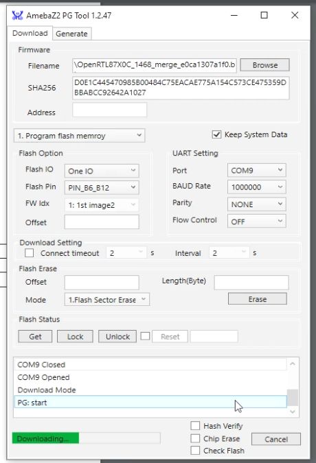
Now you can use AmebaZ2 PG Tool 1.2.47:
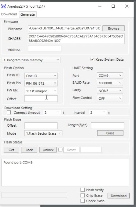
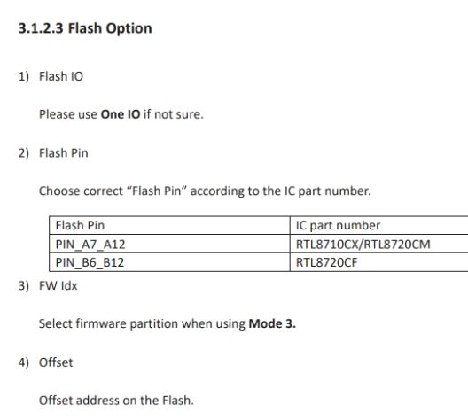
Set Flash Pin as in Docs:
Start flashing:
Remember that you need to disconnect booting pins from 3.3V (all except 3.3V pin itself) and reboot in order for new firmware to start.
To sum up - flashing infographics, WBR3:
WBR2:
Tuya flashing docs:
Binaries and flash Tool download
Get binaries from our repository:
https://github.com/openshwprojects/OpenBK7231T_App
Navigate to Releases tab:
https://github.com/openshwprojects/OpenBK7231T_App/releases
Binaries are marked as RTL87X0C, OpenRTL87X0C, they should run on RTL8710C/RTL8720C:
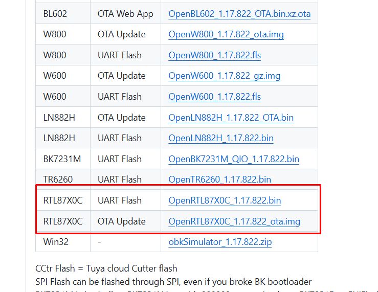
Flash tool is available here:
Flash tool mirror is here:
https://github.com/openshwprojects/FlashTools/tree/main/Realtek
First configuration
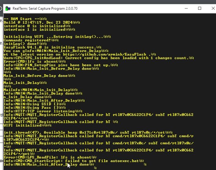
So now you have flashed your device and disconnected pulled up signals from 3.3V. Of course, the main 3.3V pin still should be connected, because your device needs power. Short EN to ground to reboot. Then first thing to check is the UART log output. It should print OBK log correctly:
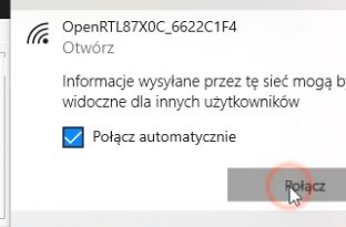
OBK access point should appear:
Connect to this AP and go to 192.168.4.1:
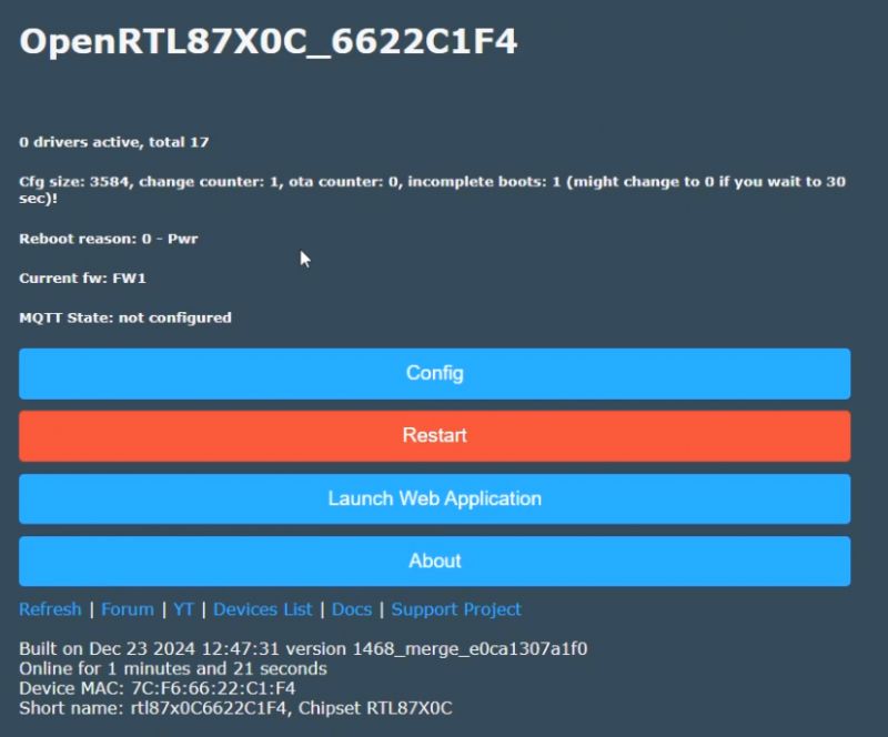
Go to config, WiFi:
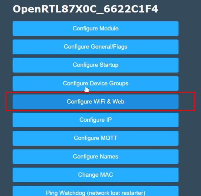
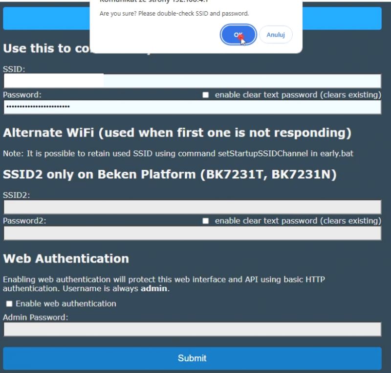
Configure your WiFi SSID/password there.
Device will reboot and connect to your network. You can use your router DHCP clients list to discover new device IP.
What to do next?
With OBK you can do many things, including HASS Discovery:
Use SSDP Discovery:
Use Tasmota Device Groups:
Add DHT11:
Create custom online builds and drivers:
How to create a custom driver for OpenBeken with online builds (no toolchain required)
OpenBeken online building system - compiling firmware for all platforms (BK7231, BL602, W800, etc)
OBK repository:
https://github.com/openshwprojects/OpenBK7231T_App
OBK docs:
https://github.com/openshwprojects/OpenBK7231T_App/blob/main/docs/README.md
Our devices list:
https://openbekeniot.github.io/webapp/devicesList.html
Interesting development board
There is also BW15 module available along with development board. It features RTL8720CF. More info coming soon.
Summary
Ameba ZII is now flashable with OBK. WBR3/WBR2/etc modules requires few more wires to flash, but it's still doable. WBR3 may be a bit more problematic, because flashing pads are on the back of the module, but you can always desolder whole module with hot air. Even a cheap hot air station like 858 should work good. Soon we will also release a video showing whole process step for step, but that's all for now. Good luck with flashing your devices!
Special thanks for @insmod and @divadiow for RTL porting and testing!
PS: I also attach some futher RTL8720-related dasheets... there are more RTL types that we hope to support soon as well.
Cool? Ranking DIY Helpful post? Buy me a coffee.


