A simple simulation of the MAX7219 matrix display - how I speed up the creation of clock controller
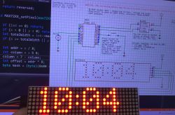
Recently I reactivated the project of a network synchronised clock based on the MAX7219 display and additional sensors, but the work was effectively slowed down by the lack of free space on the table and the long time waiting for compilation and uploading firmware to the board. For this reason, I started looking for an alternative solution, the basis of which I had in principle already prepared - it turned out to be a clever way of running the MAX7219 on a Windows platform. Here I will briefly describe the implementation and operation of my idea.
Introduction
I wrote the project with a number of platforms in mind in our environment OpenBeken , which at the moment supports the platforms shown in the table below (as of 2025.11.22):
Spoiler:
| Platform | Family | WPA3 | OTA | GPIO | GPIO IRQ | UART | PWM | ADC | Deep sleep | WDT | SPI LED | IR | BK7231T | Beken | ✅¹² | ✅ | ✅ | ✅ | ✅ | ✅ | ✅ | ✅ | ✅ | ✅¹² | ✅ | BK7231N | Beken | ✅¹² | ✅ | ✅ | ✅ | ✅ | ✅ | ✅ | ✅ | ✅ | ✅ | ✅ | BK7231U | Beken | ✅ | ✅¹ | ✅ | ✅ | ✅ | ✅ | ✅ | ✅ | ✅ | ✅ | ✅ | BK7238 | Beken | ✅ | ✅ | ✅ | ✅ | ✅ | ✅ | ✅ | ✅ | ✅ | ✅ | ✅ | BK7252 | Beken | ✅ | ⚠️¹'¹⁴ | ✅ | ✅ | ✅ | ✅ | ✅ | ✅ | ✅ | ✅ | ✅ | BK7252N | Beken | ✅ | ✅ | ✅ | ✅ | ✅ | ✅ | ✅ | ✅ | ✅ | ✅ | ✅ | XR809 | XRadio | ❌ | ❌⁵ | ✅ | ✅ | ✅ | ✅⁸ | ✅ | ✅ | ✅ | ❌ | ❌ | XR806 | XRadio | ✅ | ✅ | ✅ | ✅ | ✅ | ✅⁸ | ✅ | ✅ | ✅ | ❌ | ❌ | XR872/XF16 | XRadio | ✅ | ✅² | ✅ | ✅ | ✅ | ✅⁸ | ✅ | ✅ | ✅ | ❌ | ❌ | BL602/LF686 | Bouffalo Lab | ✅ | ✅⁴ | ✅ | ✅ | ✅ | ✅ | ❌ | ✅ | ✅ | ✅ | ✅ | W800/W801 | Winner Micro | ❌ | ✅ | ✅ | ✅ | ✅ | ✅ | ✅ | ❌ | ✅ | ❌ | ❌ | W600/W601 | Winner Micro | ❌ | ✅ | ✅ | ✅ | ✅ | ✅ | ✅ | ❌ | ✅ | ❌ | ❌ | LN882H | Lightning Semi | ✅ | ✅⁴ | ✅ | ✅ | ❌ | ✅ | ❗️ | ❌ | ✅ | ✅ | ✅ | ESP8266 | Espressif | ⚠️¹³ | ✅²'⁴ | ✅ | ✅ | ✅ | ✅⁷ | ❌ | ❗️ | ❓⁹ | ❌ | ❌ | ESP32 | Espressif | ⚠️¹³ | ✅⁴ | ✅ | ✅ | ✅ | ✅ | ❓ | ✅¹⁰ | ✅ | ✅ | ❌ | TR6260 | Transa Semi | ❌ | ❗️³'⁴ | ✅ | ✅ | ❌ | ✅⁸ | ❌ | ❌ | ✅⁹ | ❌ | ❌ | RTL8711AM (Ameba1) | Realtek | ❗️ | ✅⁴ | ✅ | ✅ | ✅ | ✅⁸ | ❌ | ❌ | ✅ | ✅ | ❌ | RTL8710B (AmebaZ) | Realtek | ✅ | ✅⁴ | ✅ | ✅ | ✅ | ✅⁸ | ❌ | ❌ | ✅ | ✅ | ❌ | RTL8720C (AmebaZ2) | Realtek | ✅ | ✅⁴ | ✅ | ✅ | ✅ | ✅⁸ | ➖ | ❌ | ✅ | ✅ | ✅ | RTL8720CS (AmebaCS) | Realtek | ✅ | ✅⁴ | ✅ | ✅ | ✅ | ✅⁸ | ❌ | ❌ | ✅ | ✅ | ❗️ | RTL8711DAF (AmebaDplus) | Realtek | ✅ | ✅ | ✅ | ✅ | ✅ | ✅ | ❌ | ❌ | ✅ | ✅ | ❗️ | RTL8710ECF (AmebaLite) | Realtek | ✅ | ✅ | ✅ | ✅ | ✅ | ✅ | ❌ | ❌ | ✅ | ✅ | ❗️ | ECR6600 | ESWIN | ✅ | ✅ | ✅ | ✅ | ✅ | ✅⁸ | ❗️ | ❗️¹¹ | ✅ | ❌ | ❌ | TXW81X | Taixin | ❌ | ❗️ | ✅ | ❓ | ❌ | ❌ | ❌ | ❌ | ❓ | ❌ | ❌ | RDA5981 | RDA | ❌ | ✅ | ✅ | ✅ | ✅ | ✅ | ❌ | ❌ | ✅ | ➖ | ❌ |
The board is too big, so I put it in the spoiler.
I prototyped on the board shown on the forum two years ago:
Clock on ESP12 and MAX7219 display - tutorial - part 1, ArduinoOTA, basics
[size=18] How to run MAX7219 on Windows?
My firmware already has a port to Windows - potentially just need to use it:
OpenBeken IoT device simulator - first early alpha version for testing
Only that the MAX7219 is not yet supported there. One would have to wonder how it could be simulated there, although I must stress beforehand that Simulator is more of a household name - it is not an emulator of any kind, it is a firmware port to Windows.
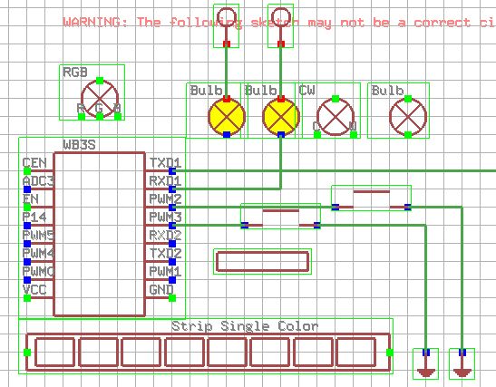
It would probably be best to implement this at the signal level - that is, probably perform a logic step with each change of the associated pins from SPI. This would read the bits and then assemble them into bytes and eventually parse and handle the commands like the MAX7219 does.
Unfortunately, this would require a bit of work - for this reason, I've decided to assume for now that there will be one MAX7219 and ignore its connections in the Simulator. Instead, I am sending the information to its pixel level:
Code: C / C++
I receive this data in the Simulator and draw "pixels" conditionally based on it:
Code: C / C++
It is only important to remember that the pixels are grouped by 64 (one MAX7219 supports 64 diodes) and to respect the order of the matrix rows/columns.
Of course, I also need to separately generate the MAX7219 (quadruple) object in the Simulator, but that is beyond the scope of this topic. For information, I will add that the Simulator is realised in SDL with OpenGL based on its own classes that also support writing, reading and editing of objects.
Presentation of effects
We start by adding a display object - for now there is only a quadruple version:
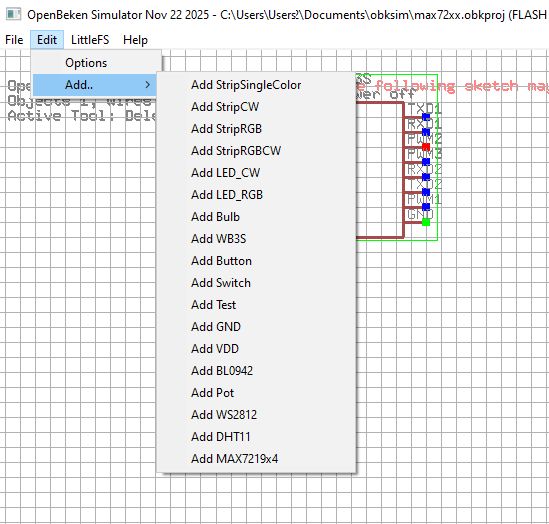
We get the object - at this point it doesn't need to be connected. This is obviously a flaw, but I'll fix that in part two:
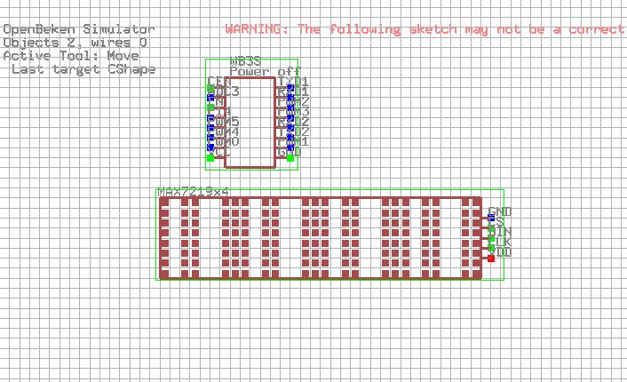
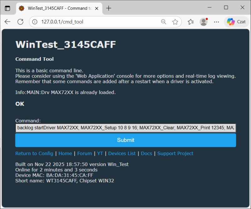
Now you can access the web panel of the virtual device and operate the MAX72XX controller at will, just as if you were doing it on a physical Wi-Fi module. For example, you could try to display some text:
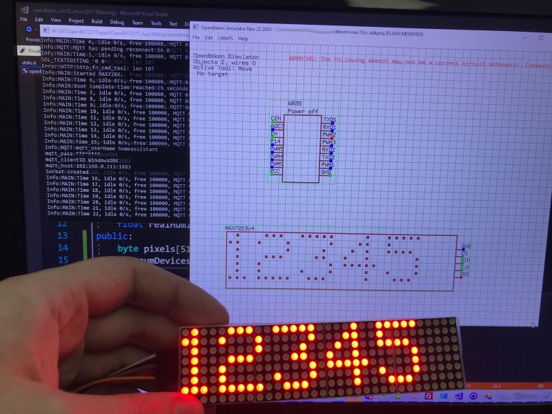
I fired an identical command on an ESP8266 with a physical display module. The effect in both cases is the same:
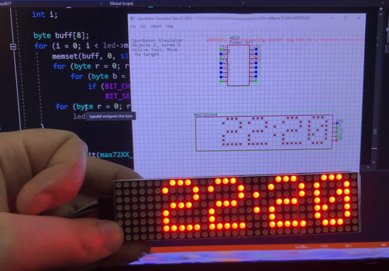
Similarly, the clock driver with time taken from the network via NTP, also behaves the same on both platforms:
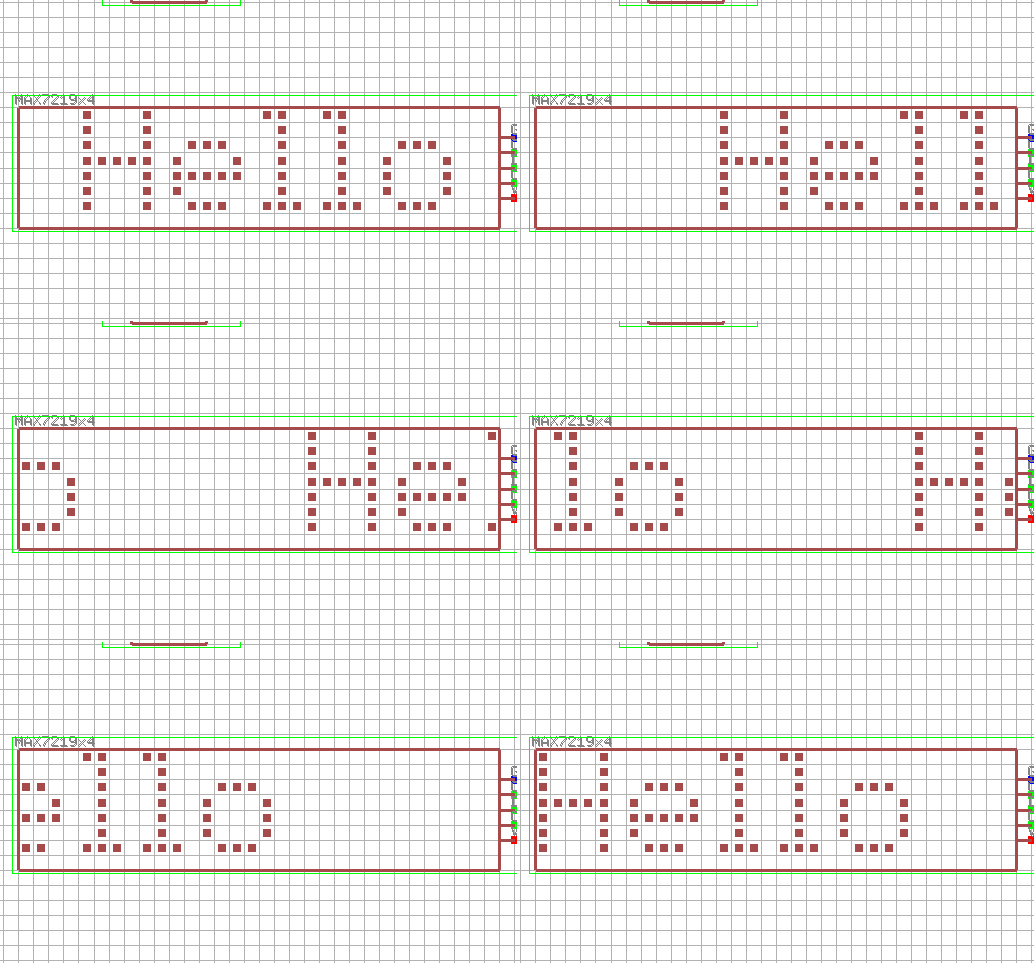
In a similar way, the Berry scripts now work - consider the simplest example:
autoexec = module("autoexec")

def myLogic()
      runCmd("MAX72XX_Scroll 1")
      runCmd("MAX72XX_refresh")
end

runCmd("startDriver MAX72XX")
runCmd("MAX72XX_Setup 10 8 9 5")
runCmd("MAX72XX_Clear")
runCmd("MAX72XX_Print Hello")
setInterval(myLogic, 100)

return autoexec
Then more advanced scripts can be tested:
test = module("test")

def pad2(n)
      if n < 10 return "0" + str(n) end
      return str(n)
end

def myLogic()
      time = gmtime("YMDhms")
      Y = time[0]
      M = time[1]
      D = time[2]
      h = time[3]
      m = time[4]
      s = time[5]
      runCmd("MAX72XX_Clear")
      runCmd("MAX72XX_Print " + pad2(h) + ":" + pad2(m))
      runCmd("MAX72XX_refresh")
end

runCmd("startDriver MAX72XX")
runCmd("startDriver NTP")
runCmd("MAX72XX_Setup 10 8 9 16")
setInterval(myLogic, 1000)

return test
This script runs NTP and retrieves and breaks down the time from it. In addition, it ensures that the hours and minutes are correctly displayed, i.e. always with two digits, even when their value is less than 10.
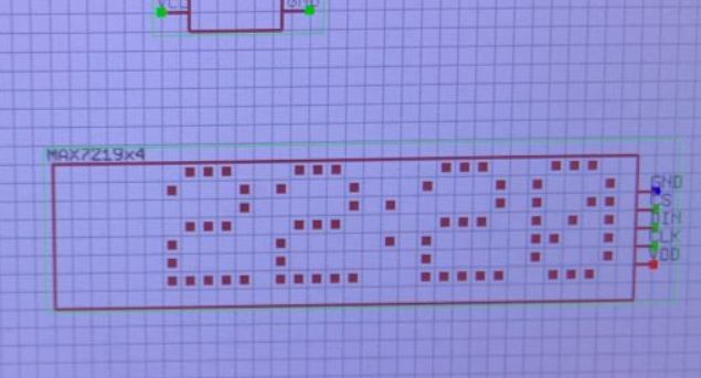
You can also perform operations on pixels. There is a function for this that takes the X Y position and the state of the point:
autoexec = module("autoexec")

def myLogic()
      runCmd("MAX72XX_Scroll 1")
      runCmd("MAX72XX_refresh")
end

runCmd("startDriver MAX72XX")
runCmd("MAX72XX_Setup 10 8 9 4")
runCmd("MAX72XX_Clear 1 1 1")
runCmd("MAX72XX_SetPixel 1 1 1")
runCmd("MAX72XX_SetPixel 1 2 1")
setInterval(myLogic, 100)

return autoexec
The second way:
autoexec = module("autoexec")

var x = 0

def myLogic()
    runCmd("MAX72XX_Clear 1 1 1")

    runCmd("MAX72XX_SetPixel " + str(x) + " 1 1")
    runCmd("MAX72XX_SetPixel " + str(x) + " 2 1")

    runCmd("MAX72XX_refresh")

    x = x + 1
    if x > 31
        x = 0
    end
end

runCmd("startDriver MAX72XX")
runCmd("MAX72XX_Setup 10 8 9 4")
setInterval(myLogic, 100)

return autoexec
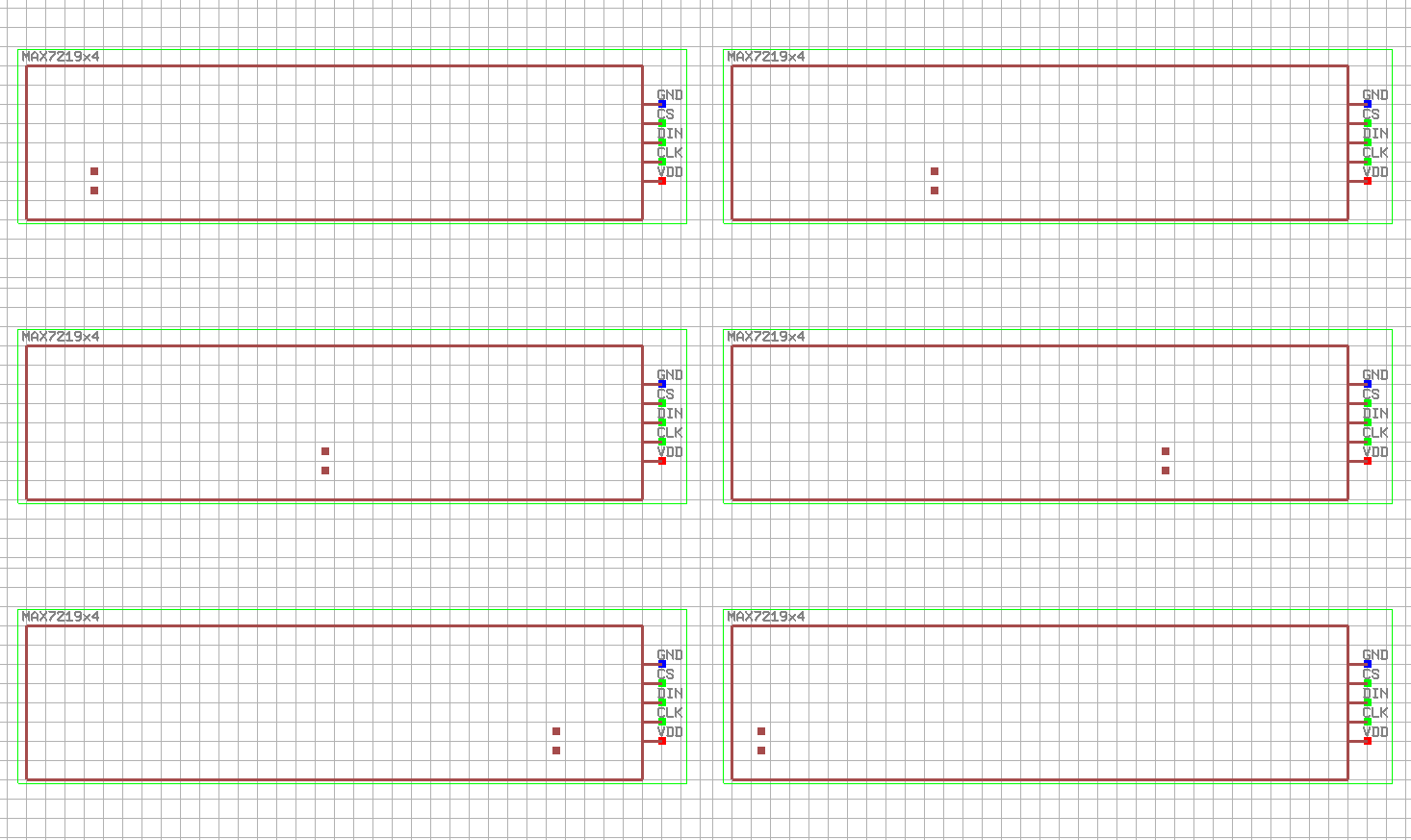
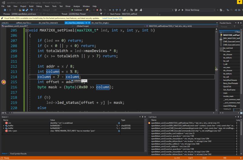
It's also hard not to mention debugging here - complete with variable viewing and even the possibility of changing their values - all conveniently, without the target hardware:
Summary
In the end the choice was for a simpler connection between the virtual MAX7219 and the actual driver code and the SPI communication itself is omitted, but I don't see this as a problem. The operation of the SPI has long since been tested, and it's not something I'm further editing or developing, so I'm not worried about errors there.
The virtual MAX7219 has been linked to the driver at the pixel level, which is fully sufficient for my applications and actually speeds up my prototyping and work.
I have the other drivers such as scripts, NTP, OpenWeatherMap or there Home Assistant integrations already ported to Windows long ago - as well as GPIO and relay handling. The MAX7219 controller was just the last missing piece of the puzzle.
This way, I can essentially do the whole project on the PC (in the Simulator) and then compile it and upload it, for example, to an ESP or BK7231.
Of course, there are some hiccups - certain classes of bugs won't be caught at the Windows stage, such as stack overflows, but I'm fully aware of this and ultimately think it was worth it anyway. I've done a lot of drivers this way already, and I know that these slightly more target platform related bugs are really a small fraction of the work on the way to getting a new feature up and running.
There were some fairly obvious but also important fixes to be made, namely an additional check of the pin connections, as the MAX7219 hanging in the air should of course not display anything, but this was not a priority at this stage.
I will soon show part 2, this will be an improved Simulator. I'll also show the target results after uploading the program to the Wi-Fi module and see if the code takes off, or if I run into problems that only reveal themselves outside the Simulator.
PS: The possibilities are really great - the simulator even already has BL0942 (voltage, current, power measurement) or there DHT11 (temperature and humidity) objects, so there's nothing stopping you from combining them together with such a display.... the scripts can also receive data from the Home Assistant, so I can even display the status of other devices.[/size]


Comments