logo elektroda
logo elektroda
X
logo elektroda

Interior, failure rate and construction of a 50W outdoor LED floodlight with motion sensor

p.kaczmarek2  16 2565 Cool? (+7)
📢 Listen (AI):

TL;DR

  • A destructive teardown examines a 50 W outdoor LED floodlight with a PIR motion sensor that arrived completely inoperable.
  • Inside are a separate PIR module and a separate LED board fed from mains through the motion sensor, fuses, an anti-interference capacitor, and a rectifier bridge.
  • The LED driver uses U1 L1050, SW2N60 N-channel MOSFETs, and 1 MΩ resistors, and the lamp’s phase wire is switched through the PIR sensor.
  • Several LEDs were punctured or faulty, some with black dots still worked, and the author suspects the strings failed sequentially.
Generated by the language model.

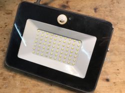
I would like to invite you to a destructive demonstration of a powerful outdoor LED lamp with a PIR motion sensor. The equipment came to me completely inoperable, so I decided to check its construction for teaching purposes. I was mainly puzzled by what was broken, and how the LED control and the motion sensor were implemented.
I don't know the model of this lamp, so the whole thing will be based on guesswork.

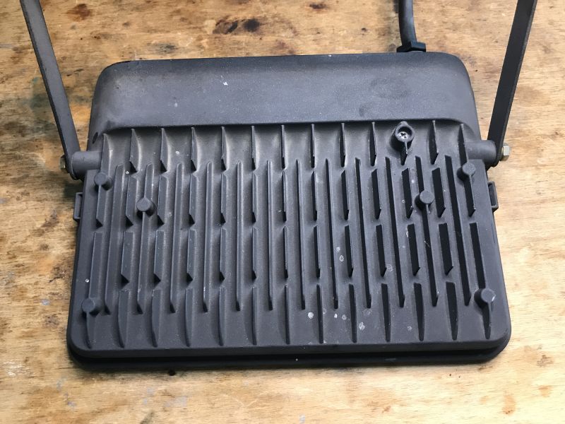
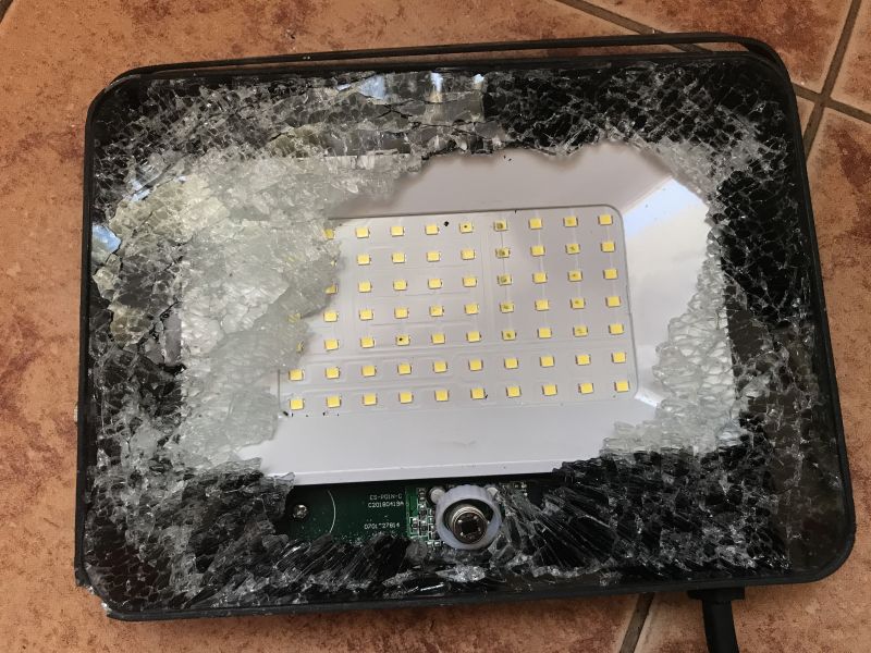
The housing is metal and solid, and you can also see that it has 'fins' on the back for heat dissipation. 50 W in LEDs is a lot of power though, and after all, not all of it turns into light. I wonder what efficiency the LEDs are in there.

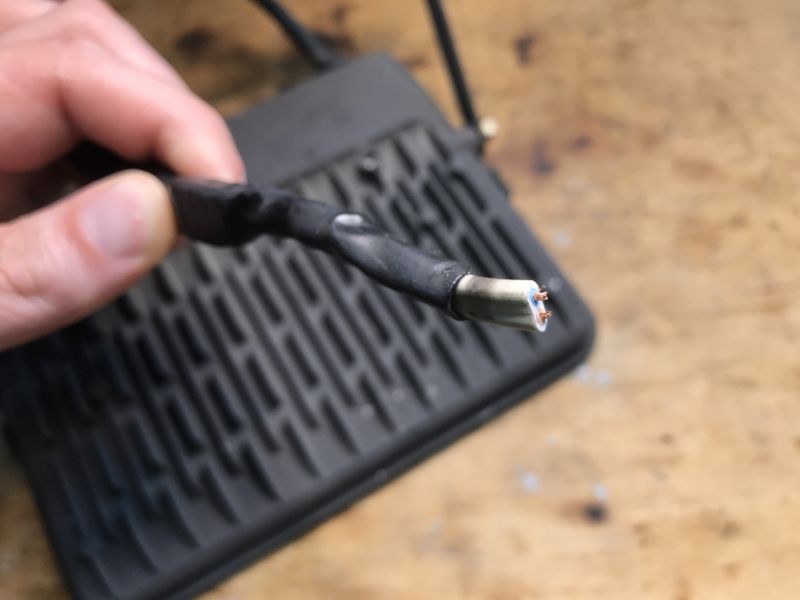
I guess the previous owner decided that earthing was unnecessary and wired the whole thing with a two-wire wire.

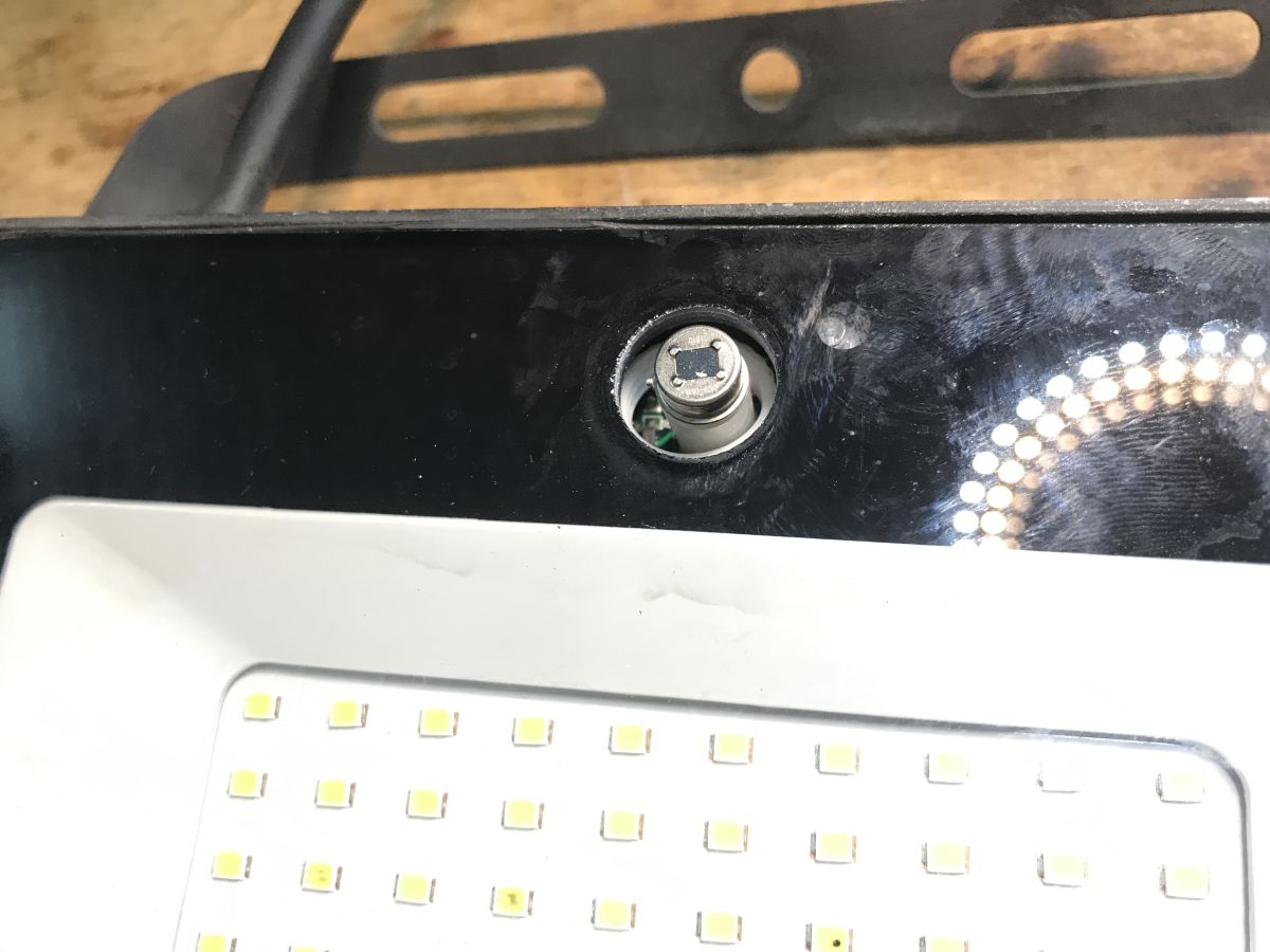
Here you can see a PIR sensor, I associate such from various other hardware, there are also such ready-made modules for Arduino. You can also see the LEDs punctured, this is probably how this hardware ended its life.
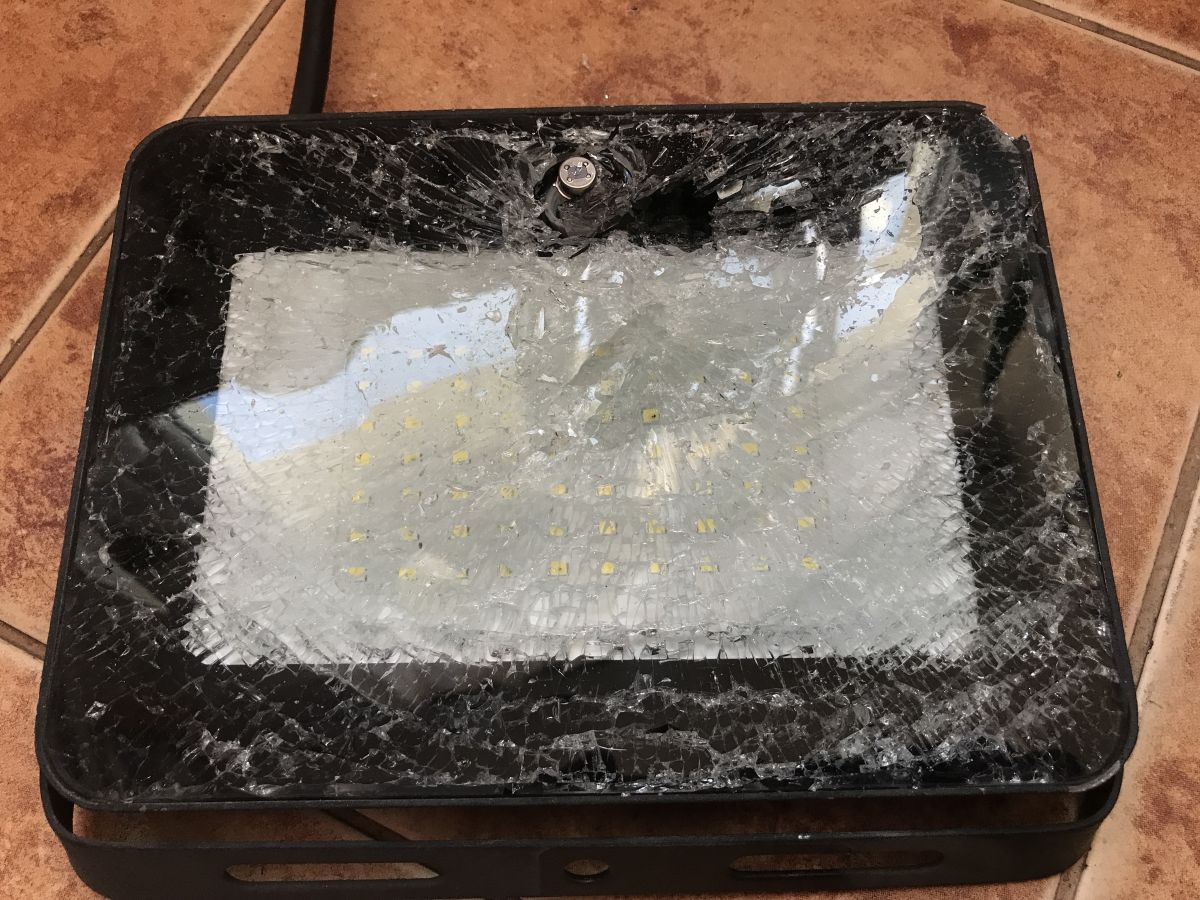
Unfortunately I have not found a way to get inside in a non-destructive way .

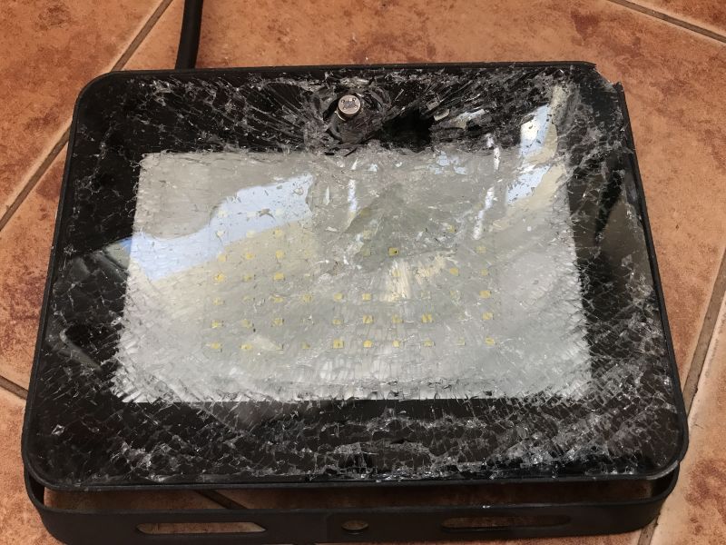
Hammer and drive. Good thing the whole thing is made of special glass that doesn't shoot shards left and right.

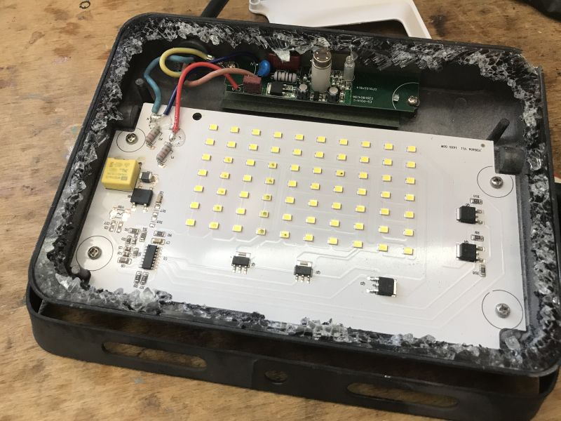
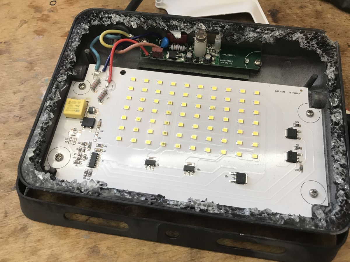
This way we almost have the interior. You can see that there are two separate modules inside. Probably copies without the PIR sensor are also produced. This module with PIR probably works.

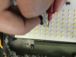
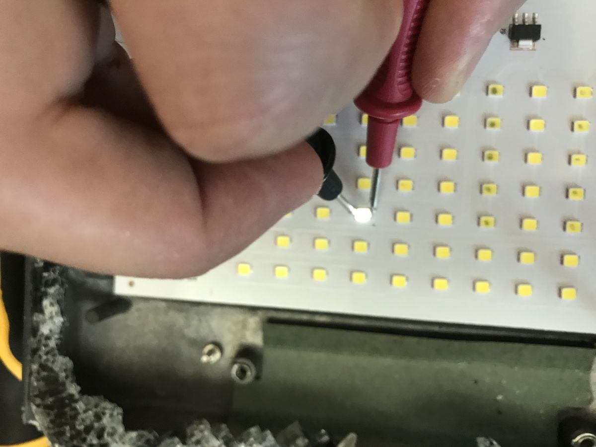
Out of curiosity I tested the LEDs - some are faulty and a break in the circuit. Interestingly, some with black dots still work:

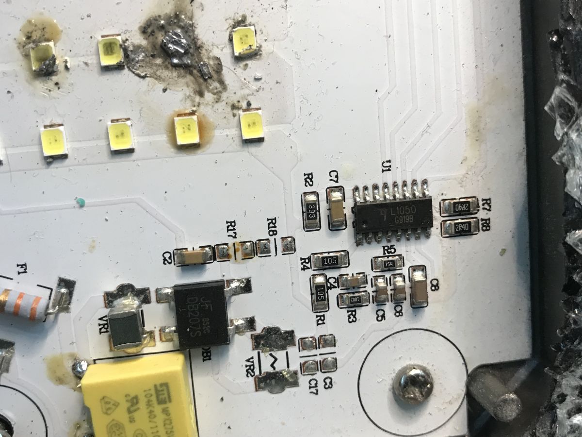
However, let's start at the beginning. There is a phase wire and a neutral wire to the board, with the phase wire connected through the motion sensor. Then we have two fuses, an anti-interference capacitor and a rectifier bridge. Circuit U1 (L1050) appears to be a constant-current LED controller and is powered directly from the mains.

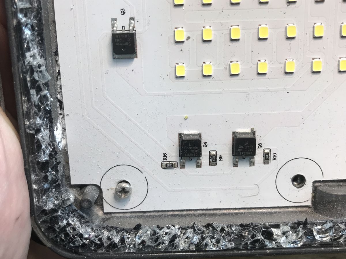
Next we have the transistors, primarily I see the SW2N60 there:

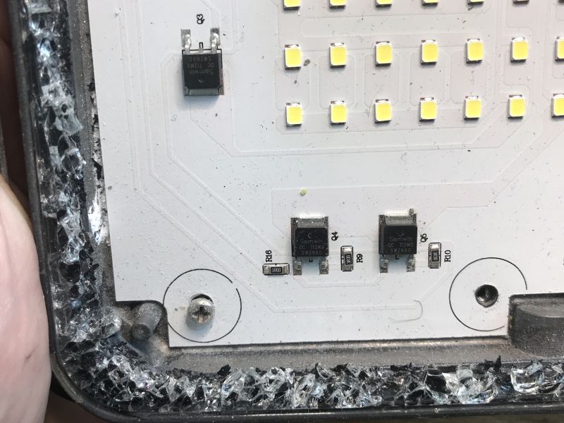
These are MOSFETs with an N-type channel for high voltage, I was surprised by their resistance in the open state:

I managed to find a whole schematic showing a similar circuit:

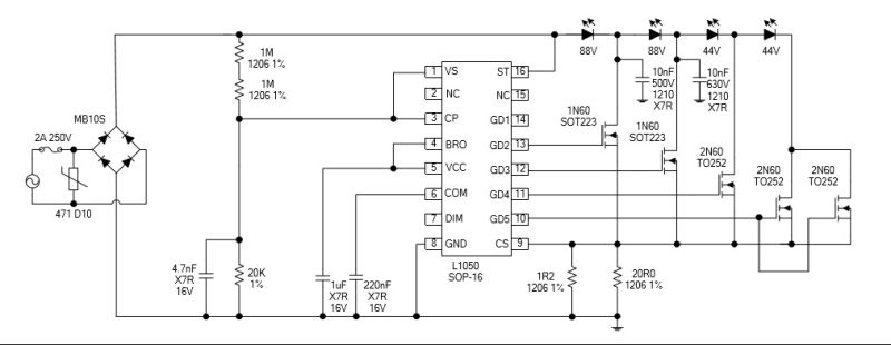
I was quite surprised by the way the LEDs are connected, anyone know what purpose this is used for? The rest is pretty clear, the CS pin is used to measure current (via the voltage drop across the shunt resistor), the 1MΩ resistors to power the controller circuit.
Specification of L1050 LED driver IC showing features and pin diagram in Chinese.

What's left is the PIR module. A cool little gadget. There's even a fuse and a varistor.
Electronic PIR motion sensor board held in a hand Electronic module with PIR sensor held in hand, visible capacitors and resistors Bottom side of a PCB with visible traces and solder points, held above a wood surface

The lamp is potentially repairable but it is now without glass and in addition soldering in new LEDs is difficult, the whole thing effectively dissipates heat. A heater would be useful.

In summary , this was more of a one-off. There was a separate PIR module and a separate LED board with a constant current controller supporting several strings. Looking at the damage to the LEDs I get the impression that the strings were failing sequentially, although given the attached diagram I have my doubts as to why this is (if it is) wired this way, perhaps someone else can explain.
Do you use these types of LED lights, how do you find their failure rate and longevity?

About Author
p.kaczmarek2
p.kaczmarek2 wrote 14439 posts with rating 12405 , helped 650 times. Been with us since 2014 year.

Comments

fachman1964 06 Jan 2026 12:03

I don't know if they are all glued with the same black glue, but I've dealt with some that, when the metal part was heated at the contact with the glass, the glue mass became flexible. I lifted the glass... [Read more]

androot 06 Jan 2026 12:28

The LEDs are supplied with full, rectified, pulsating mains voltage. To minimise flicker, when the voltage is lower than the conduction voltage, a piece of the section is cut off. Will work well with a... [Read more]

fachman1964 06 Jan 2026 16:27

What results, the black "ooze" could be cut out? [Read more]

szeryf3 06 Jan 2026 18:10

Even if you were to replace with new LEDs, it is a matter of a short time when the new LEDs will dislodge the old ones. This is why these and similar lamps are disposable. [Read more]

Dydelmax 06 Jan 2026 18:42

I have repaired several similar headlights for myself that were written off, except that they do not have a motion sensor. You can get the glass out in its entirety with a bit of self-denial using GSM... [Read more]

sampler 07 Jan 2026 08:58

I have repaired quite a few such lamps. Usually the cause is low quality diodes, so the repair is also for a while. Firstly, the method of opening. There is a simple method. Drill a small hole fi 2-3 mm... [Read more]

p.kaczmarek2 07 Jan 2026 09:16

And has anyone tried reducing the controller's current setting so that the LEDs glow a little dimmer but live longer? [Read more]

klamocik 07 Jan 2026 10:37

Isn't it sometimes the case that the lamp starts to glow from around 100 volts? [Read more]

Kajox 07 Jan 2026 16:09

For me, the worst floodlights because of the blinking during operation. Not everyone notices this. You can see it perfectly when trying to record a video or take a photo with your phone. Typical importer... [Read more]

leo5114 07 Jan 2026 18:39

These illuminators are useless, total rubbish. [Read more]

szeryf3 08 Jan 2026 08:13

That's why I use what I call "mixed light" when using this type of lamp at the workbench. [Read more]

fachman1964 10 Jan 2026 17:49

I only buy these for myself. 1. Bolted on, no glue, only gaskets. 2. LED COB 36 V also bolted to the heat sink with thermally conductive paste, zero glue. Repair is a pleasure. Although none have damaged... [Read more]

żarówka rtęciowa 11 Jan 2026 12:55

Welcome. I have such a spotlight acquired from a junkyard mounted in a work lamp on a tripod. I replaced the LED with a higher wattage one and used an external Osram power supply. [Read more]

partyzancik 17 Jan 2026 20:45

And why complicate things? Isn't it better to improve the heat dissipation with the existing power? You need to unscrew the diode board and level the surface to which the board is screwed and give better... [Read more]

partyzancik 18 Jan 2026 11:13

I occasionally buy scrap for the parts themselves and let me just say that the new COBs are a failure. The old ones had copper PCBs and the new ones have aluminium PCBs. The housings are also so-so and... [Read more]

LEDówki 27 Feb 2026 06:54

And what do you illuminate with it? If I have a torch, is it an illuminator or a hand-held illuminator? Is it worth repeating stupid names invented by stupid people for stupid people? A disposable lamp... [Read more]

FAQ

TL;DR: A torn‑down 50 W outdoor LED floodlight showed failed LED strings and a separate PIR module; “this was more of a one‑off.” [Elektroda, p.kaczmarek2, post #21800292]

Why it matters: If your motion‑sensor floodlight dies, this FAQ shows how to diagnose driver, LED, and PIR faults safely and quickly—for DIYers and repair techs solving no‑light or flicker issues.

Quick Facts

What actually failed in the 50 W PIR floodlight?

Multiple LEDs in the array went open‑circuit, leading to string outages. Evidence suggested strings failed sequentially, causing total loss of light. The PIR module appeared intact. The metal housing and tempered glass survived the teardown, but opening required destructive methods. [Elektroda, p.kaczmarek2, post #21800292]

How is the motion sensor wired inside these lights?

Live (phase) enters the PIR module first and exits to the LED driver board. Neutral goes directly to the driver. This lets the PIR switch mains to the constant‑current driver whenever motion is detected. It keeps sensing and power paths simple and serviceable. [Elektroda, p.kaczmarek2, post #21800292]

What does the L1050 constant‑current controller do?

The L1050 regulates LED current from rectified mains. It measures voltage across a shunt at the CS pin to keep current stable. Start‑up is provided by high‑value resistors feeding the IC. Stable current helps prevent thermal runaway and flicker. [Elektroda, p.kaczmarek2, post #21800292]

Why use several LED strings instead of one long string?

Multiple strings spread voltage and heat, and allow current sharing under the driver’s control. The teardown schematic showed several controlled strings, improving reliability and optical uniformity. However, one open LED can drop an entire string offline. [Elektroda, p.kaczmarek2, post #21800292]

What’s the role of the SW2N60 MOSFETs in this driver?

SW2N60 N‑channel MOSFETs handle high‑voltage switching in the primary regulation stage. They work with the controller to chop rectified mains and set LED current. The author noted their on‑state resistance as a notable characteristic in this build. [Elektroda, p.kaczmarek2, post #21800292]

How does the CS (current‑sense) pin protect the LEDs?

A low‑value shunt resistor develops a small voltage proportional to LED current. The controller reads this at CS and limits drive when the threshold is reached. This safeguards the array during surges and stabilizes brightness. [Elektroda, p.kaczmarek2, post #21800292]

What quick checks confirm a bad LED string?

Test each LED with a bench supply or diode tester. Open LEDs won’t pass current; some black‑spotted dies may still glow faintly. Also inspect for cracked solder on the MCPCB. “A heater would be useful” for rework due to heavy heat‑sinking. [Elektroda, p.kaczmarek2, post #21800292]

Is repair realistic without replacing the entire array?

Yes, but it’s laborious. Replacing failed LEDs on the metal‑core board needs strong preheat and careful reflow. Access can be destructive because the front glass is sealed. Budget time for resealing against moisture ingress after repairs. [Elektroda, p.kaczmarek2, post #21800292]

Why is earthing essential on a metal floodlight?

The sample unit was wired two‑wire without earth. A missing protective earth risks exposed metal becoming live during faults. Always connect earth on Class I housings to meet safety expectations and reduce shock risk. [Elektroda, p.kaczmarek2, post #21800292]

What does the PIR sensor board include besides the detector?

It includes its own fuse and a varistor for surge suppression, plus the control electronics that gate mains to the driver. That protection reduces nuisance failures from spikes and improves sensor longevity. [Elektroda, p.kaczmarek2, post #21800292]

Why were 1 MΩ resistors used in the driver?

High‑value resistors provide a tiny start‑up current to power the controller from rectified mains. The board used 1 MΩ parts to bias the IC before switching takes over. This is typical in non‑isolated constant‑current LED drivers. [Elektroda, p.kaczmarek2, post #21800292]

Can I open a sealed LED floodlight without breaking the glass?

In this case, no. The author could not find a non‑destructive entry method, then used force to access the internals. Tempered glass minimized dangerous shards, but the lens was sacrificed. Plan for resealing or lens replacement. [Elektroda, p.kaczmarek2, post #21800292]

How do I diagnose a dead PIR floodlight in 3 steps?

  1. Verify mains, earth, and PIR output live to the driver.
  2. Check fuses, bridge, and CS shunt continuity on the driver board.
  3. Test LED strings for opens; replace failed dies and reseal the housing. [Elektroda, p.kaczmarek2, post #21800292]

Do non‑PIR versions share the same LED board?

Yes, that’s common. The teardown showed separate boards, implying a shared LED/driver assembly with or without the PIR module. This lowers manufacturing cost and simplifies variants. [Elektroda, p.kaczmarek2, post #21800292]

What edge cases should I expect after repair?

If one string is weaker, sequential failures can recur. Moisture ingress after resealing can corrode contacts. Always reflow evenly, replace gaskets, and test at full load before mounting outdoors. [Elektroda, p.kaczmarek2, post #21800292]

Which onboard protections help these lights survive surges?

Dual fuses, an EMI capacitor, and a varistor on the PIR board provide basic protection. Proper current sensing and controlled startup further protect the LED array during transients. [Elektroda, p.kaczmarek2, post #21800292]
Generated by the language model.
%}