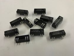
Today a little tidbit I came across while developing one of my projects. I was looking for a simple way to mechanically disconnect microcontroller/ESP controlled lines, with a minimum of additional components. This is how I came across the very small V23100-V4 dual signal relays. Interestingly, the manufacturer explicitly emphasises in the documentation that the coil can be controlled directly by TTL signals, which is immediately appealing for projects with microcontrollers.
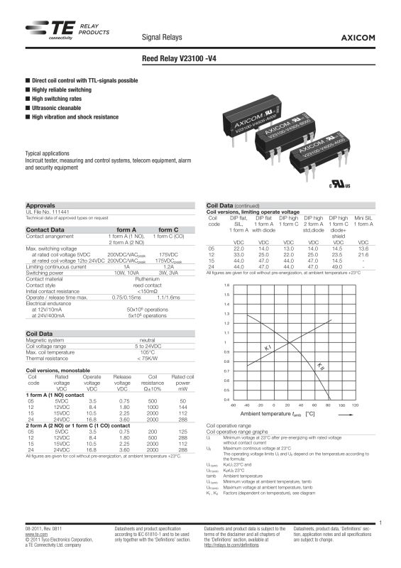
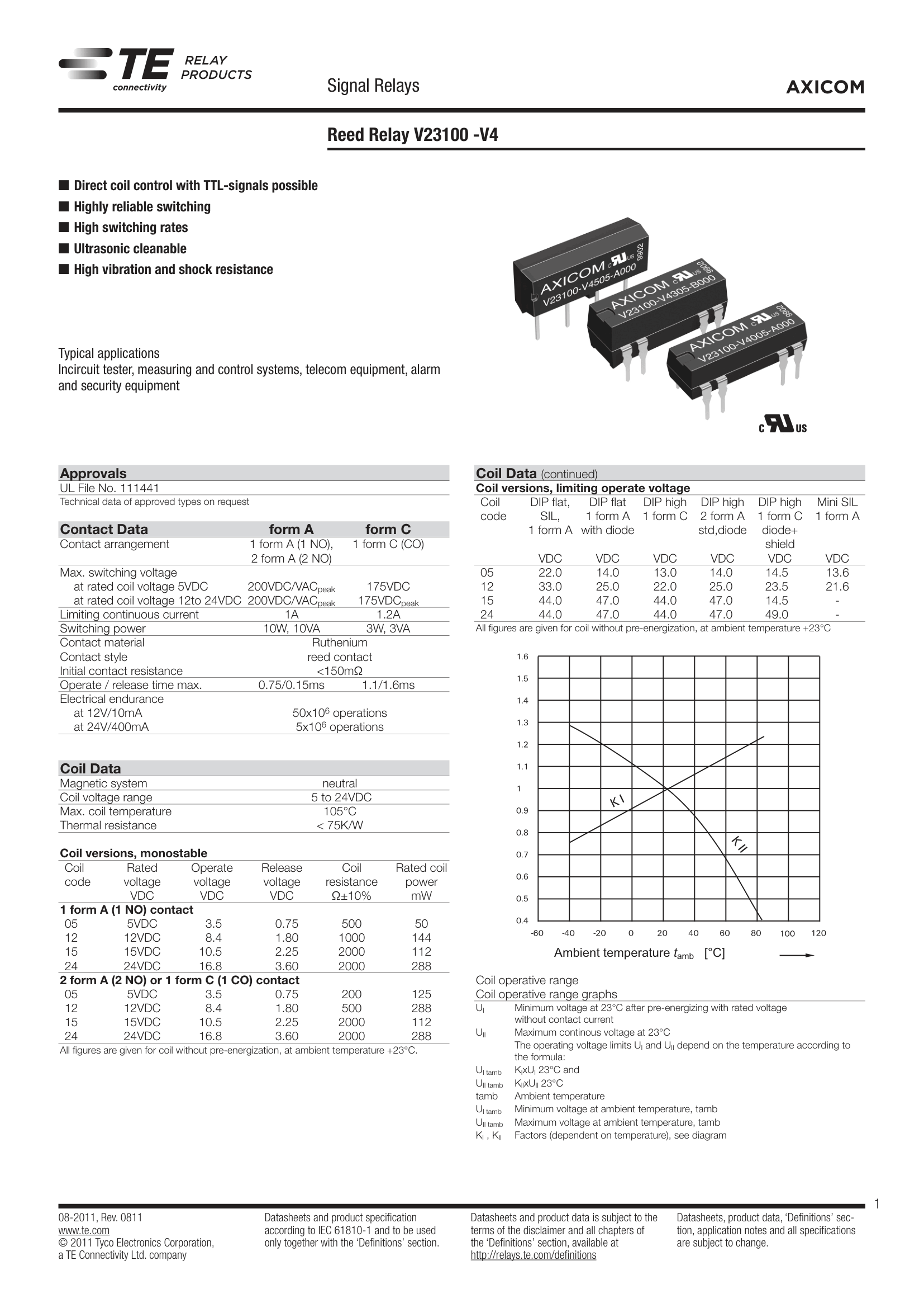
Consider the parameters from the datasheet:
- maximum contact current: up to 1 A
- maximum voltage: up to 200 V
- maximum switching power: 10 W
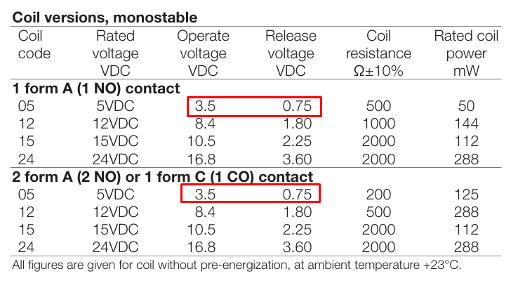
For such a small relay, these are quite reasonable values - especially when it comes to signal applications or small loads. The coil parameters are also interesting:
- coil resistance: ~500 Ω
- coil power: ~50 mW
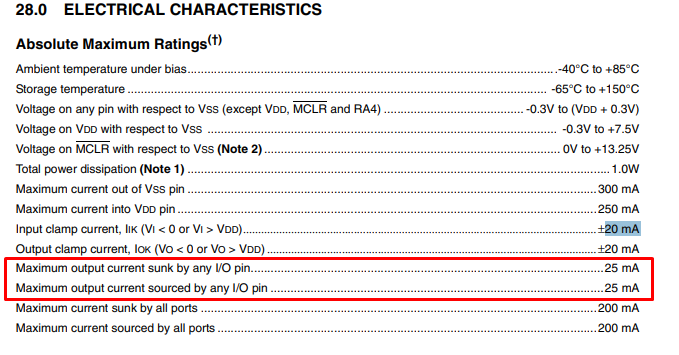
This means that the control current is very low, which is precisely what makes direct control from the microcontroller output possible (at least in many cases). In practice, it is important to check how much current can be drawn from the GPIO. For example, for the PIC18F2550 it is 25 mA:
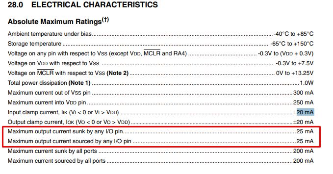
Assuming a supply voltage of 5 V, about 10 mA will flow through the ~500 Ω coil. Well under the limit. Just what about lower voltages? According to the datasheet note:
- closing voltage (operate): 3.5 V
- opening voltage (release): 0.75 V
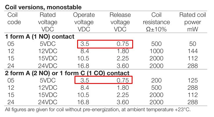
These values suggest that the relay is designed with low-voltage logic in mind. However, an interesting question arises: in practice, will it also work at even lower voltages than the declared 3.5 V? There is often some design reserve in such components, so I thought I would give it a go with ESP. DIY projects have their own rules, it's not mass production, so you can afford to do more. So it's time for testing.
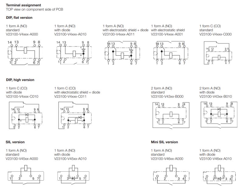
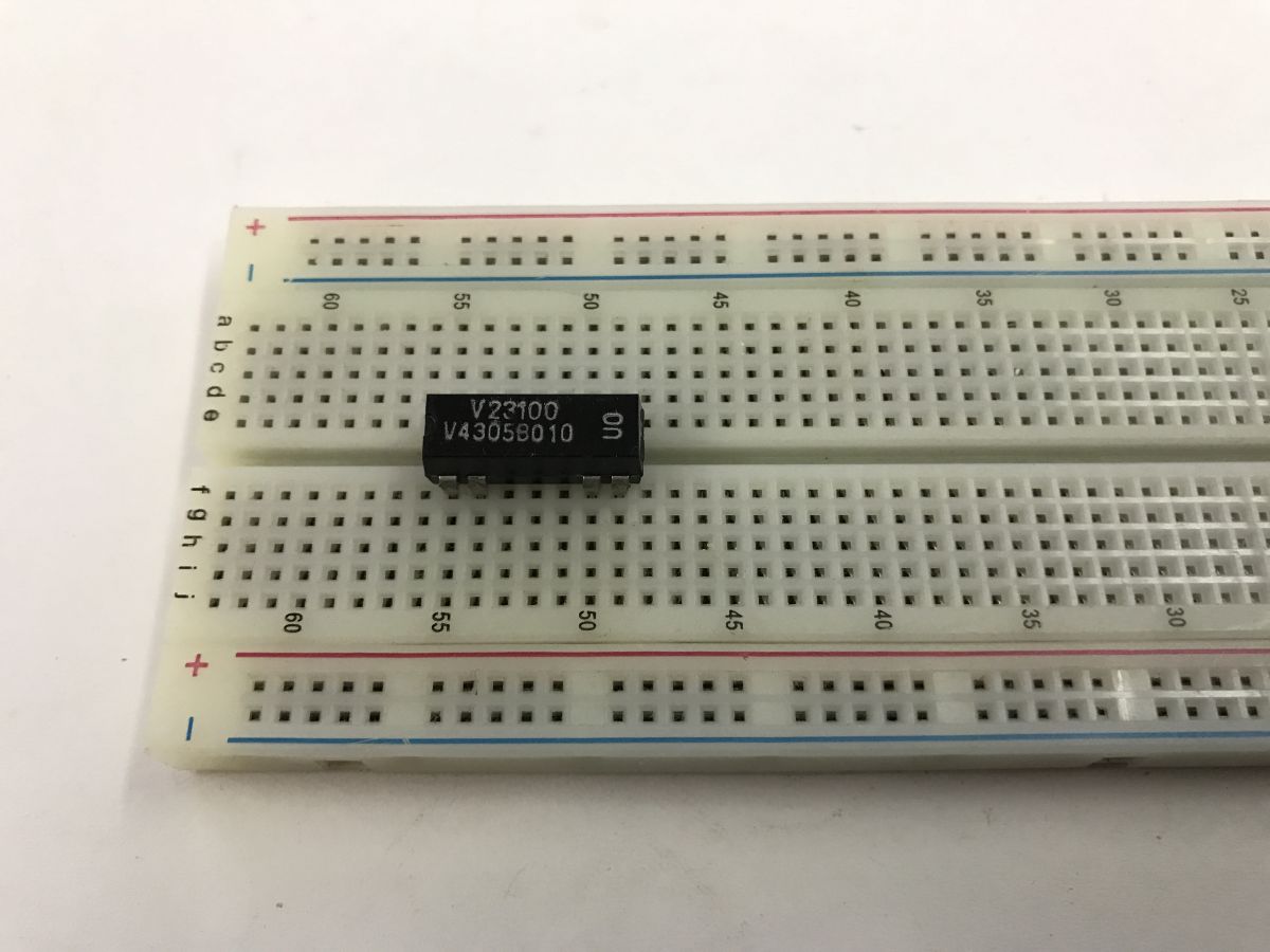
The whole thing has a standard DIP raster, so it fits on a contact board:

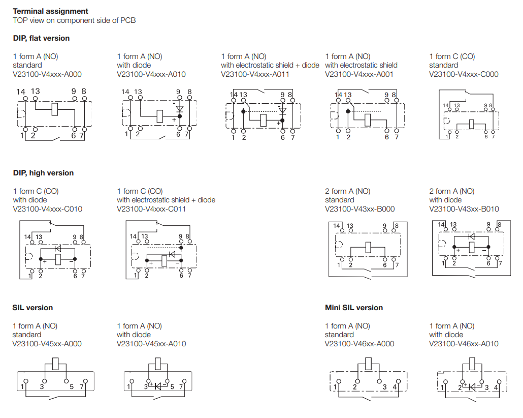
Leads - yes, there is already a protection diode inside in parallel to the coil, so you can't connect the coil in reverse either:
First test at 5 V - no surprise here rather, the whole thing works.
Second test - controlled from ESP32 at 3.3 V:

Here I've stretched the specification a bit, as the manufacturer announces the contacts close from 3.5 V rather than 3.3 V, but nevertheless the relay works too.
In summary , this was an example of a small relay that in practice turns out to be much more 'friendly' to microcontrollers than the datasheet note alone might suggest. Thanks to the very low coil power consumption, it can in many cases be controlled directly from the GPIO, without an additional transistor. Of course, in production applications it is better to stick to the manufacturer's specifications, but in DIY projects such a reserve of parameters can be very useful.
Undoubtedly this was a rather beginner's topic, but I hope it may have interested someone.
Have you used this type of relay in projects, and if so, for what? 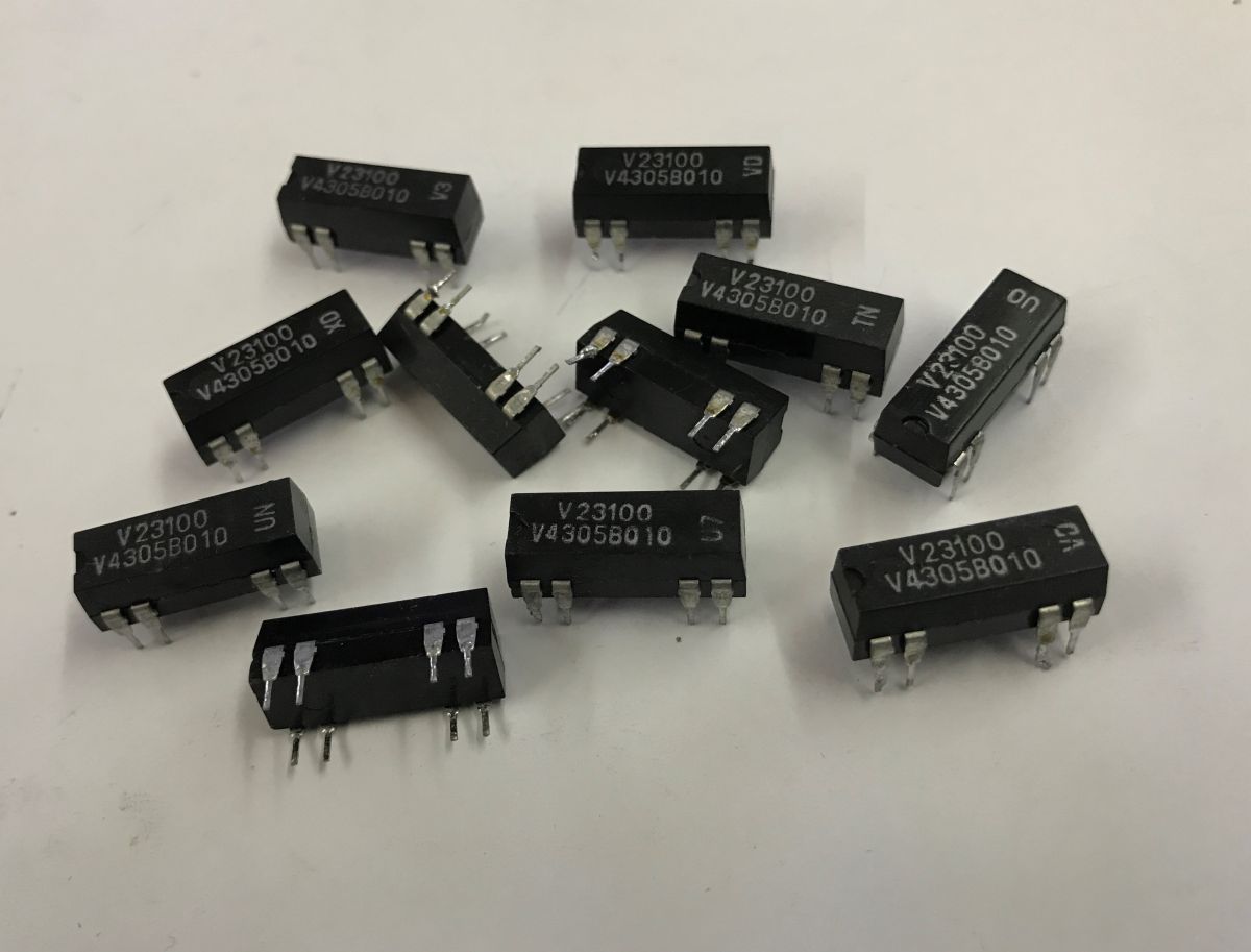

Comments
The question is whether one is making something for art, for the desk. In such circumstances, one gets away with a great deal. For a product, especially one exposed to non-room temperatures, I would not... [Read more]
Right, but as I wrote in the next sentence - in production you should stick to these parameters and preferably with a margin, especially because if something goes wrong, a discrepancy of parameters on... [Read more]
This makes sense... The 5 V relay is often the only receiver on 5 V so it makes the design more expensive and larger. And that it devours a lot of current is less of a problem than a separate power supply.... [Read more]
In the IoT devices I have tested, I am unlikely to have seen opto-isolation in such an application, and we have shown a bit of these devices on the forum. Here's a dedicated search engine (each result... [Read more]
Where exactly did he write about this? TTL levels are ranges from 0 to 0.8 V for the low state and 2.4 to 5 V for the high state. In the table with the DS of this relay, there is a range from 3.5 V so... [Read more]
I was referring to this passage from the catalogue note: https://obrazki.elektroda.pl/7812401500_1776768079_bigthumb.jpg [Read more]
It is possible to control this way but this approach has some limitations. Firstly, you have to be careful with the sum of the input currents relative to the supply (ground or power) pin. Controlling... [Read more]
You can disconnect the relay for the duration of the measurement, the shortest time in the relay DS is 0.15 ms. [Read more]
Will it drop from 10 bit to 9 bit? Not likely, as the problems could be with the accuracy of the ADC or rather with the reference voltage, as there will be offsets due to currents flowing in the ground... [Read more]
What is this project? Who is the author? Where have you seen it? Motivations can always be sensibly explained, either a technical reason or someone's whim. [Read more]
My question is, what is the guaranteed number of switches. ? [Read more]
These are hermetic reed switches so they safely last for millions. [Read more]
https://obrazki.elektroda.pl/8945003400_1776788643_thumb.jpg [Read more]
https://www.elektroda.pl/rtvforum/topic4144485.html [Read more]
Separating the ground (and not just the power supply) of the control part from the executive part can be convenient, e.g. with many such modules, thanks to opto-isolation, the connection point for these... [Read more]
In the diagram you have the answer - the grounds are separate, they can be combined and separated, the relays can be fed from one power supply and the ESP from another. You will see what happens between... [Read more]
No... Everything flies from the power supply to J1, then there's 5V from it linear to 3V3 to the ESP. From 5V a small isolated inverter is used to make Relay-5V. The common ground of the relays and ESP....... [Read more]
Control current is one thing, but I assume that a suppression diode must also be inserted in parallel to the relay coil. Will it be sufficient to protect the after all quite sensitive to overvoltage output... [Read more]
Have you looked at the internal schematics of the relays the Author has provided? Half of these circuits (relays) have an integrated diode. [Read more]