I invite you to a practical test of the new image generator from OpenAI. In this topic I will test the performance of GPT-Image 2 on various electronics related tasks, there will be drawing schematics, describing devices and also editing photos and graphics. In addition, I will compare the whole thing with the Nano Banana 2. Is the new model really better? Let's find out!
A large part of the prompts and tasks in this topic have already been tested with the Nano Banana models, feel free to visit the related topic:
Will the Nano Banana generate an electronic diagram or infographic? Comparison of the two models
Here I have re-made them - I used the free
LMArena and the two models available there:
- gpt-image-2 (medium)
- gemini-3.1-flash-image-preview (nano-banana-2) [web-search]
Please note that depending on the models available to you, the results may vary.
Presentation format
First the prompt will be given, then (if available) the photo attached for AI. Then the model name will be given, the images generated by it, then another model name and again the images. Finally, my loose comments.
Model comparison
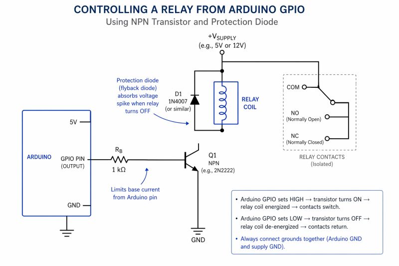
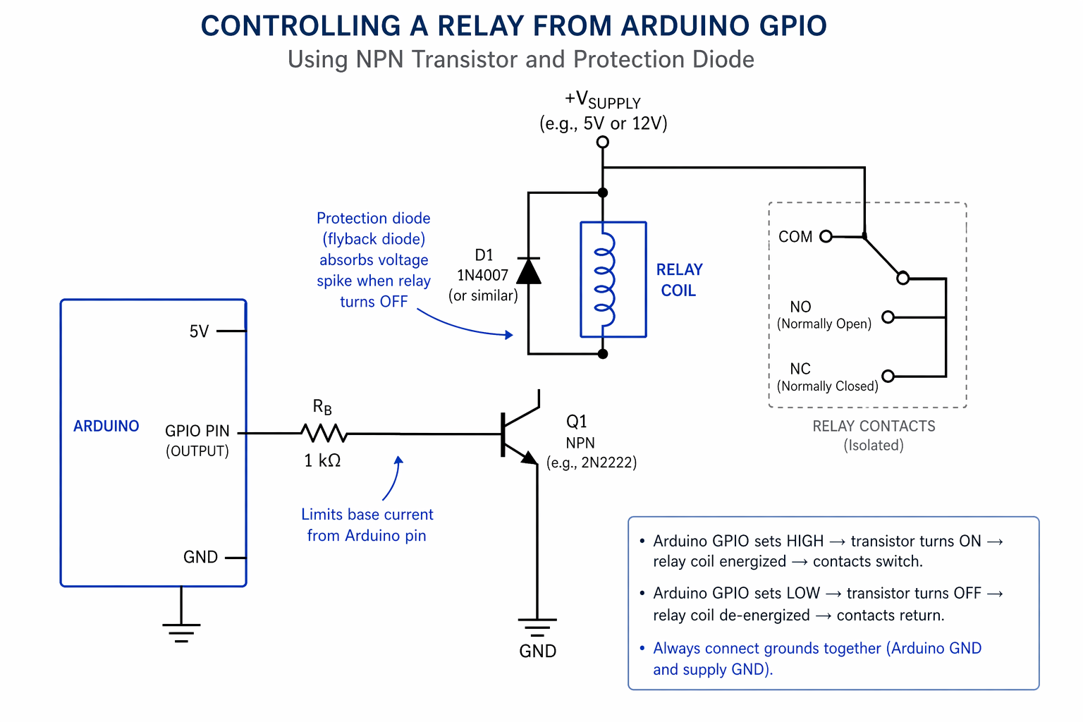
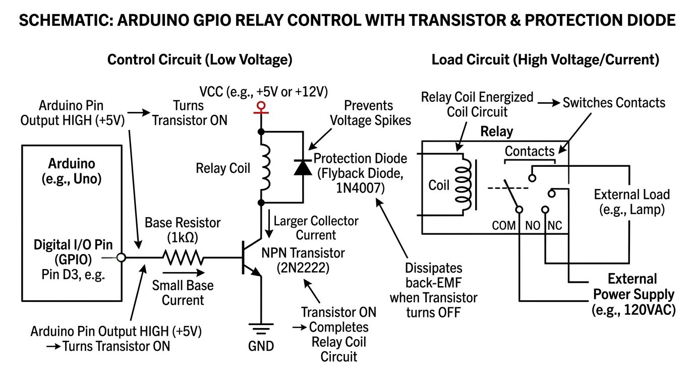
a schematic showing how to control relay from arduino GPIO with a transistor and protection diode
gpt-image-2 (medium)
gemini-3.1-flash-image-preview (nano-banana-2) [web-search]

It is immediately apparent that GPT-Image 2 has a distinctive style, especially these annotations and explanations, worse that they are not correct. The relay connection to the manifold is lost....
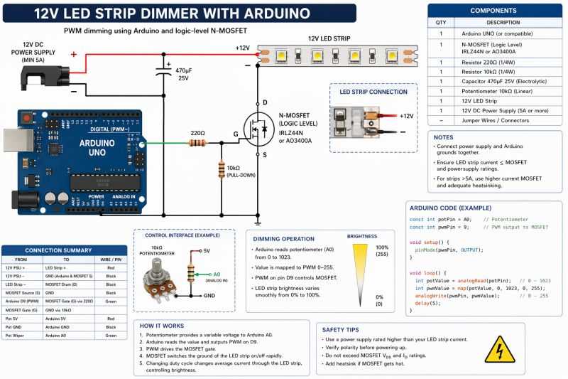
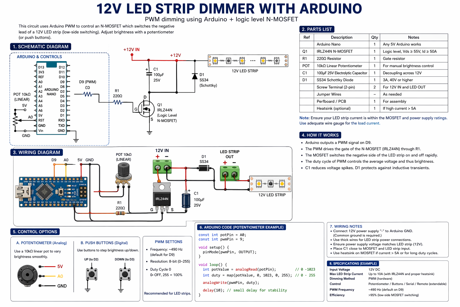
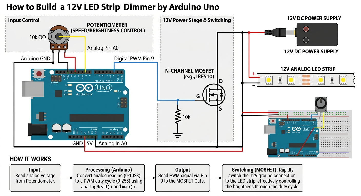
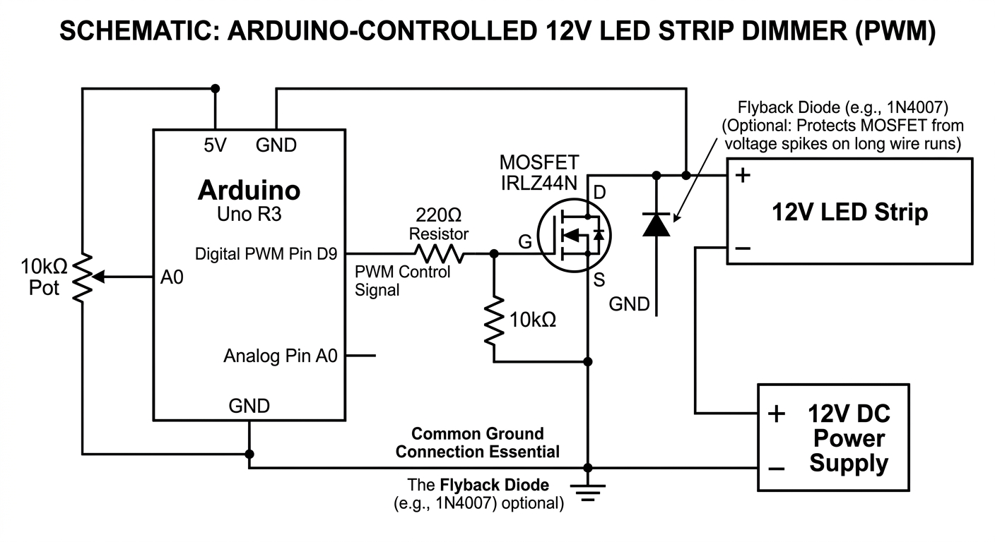
draw detailed schematic showing how to make a 12V LED STRIP DIMMER with Arduino
gpt-image-2 (medium)

gemini-3.1-flash-image-preview (nano-banana-2) [web-search]
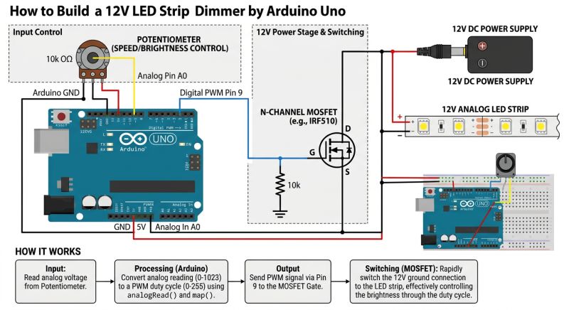
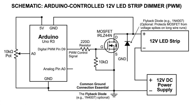
GPT-Image 2 generates more complex images, puts a lot of explanations, diagrams, tables on them, but with the logic is still a bit worse. Still that shorting of the 12 V line with the drain of the MOSFET transistor.... interesting that the PARTS LIST however agrees with the schematic. Why does D9 (pin?) have a resistor schematic? What is the Schottky diode there for? The code is even there... and came out quite good? Information about the common ground also correct.
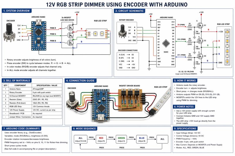
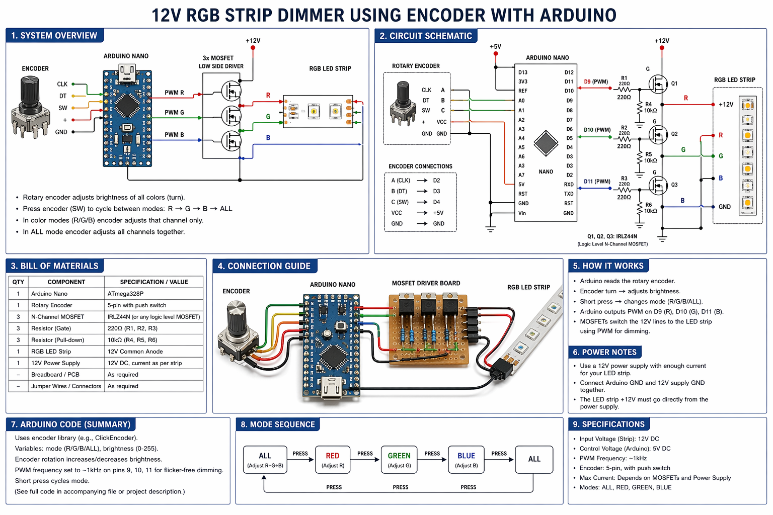
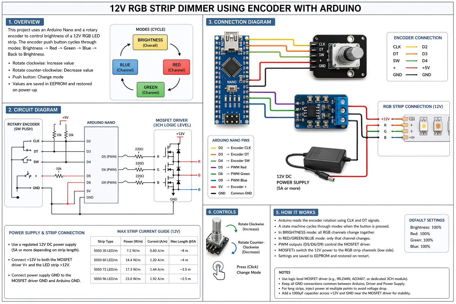
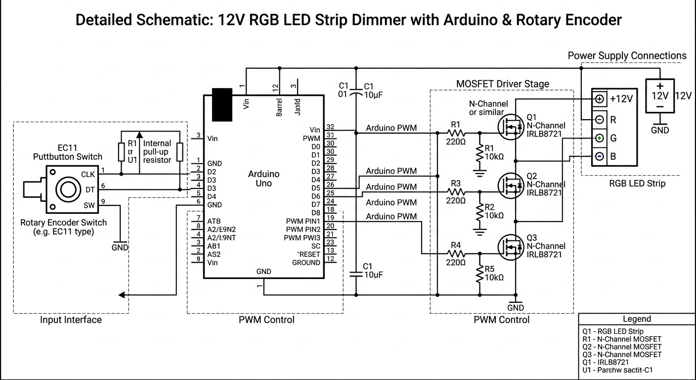
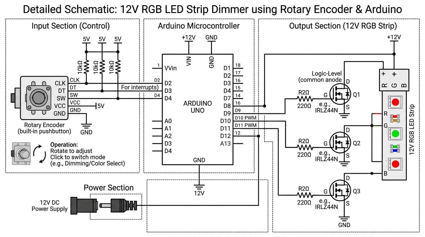
draw detailed schematic showing how to make a 12V RGB STRIP DIMMER using encoder with Arduino
gpt-image-2 (medium)
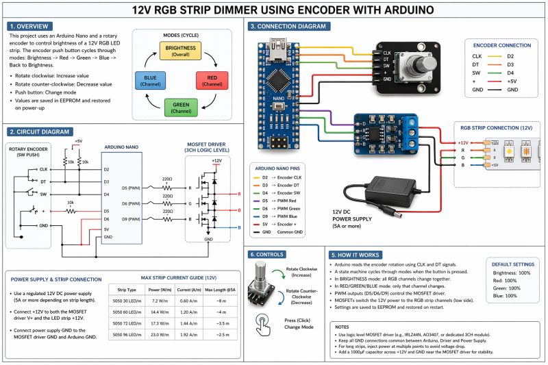
gemini-3.1-flash-image-preview (nano-banana-2) [web-search]
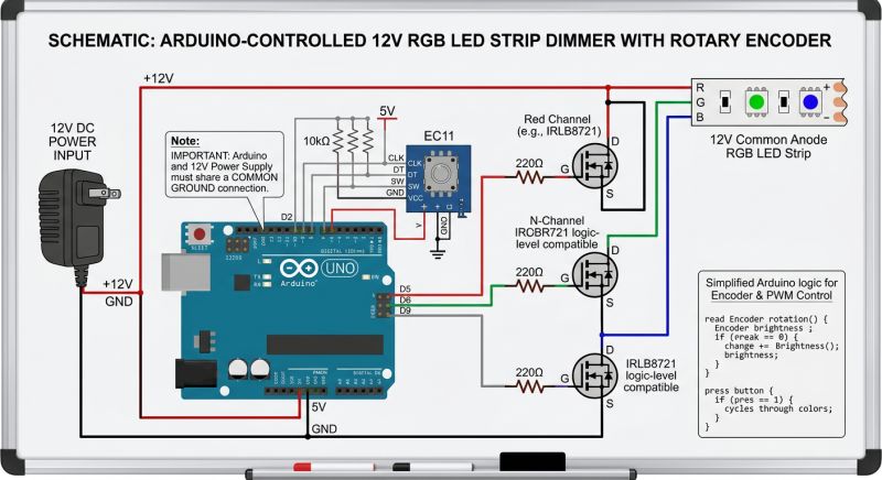

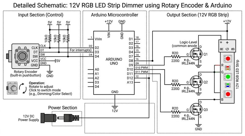
As before - GPT-Image 2 likes to do complex graphics, but with logic it's worse. Still, those MOSFETs cascade....
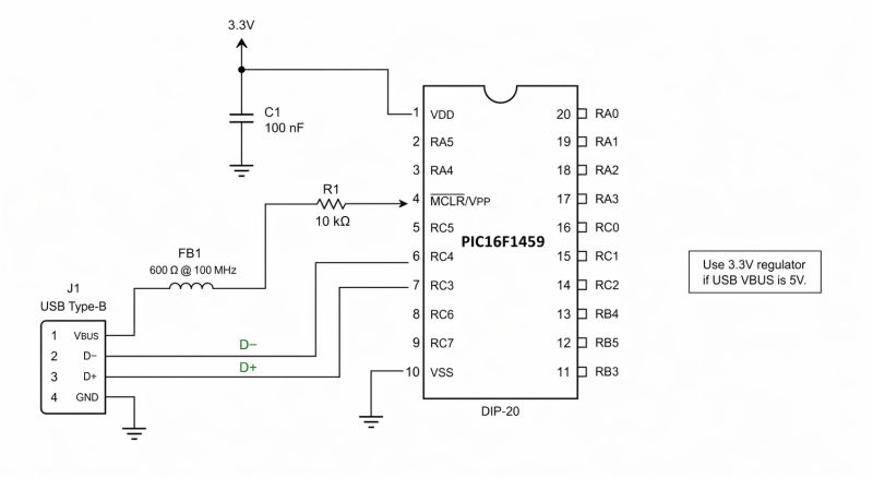
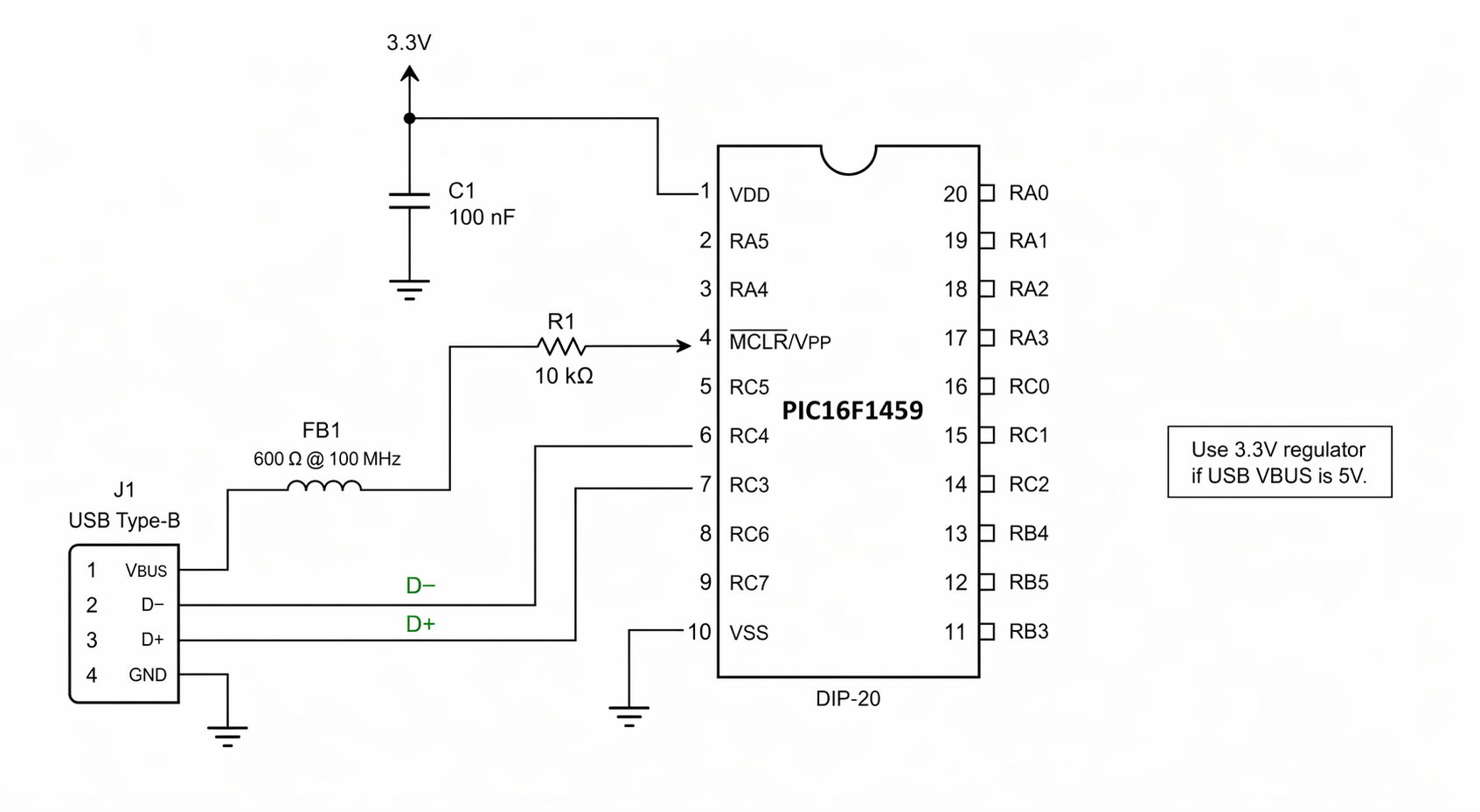
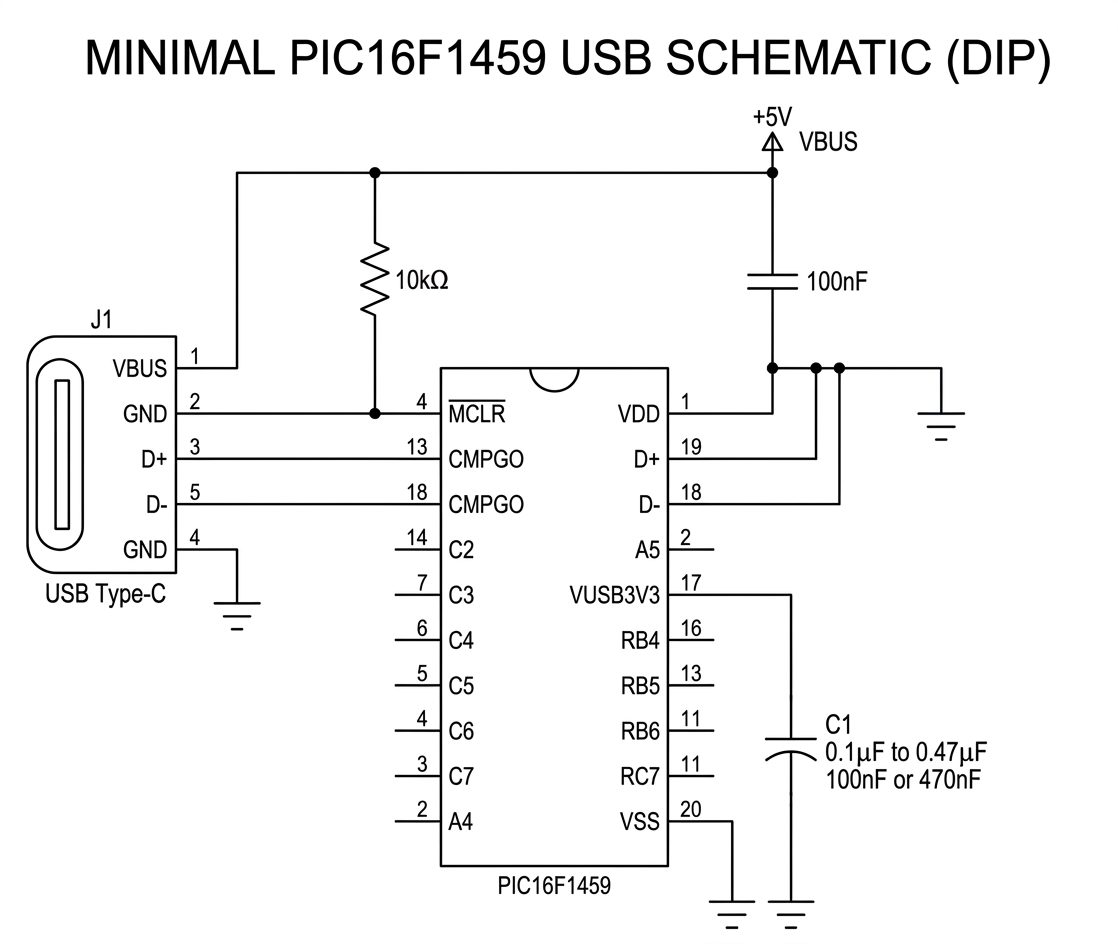
show minimal connections of PIC16F1459 in DIP package schematic with USB connector
gpt-image-2 (medium)
gemini-3.1-flash-image-preview (nano-banana-2) [web-search]

Pinout gets a bit mixed up with the actual one. Pin 10 is actually RB7 and 11 is RB6. USB is on 19 and 18. still those VBUS to MCLR.... but the Nano Banana did worse anyway, although .... D+ and D- tracked well.
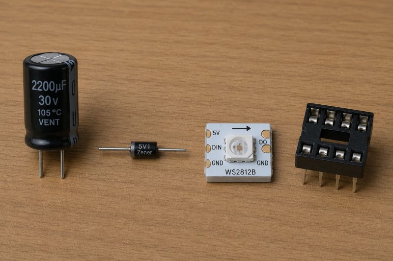
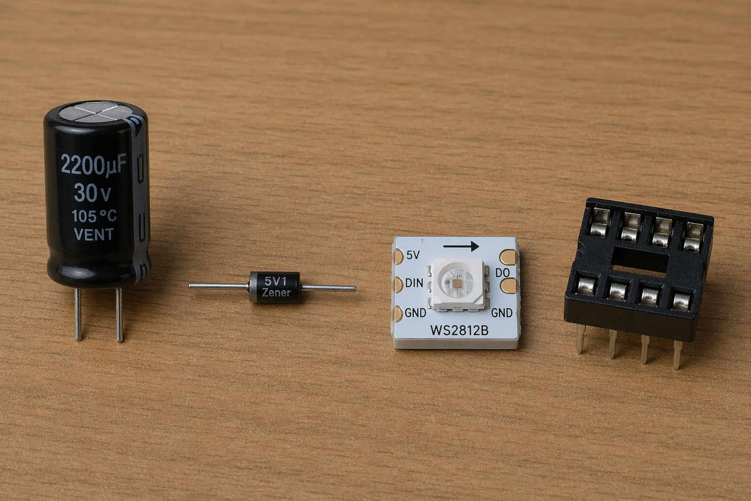
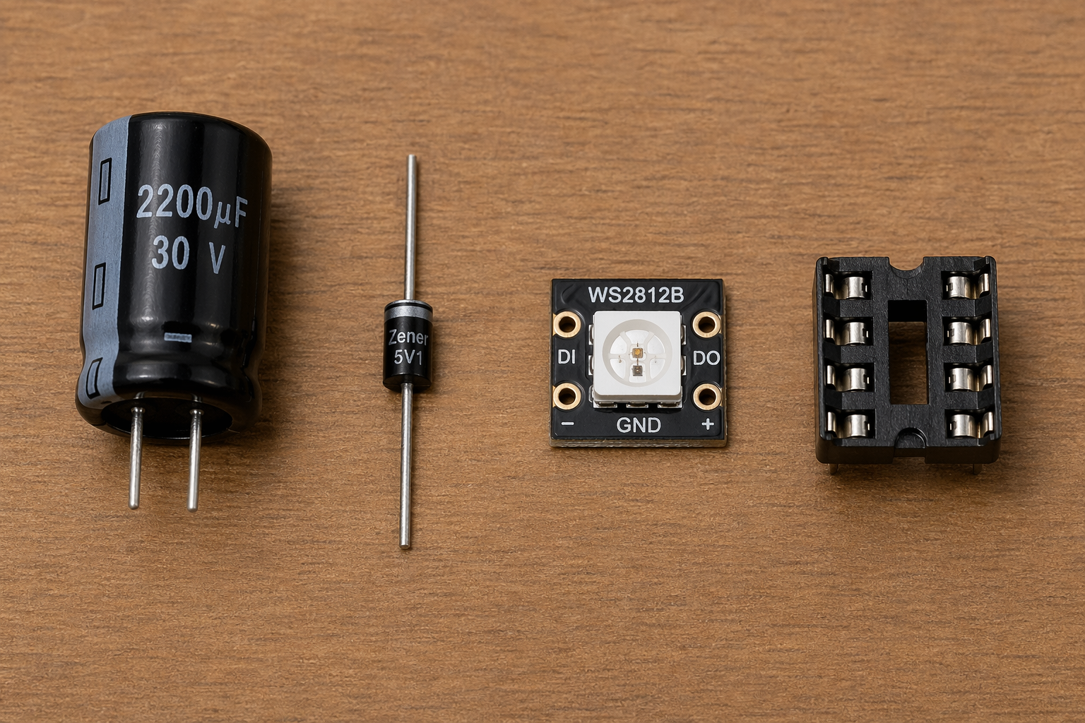
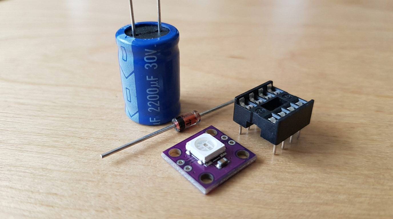
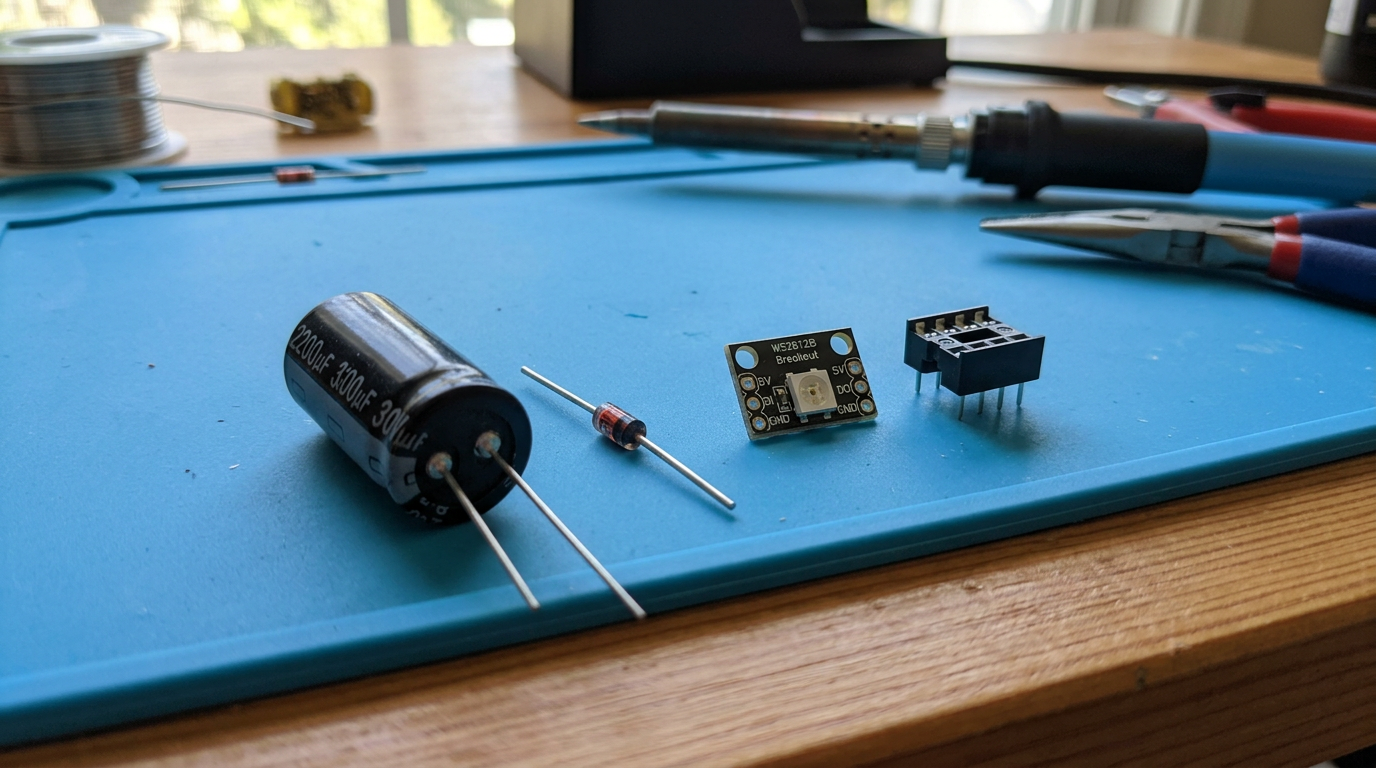
Draw four elements on table: a 2200uF 30V capacitor, a Zener diode, a WS2812B single module, and a DIP8 socket
gpt-image-2 (medium)
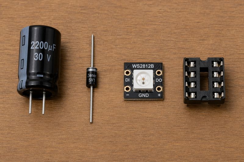
gemini-3.1-flash-image-preview (nano-banana-2) [web-search]

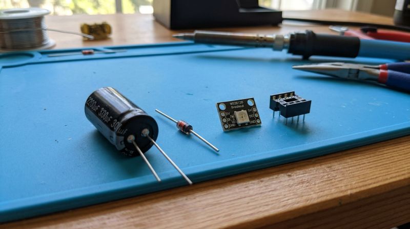
GPT-Image 2 vestigially handles text better, the rest the same, WS2812 pinout logic came out average.
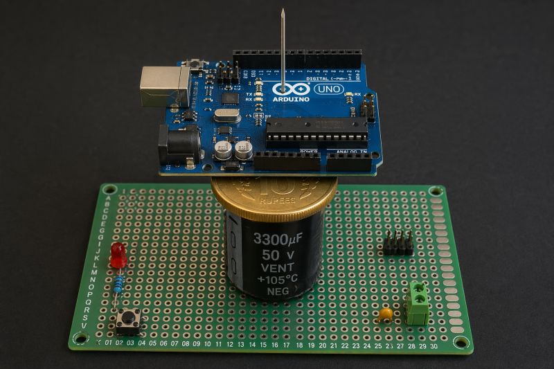
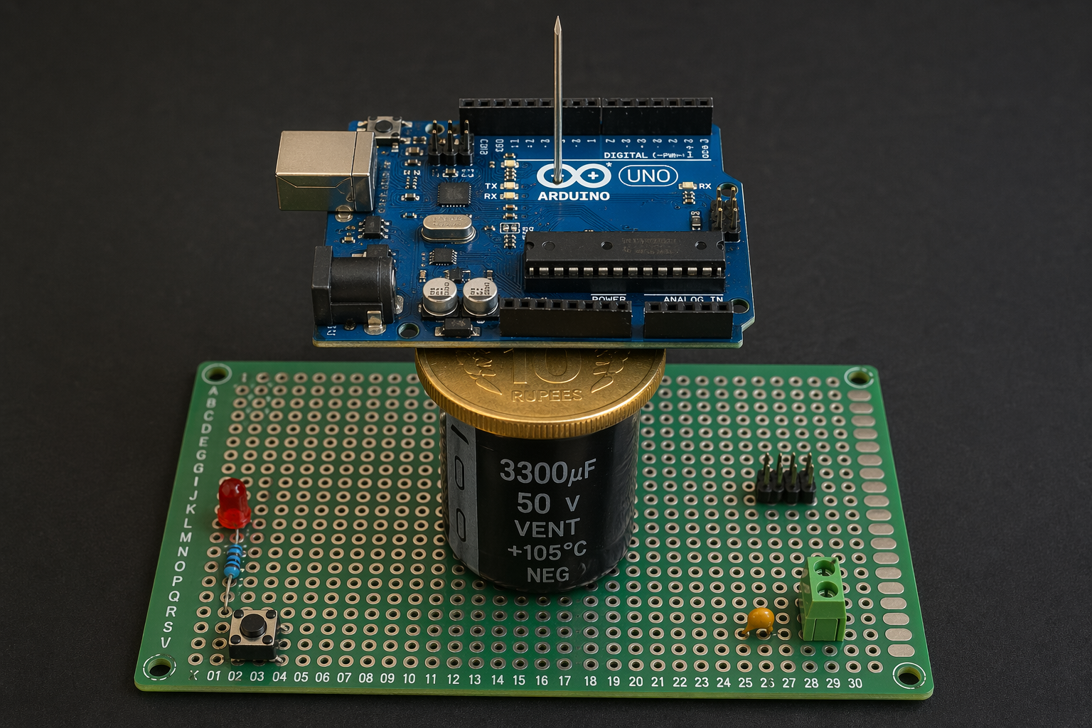
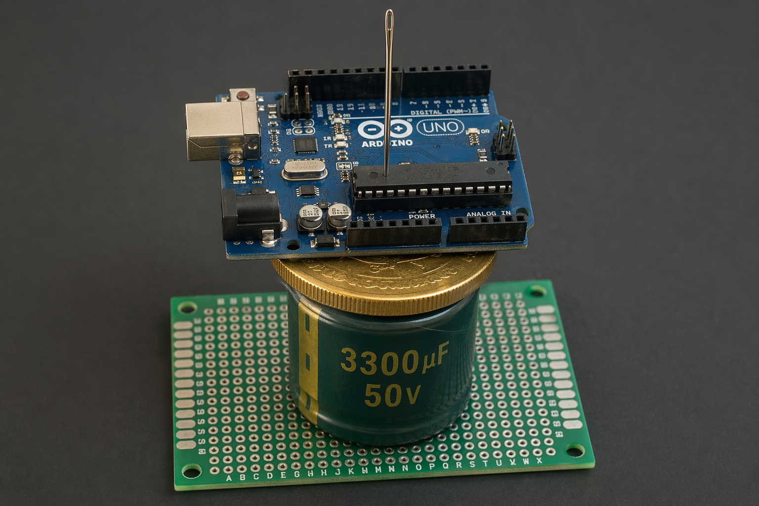
draw a proto board with 3300uF capacitor 50V on it, on capacitor put a gold coin, on coin put an Arduino UNO, and on Arduino UNO put needle
gpt-image-2 (medium)

gemini-3.1-flash-image-preview (nano-banana-2) [web-search]
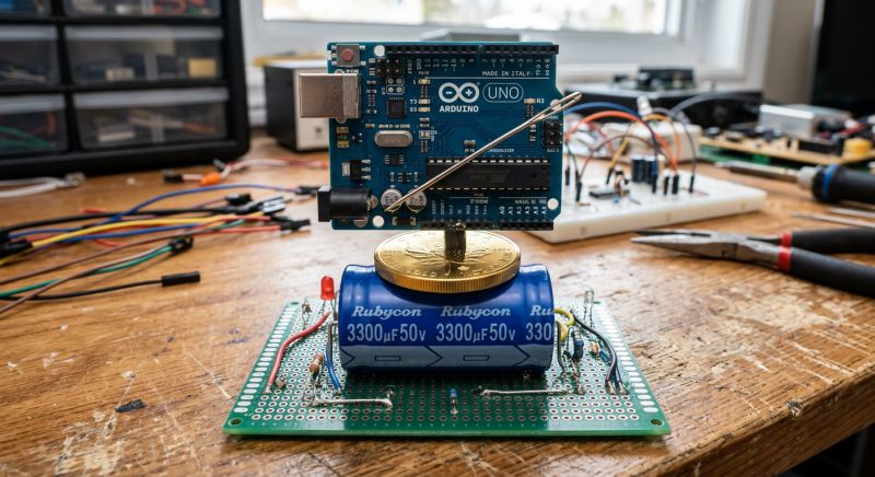
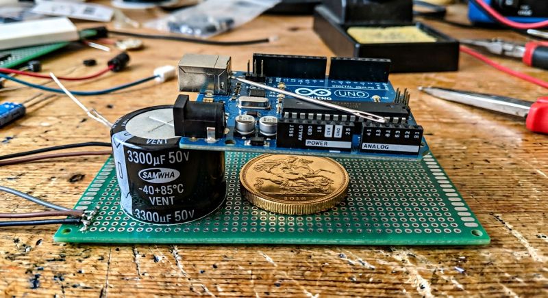
These needle alignments are unnatural, but GPT-Image 2 did a slightly better job with the relationships between objects, they came out more natural.
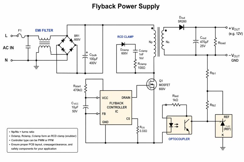
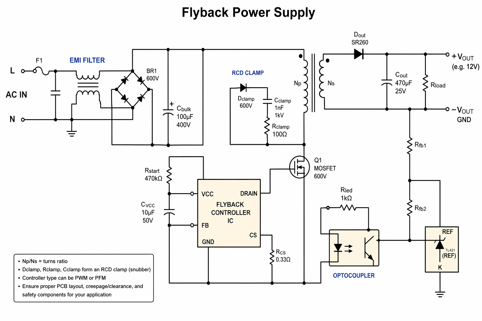
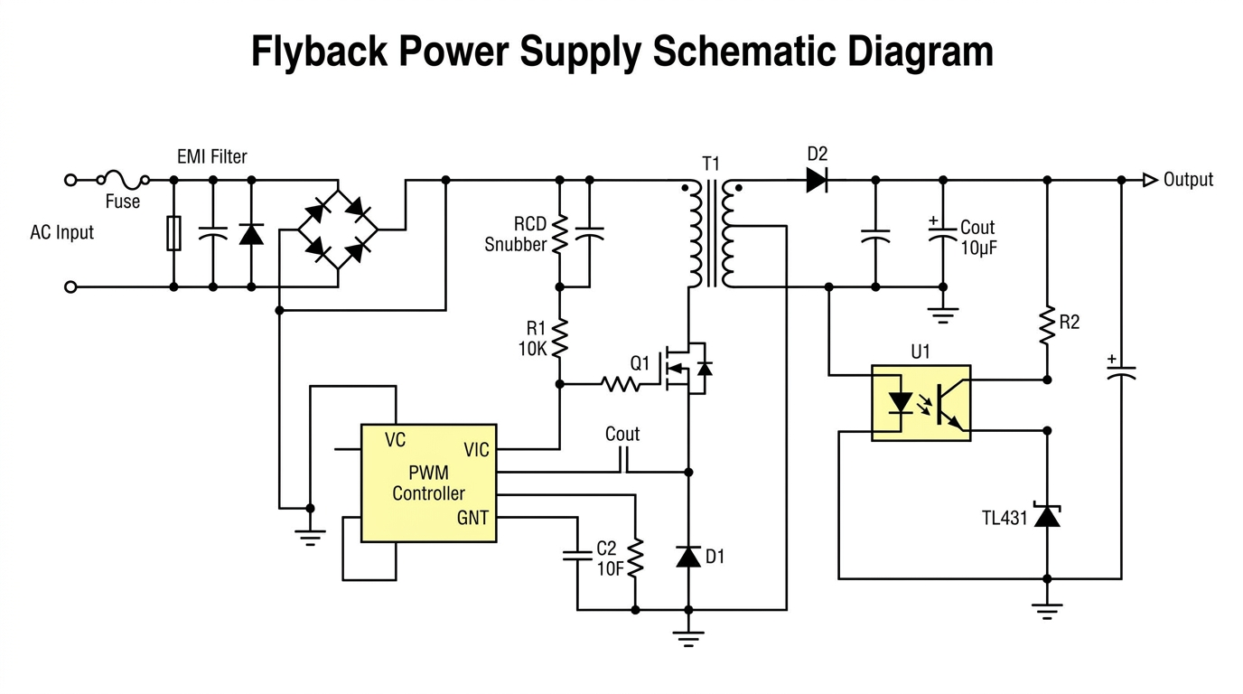
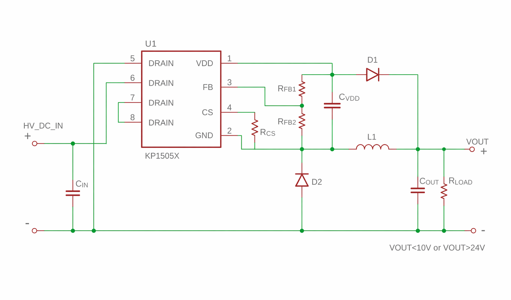
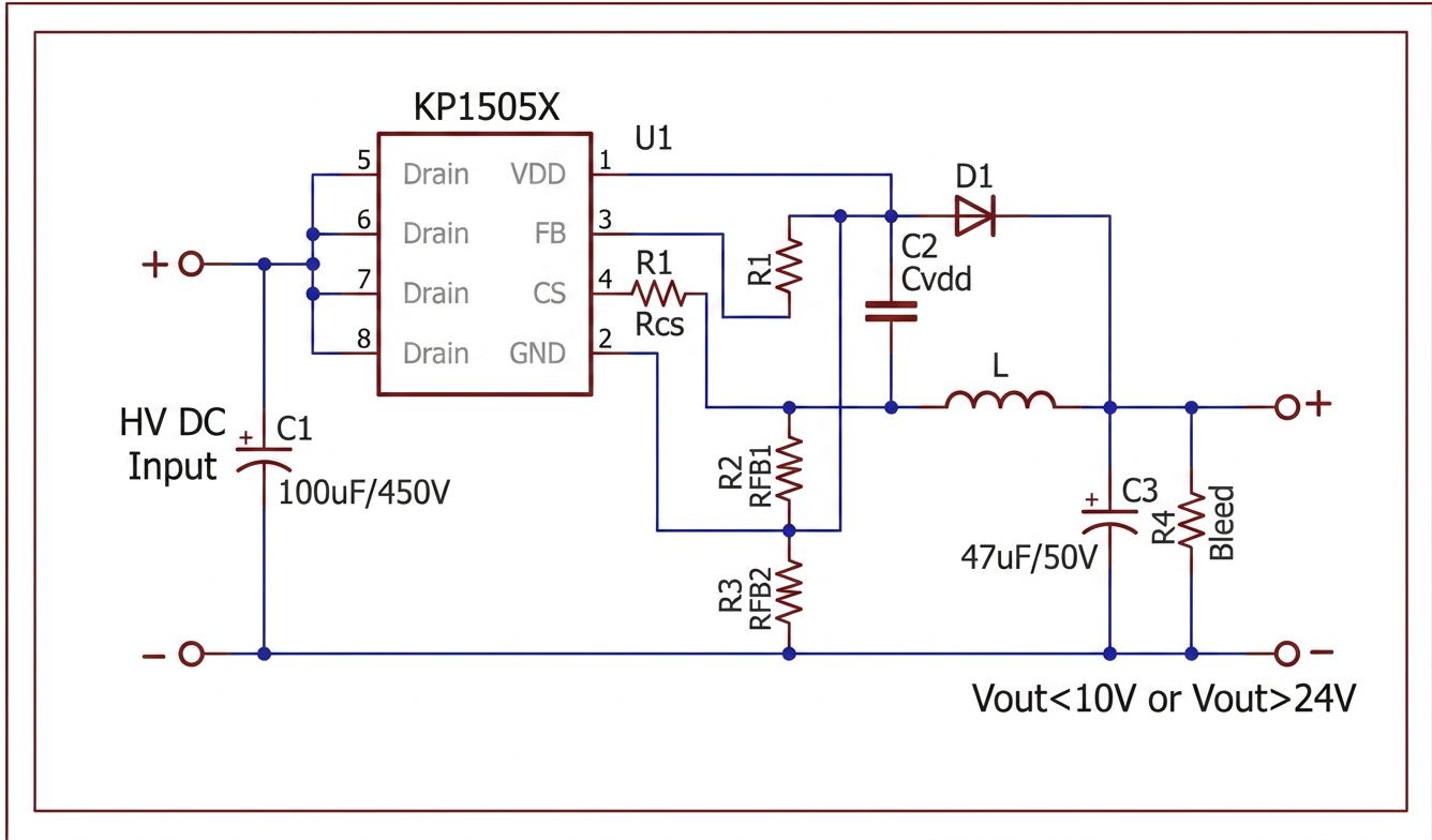
flyback power supply schematic
gpt-image-2 (medium)
gemini-3.1-flash-image-preview (nano-banana-2) [web-search]
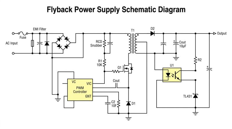
GPT-Image 2 likes to apply a block of text to the images, but the sense in the images is not there. Still that shorted EMI FILTER... fB pin on the ground... aND the whole bit with the reference voltage taken from ground.
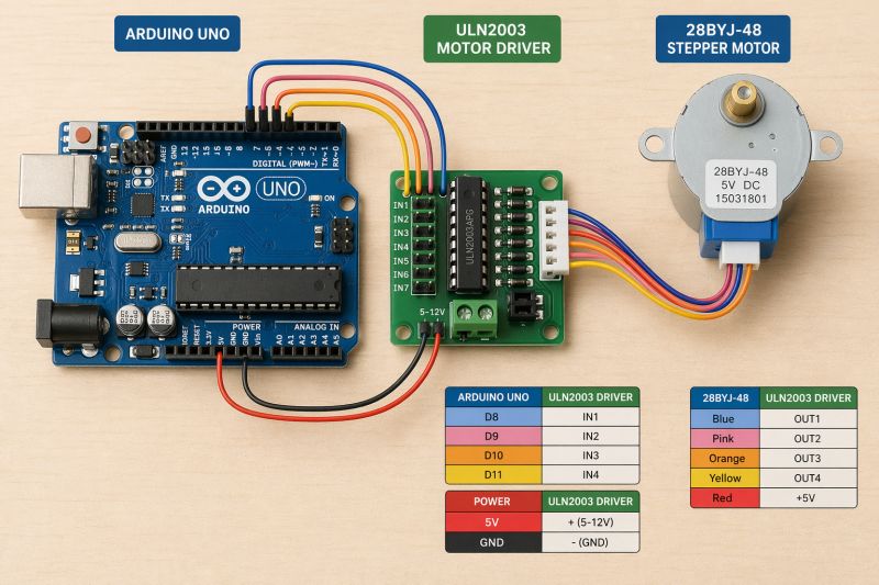
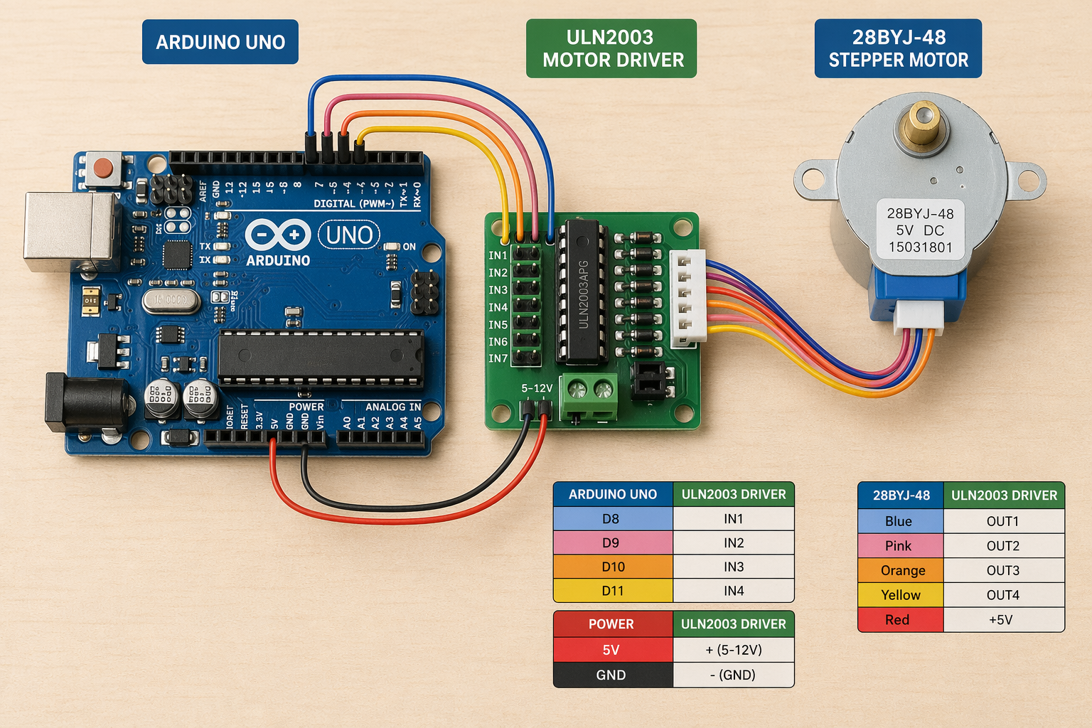
Arduino UNO with 28BYJ-48 and motor driver connect by wires
gpt-image-2 (medium)
gemini-3.1-flash-image-preview (nano-banana-2) [web-search]
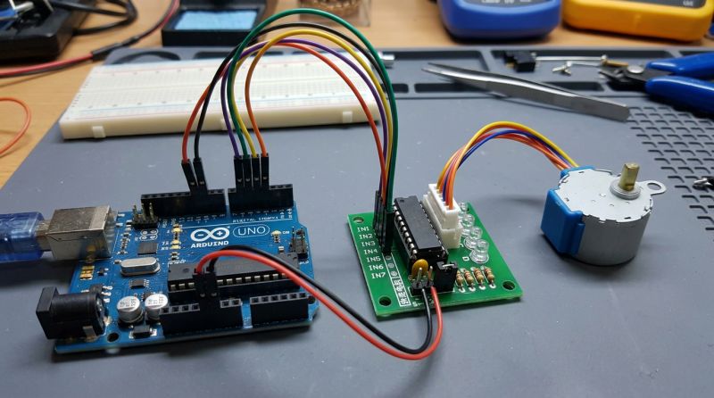
Similarly, but it is apparent that GPT-Image 2 likes diagrams and tables and text. Interestingly, both models know where the power and ground are on the Arduino.
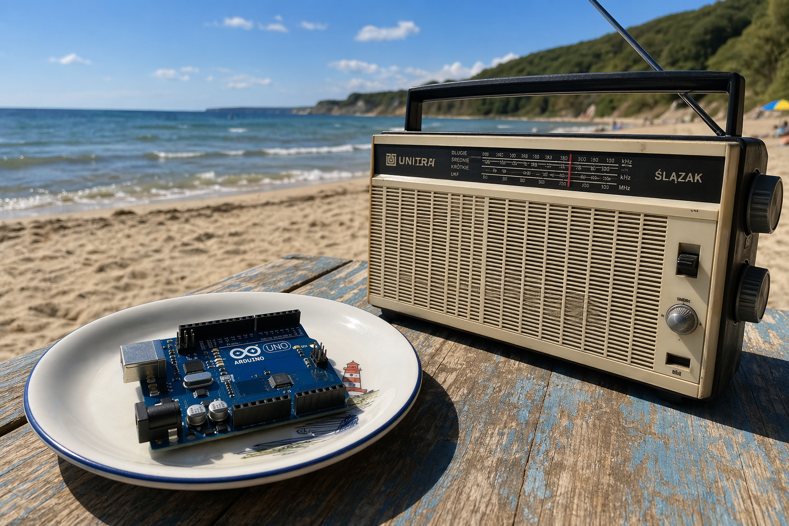
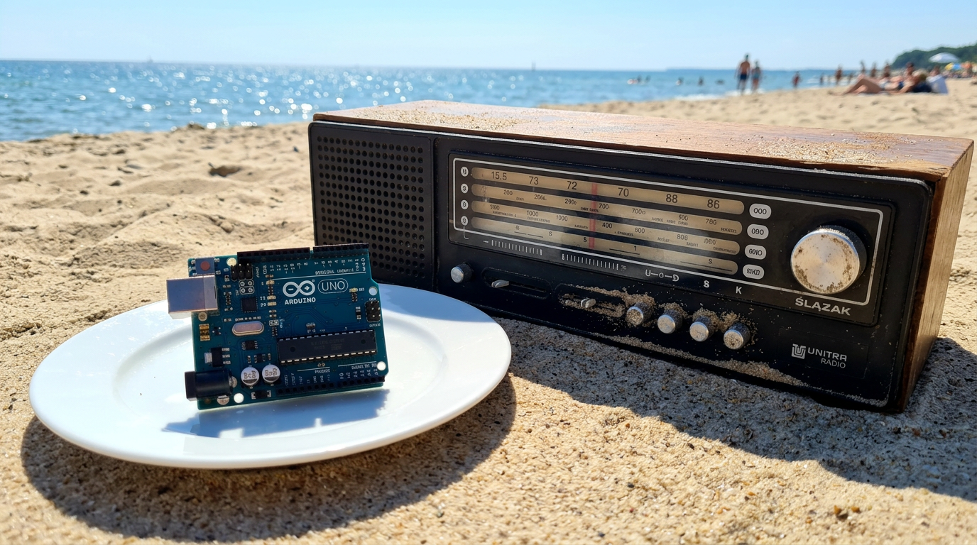
Arduino UNO on a plate, next to old Unitra Silesian radio on beach during sunny day
gpt-image-2 (medium)

gemini-3.1-flash-image-preview (nano-banana-2) [web-search]

Very similar, although the option with search mapped the radio better. I think it searched for them.
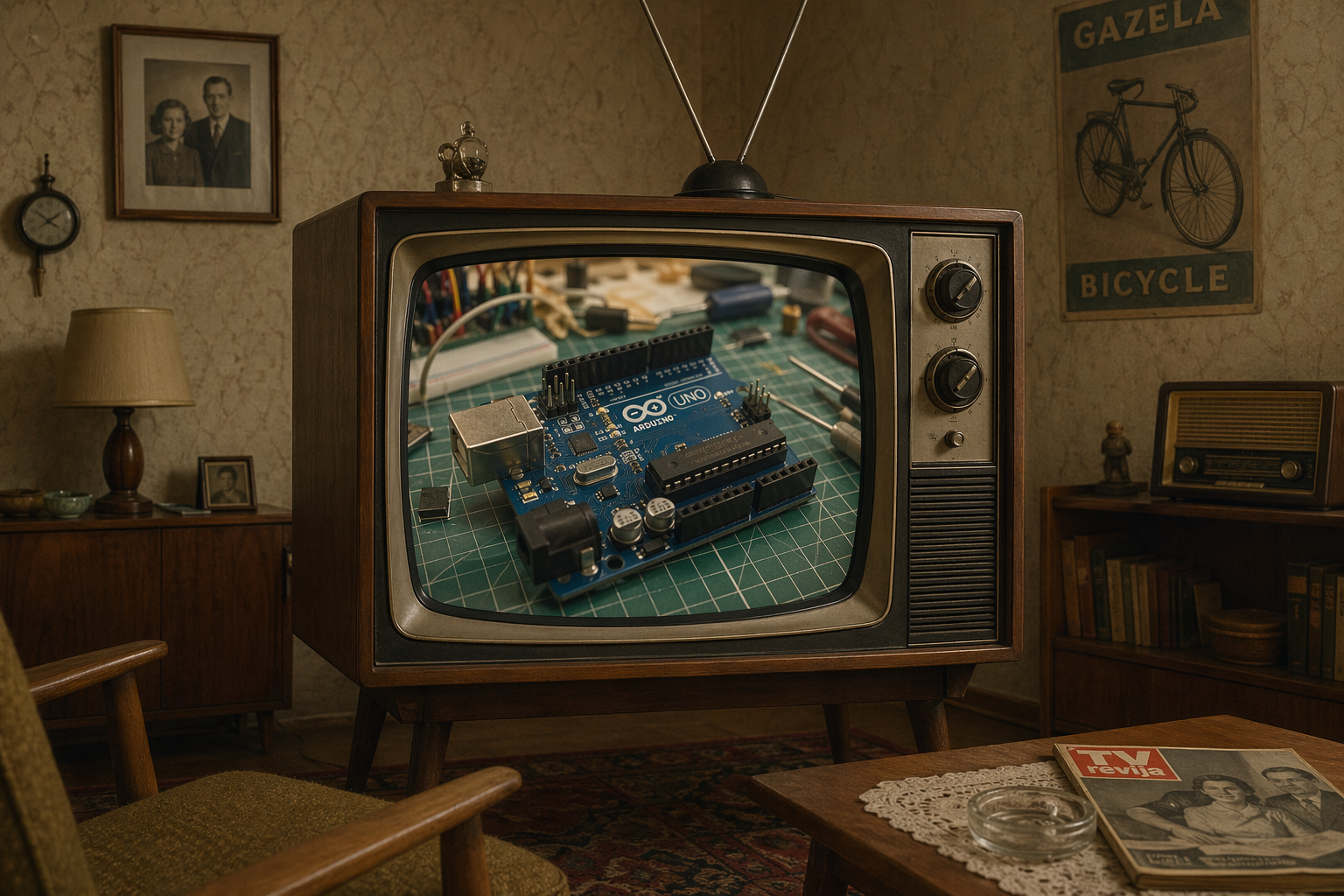
1960 old room with TV showing modern Arduino UNO in workshop
gpt-image-2 (medium)

gemini-3.1-flash-image-preview (nano-banana-2) [web-search]

I find it difficult to give a verdict on which is better.
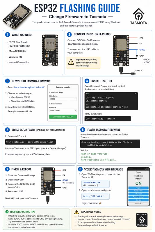
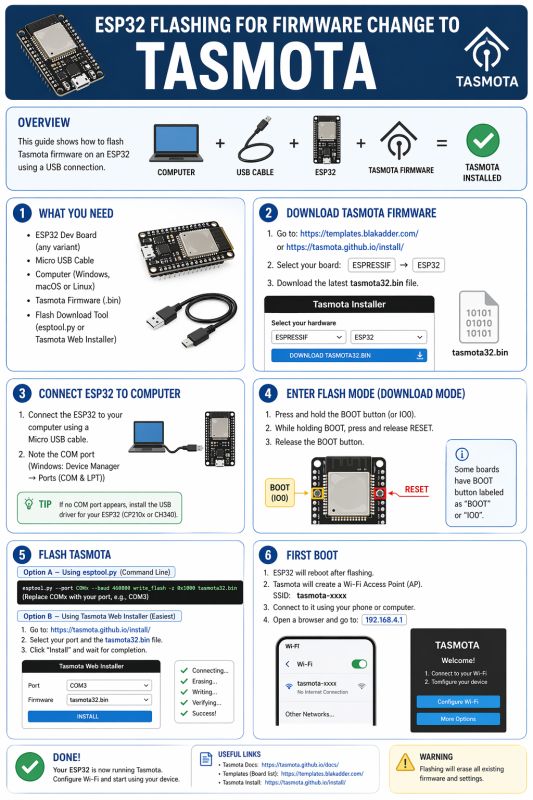
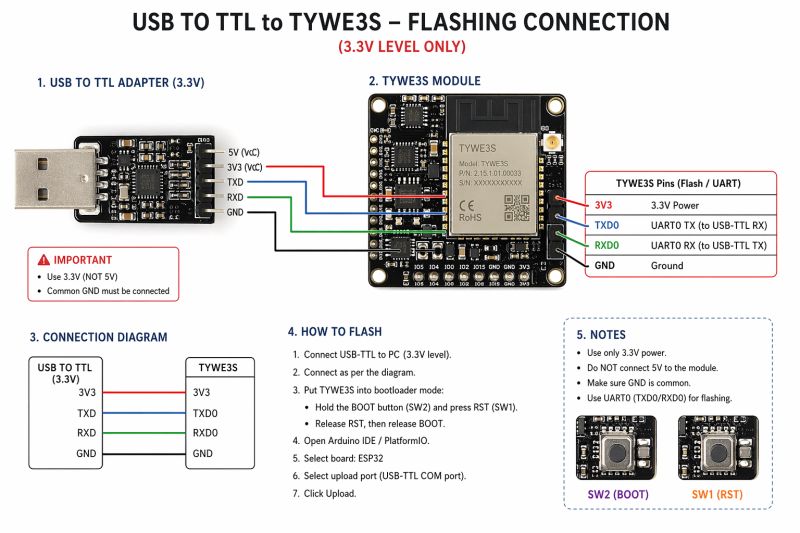
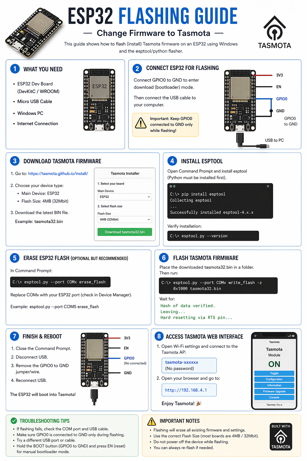
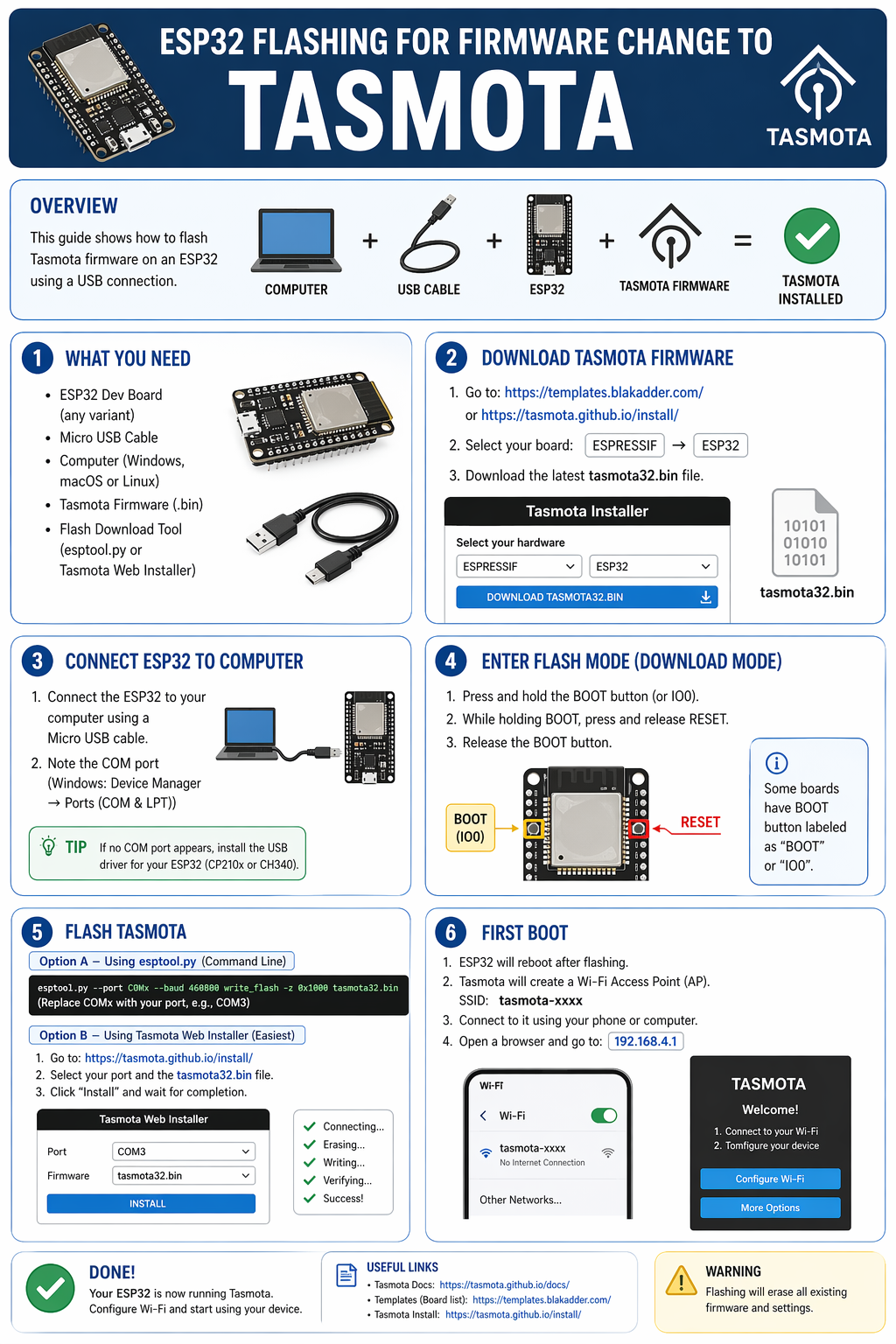
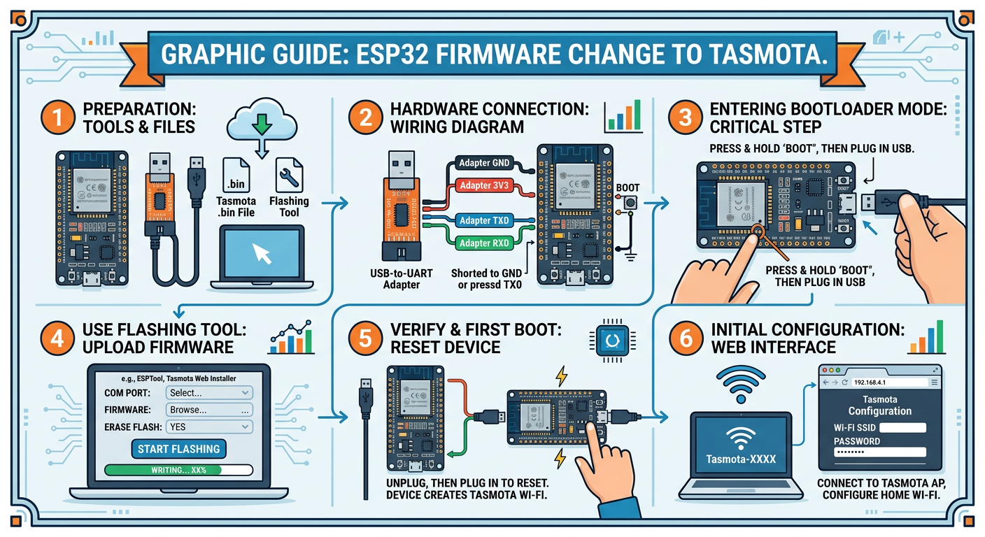
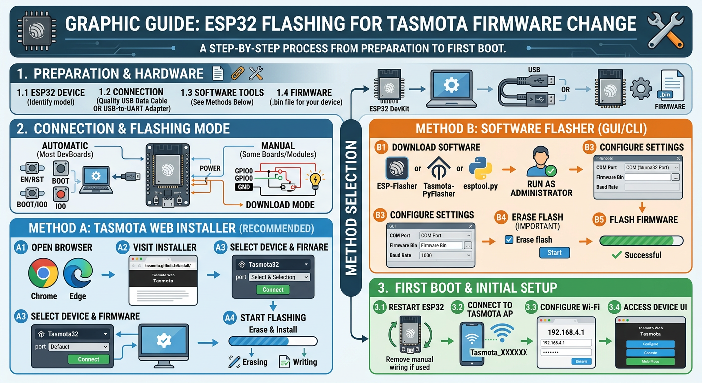
draw graphic guide - ESP32 flashing for firmware change to Tasmota
gpt-image-2 (medium)
gemini-3.1-flash-image-preview (nano-banana-2) [web-search]
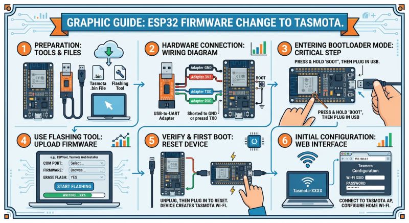
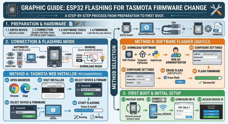
On this board you don't need to manually short GPIO0 to ground.... interesting, the rest came out pretty good. Nicer infographics are made by this GPT-Image 2.
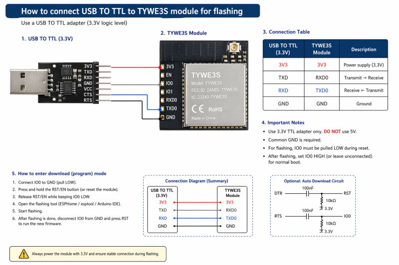
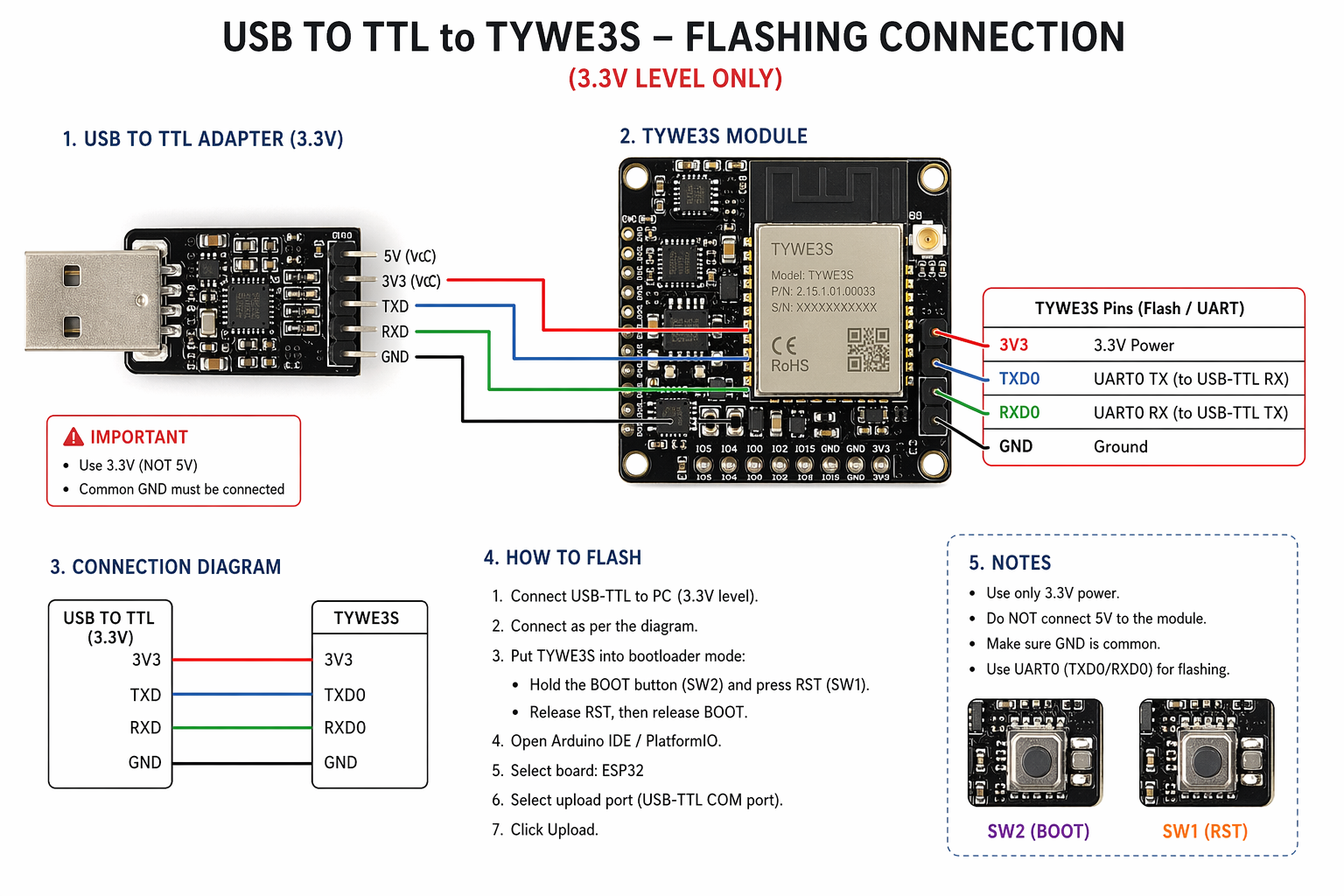
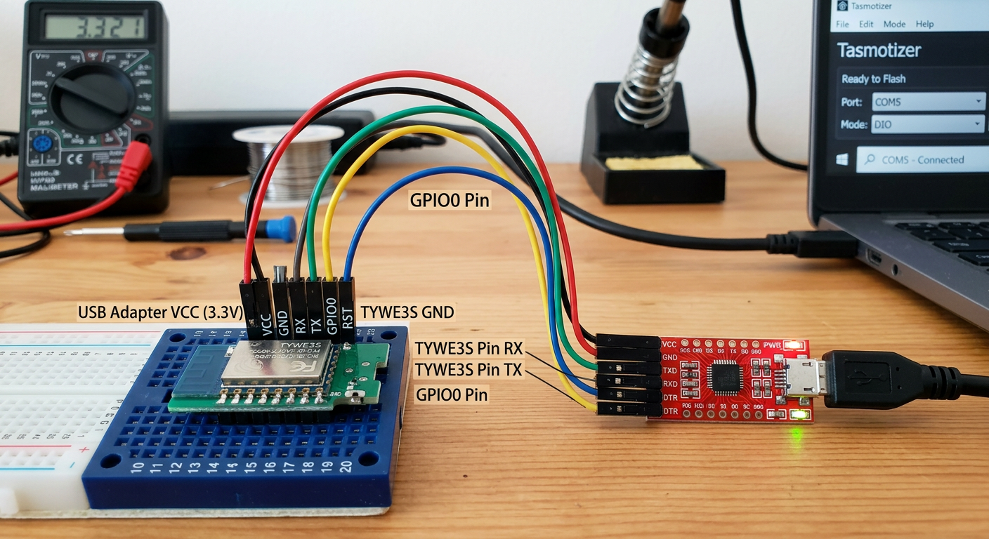
So how to connect USB TO TTL to TYWE3S module for flashing?
gpt-image-2 (medium)
gemini-3.1-flash-image-preview (nano-banana-2) [web-search]
A bit faint, wrong, pinout is also wrong. This is how you can burn a module. A disastrous tool.
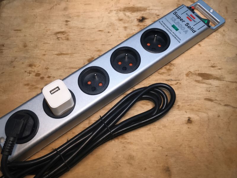
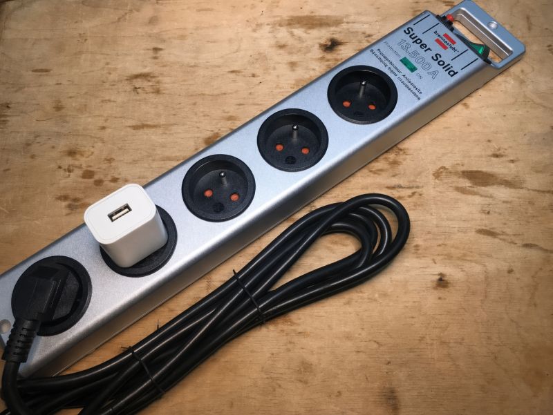
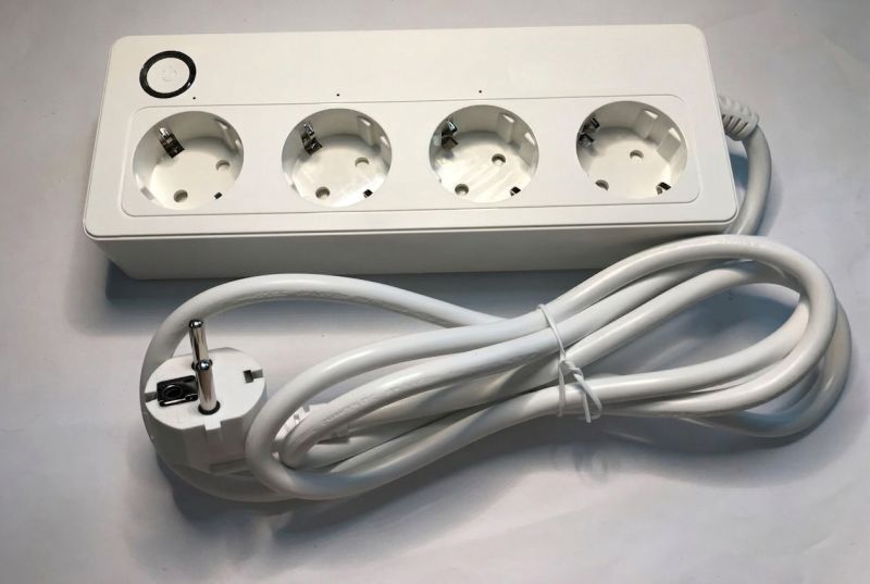
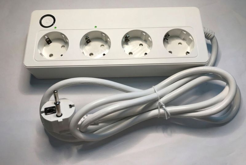
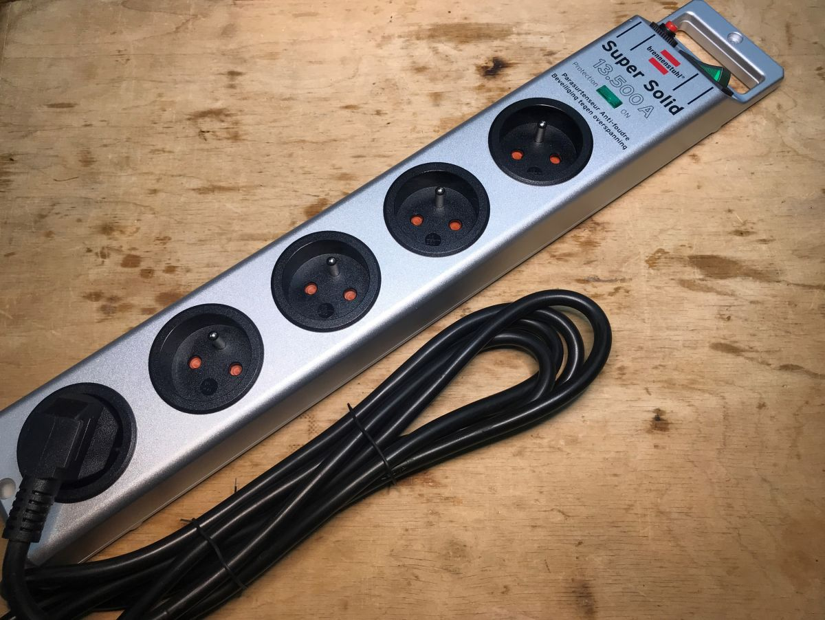
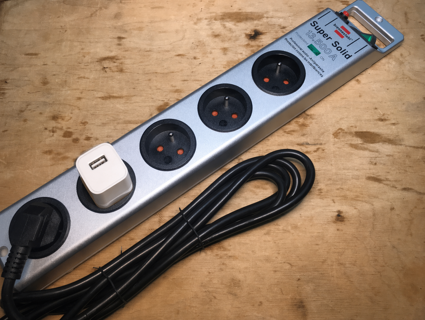
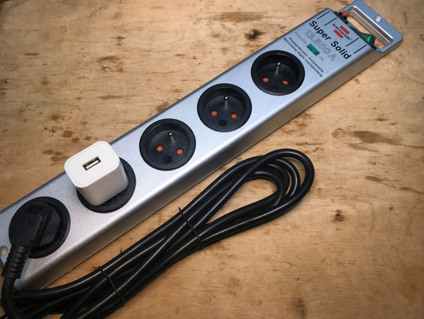
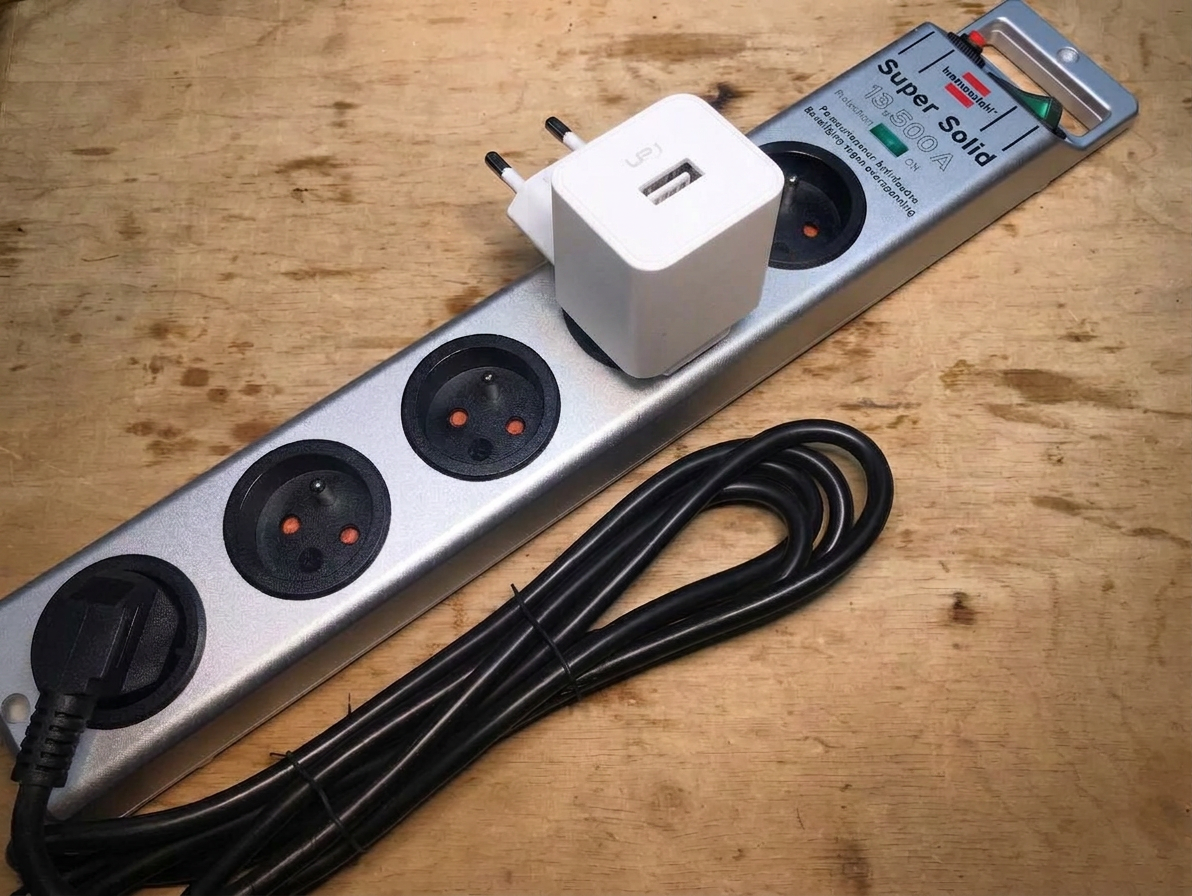
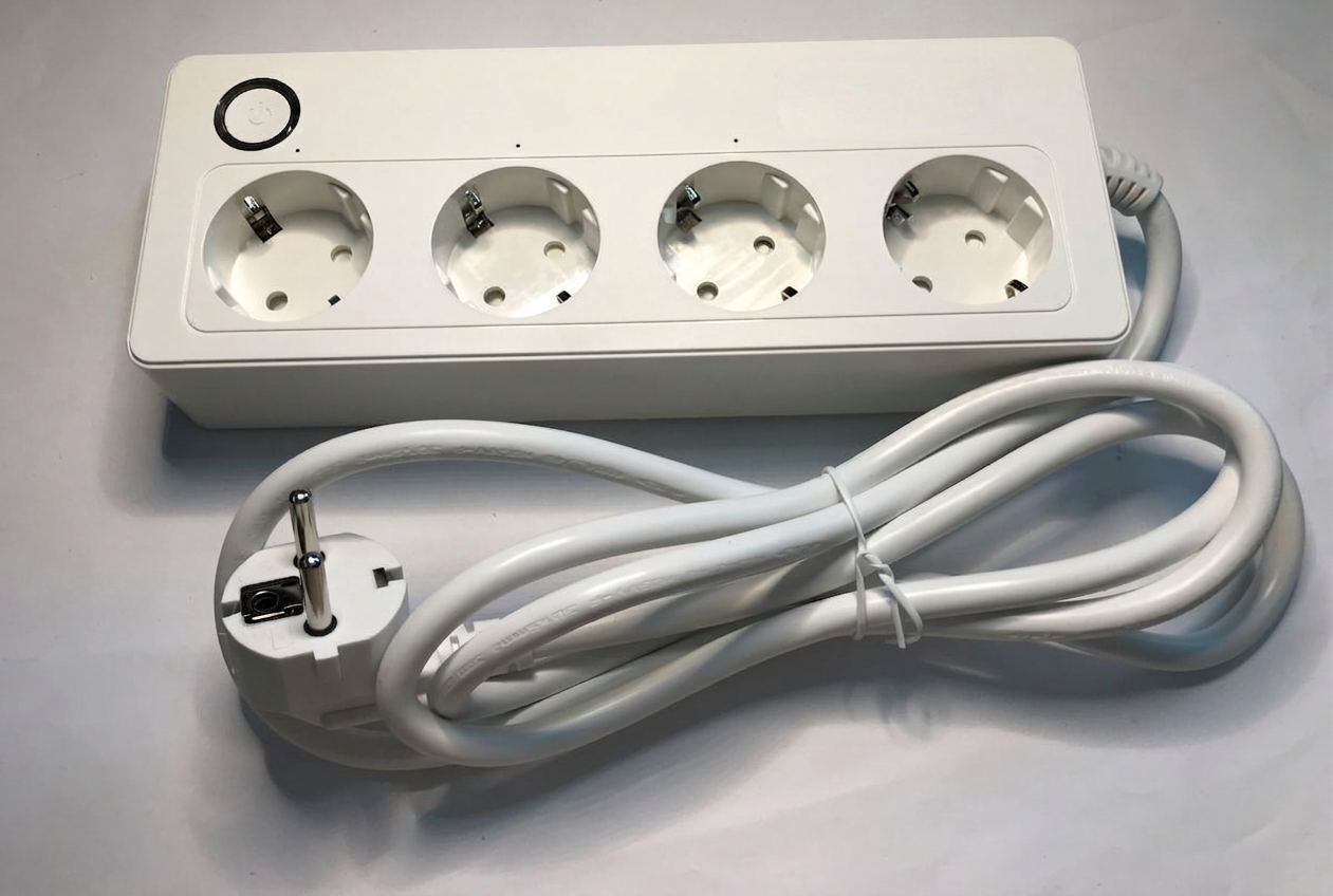
please plug a white phone charger with empty USB A slot into my power strip

gpt-image-2 (medium)
gpt-image-2 (medium)
gemini-3.1-flash-image-preview (nano-banana-2) [web-search]
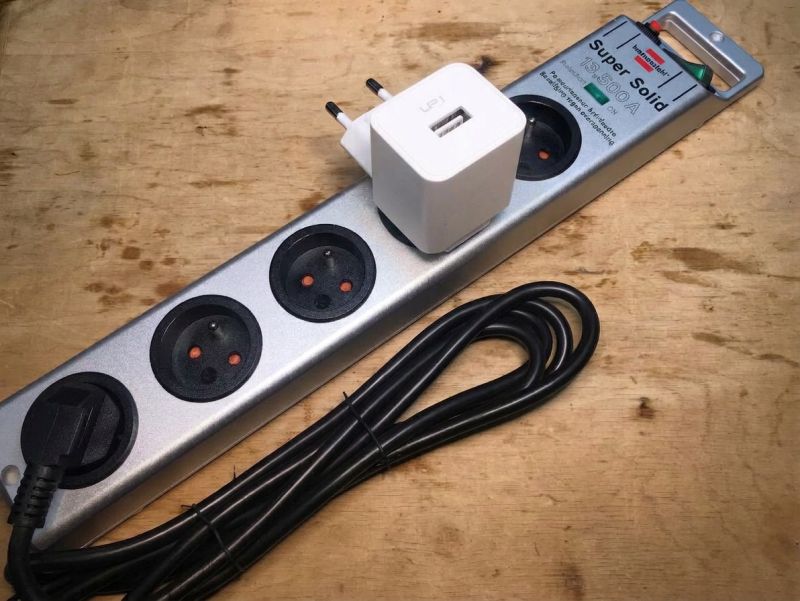
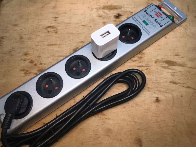
Banana got it wrong once, and yes both average.
change image to remove Flash Memory Chip so only empty pads are visible

gpt-image-2 (medium)


gemini-3.1-flash-image-preview (nano-banana-2) [web-search]
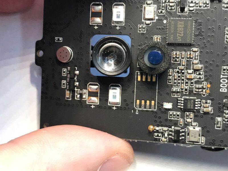

GPT-Image 2 total fail, doesn't seem to understand what Flash memory is.
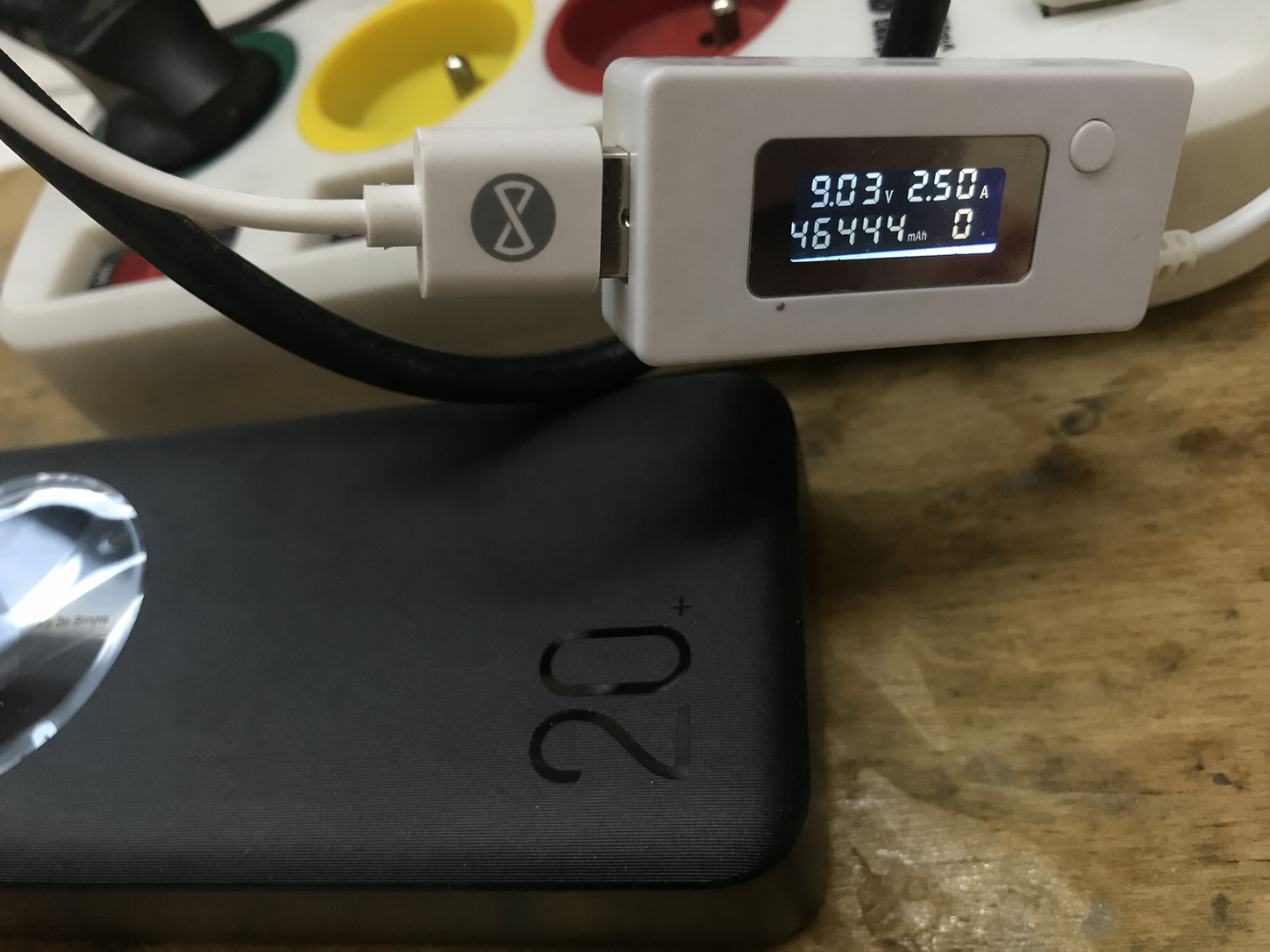
Change voltage to 9.03V , current to 2.50A and capacity to 46444mAh

gpt-image-2 (medium)

gpt-image-2 (medium)
gemini-3.1-flash-image-preview (nano-banana-2) [web-search]
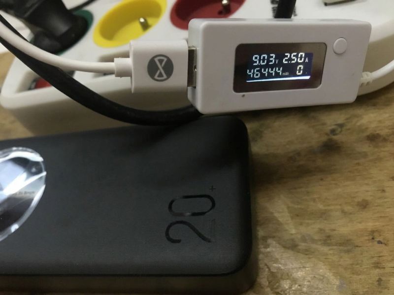
Both managed.
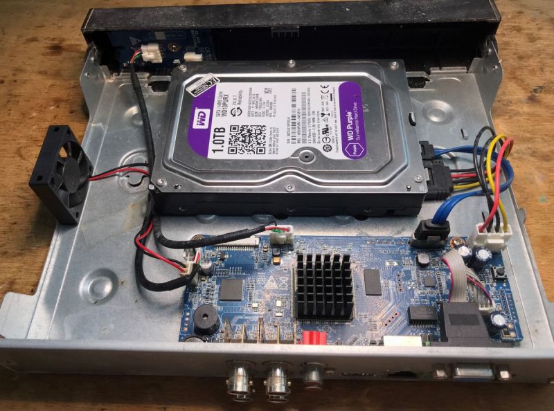
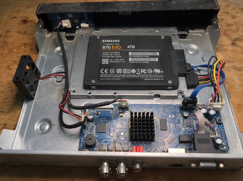
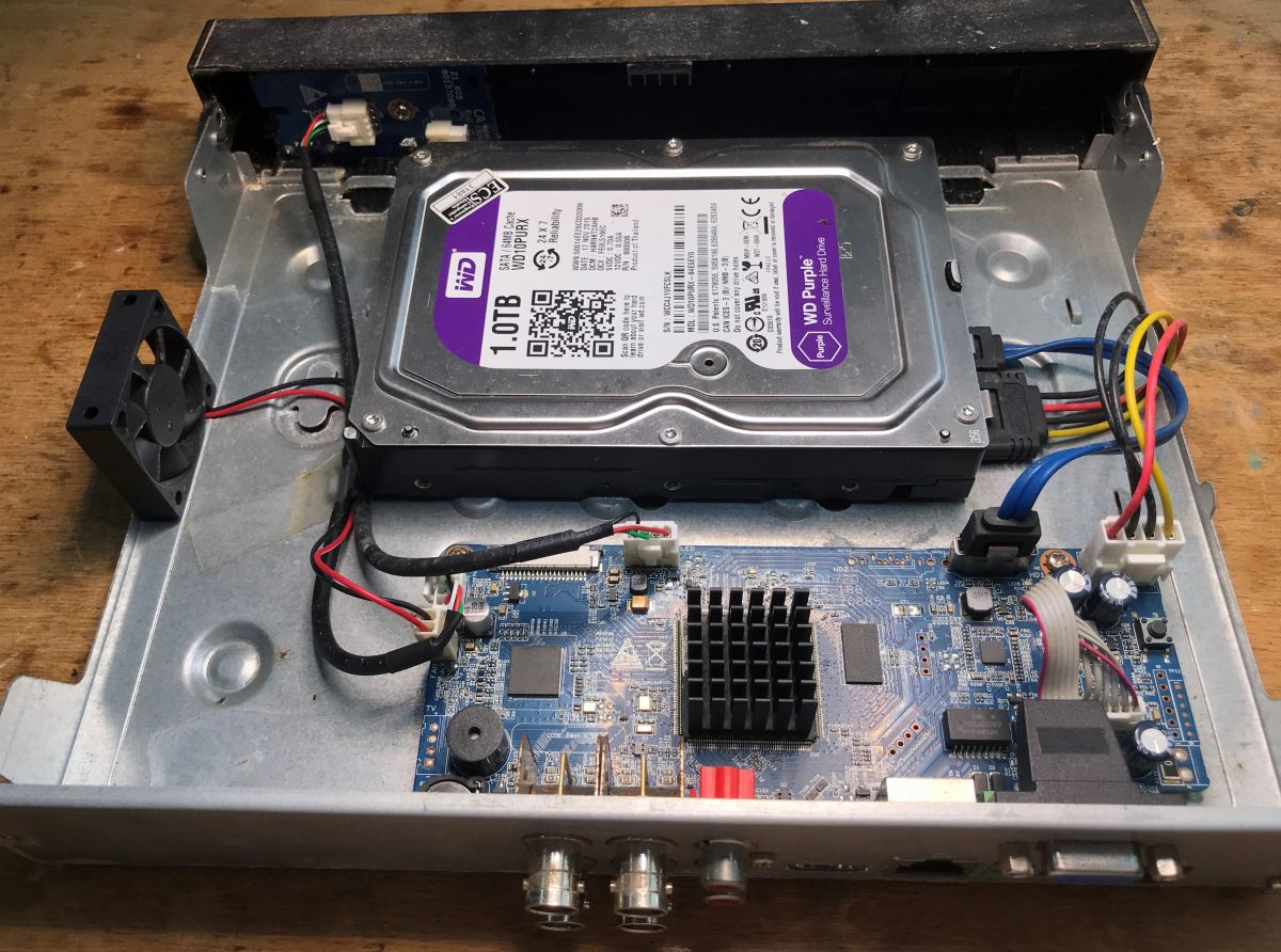
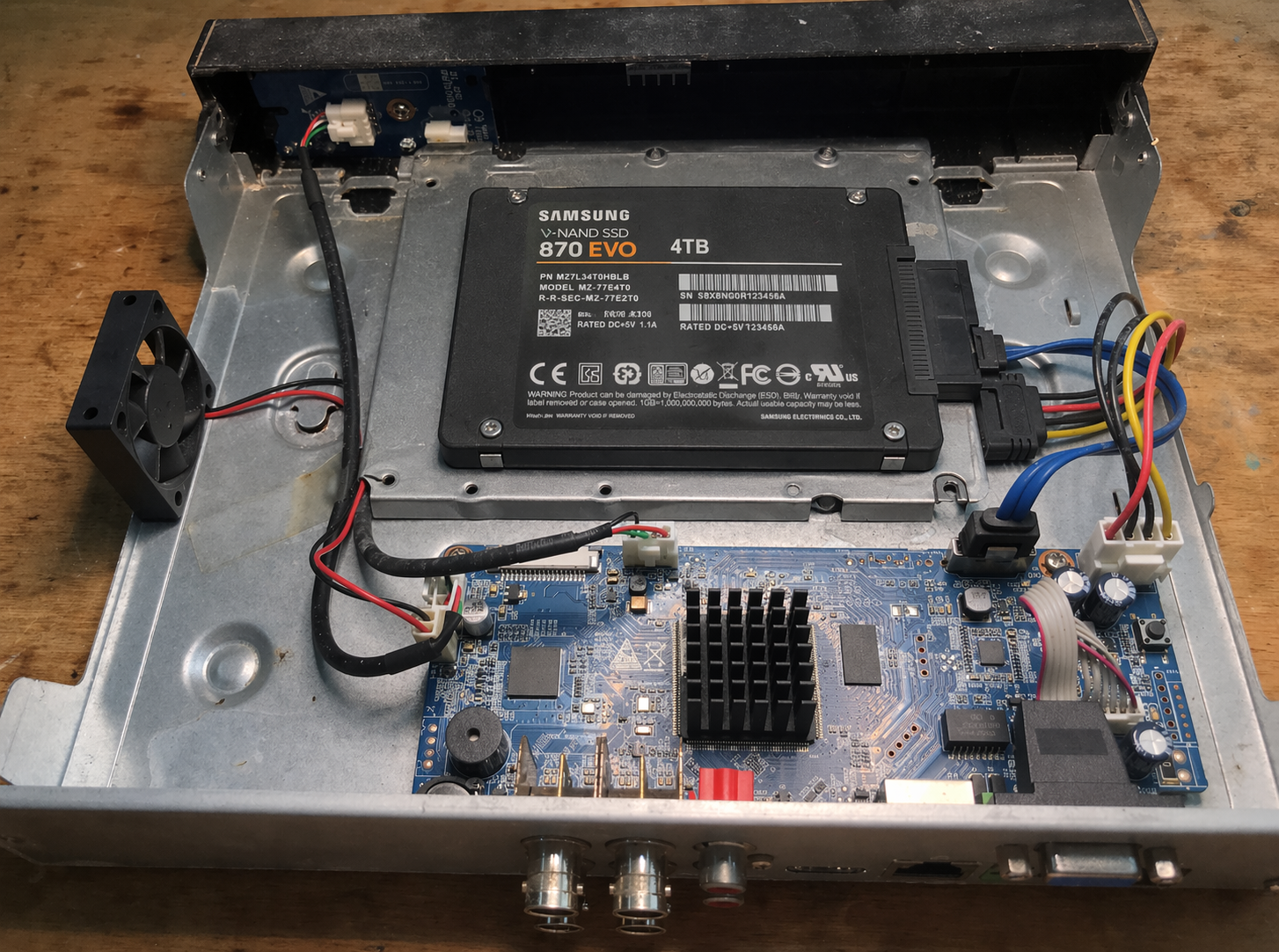
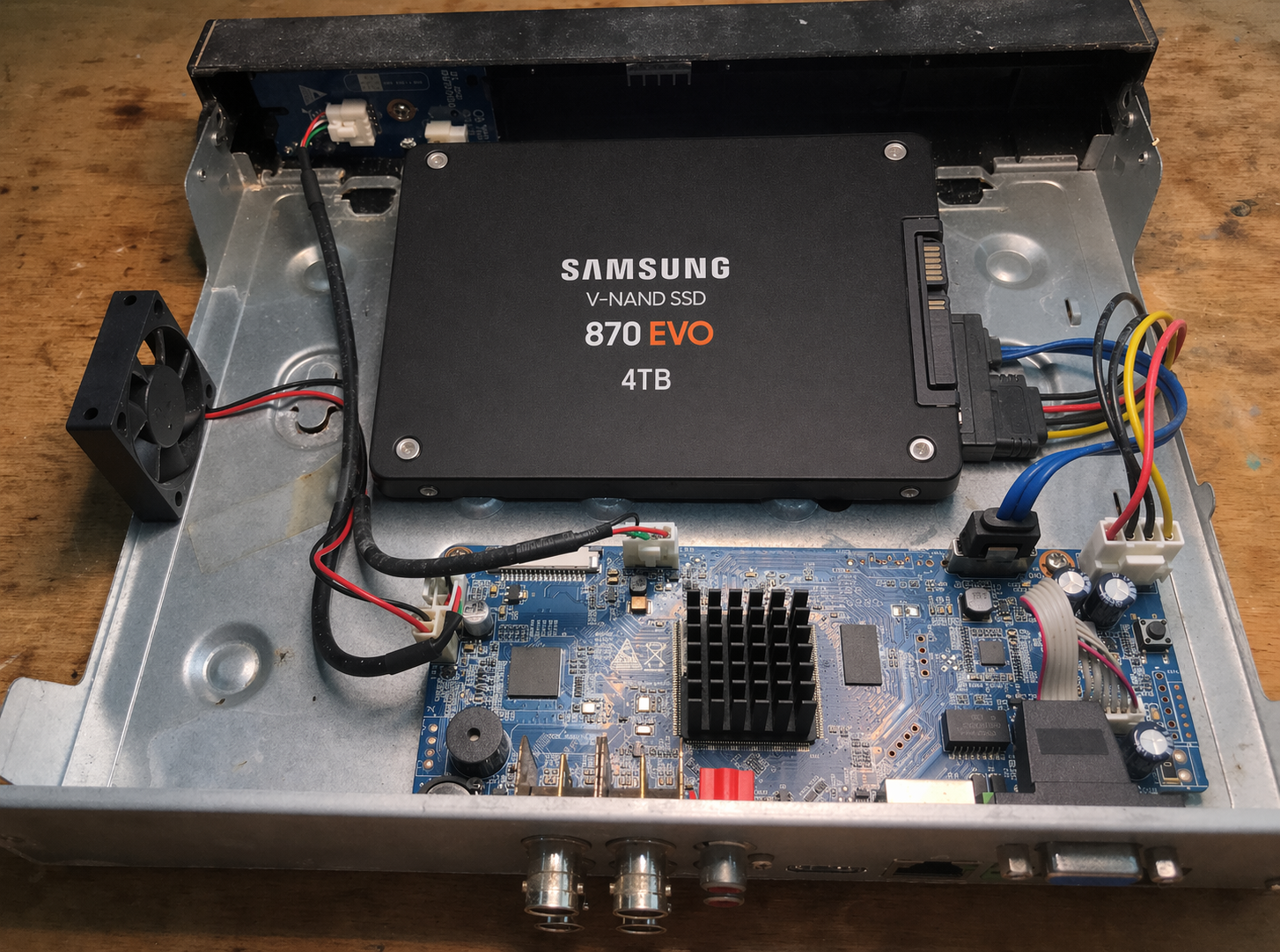
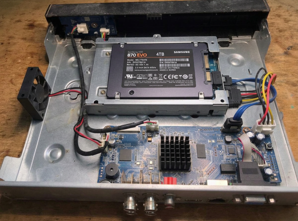
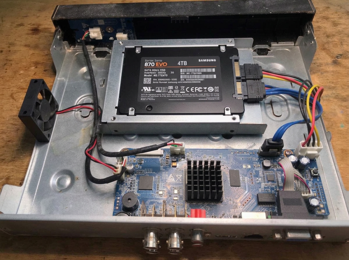
change hdd to 2.5" SSD Samsung EVO 4TB
gpt-image-2 (medium)
gpt-image-2 (medium)

gemini-3.1-flash-image-preview (nano-banana-2) [web-search]
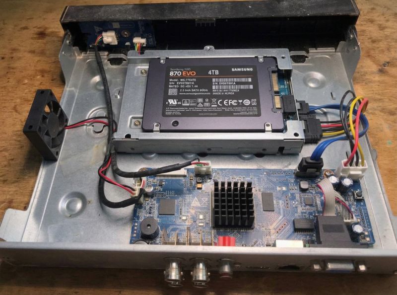
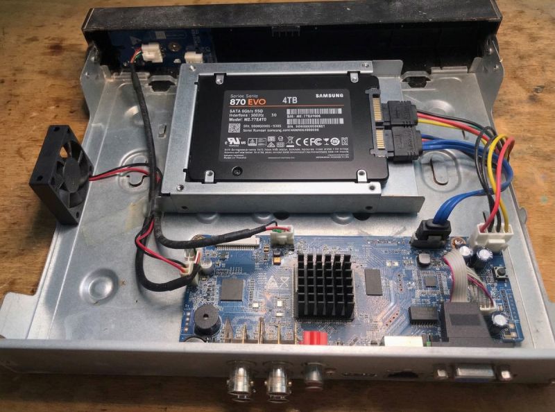
Both generators have a problem.
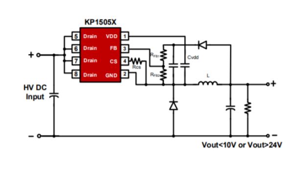
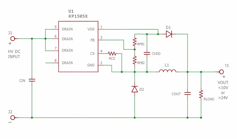
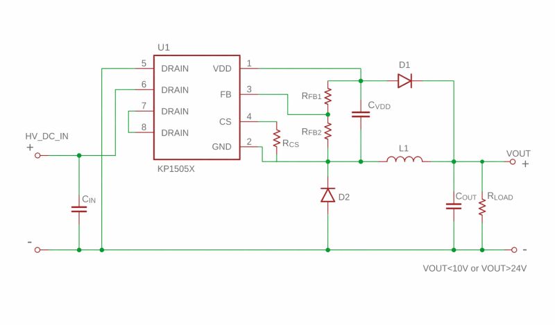
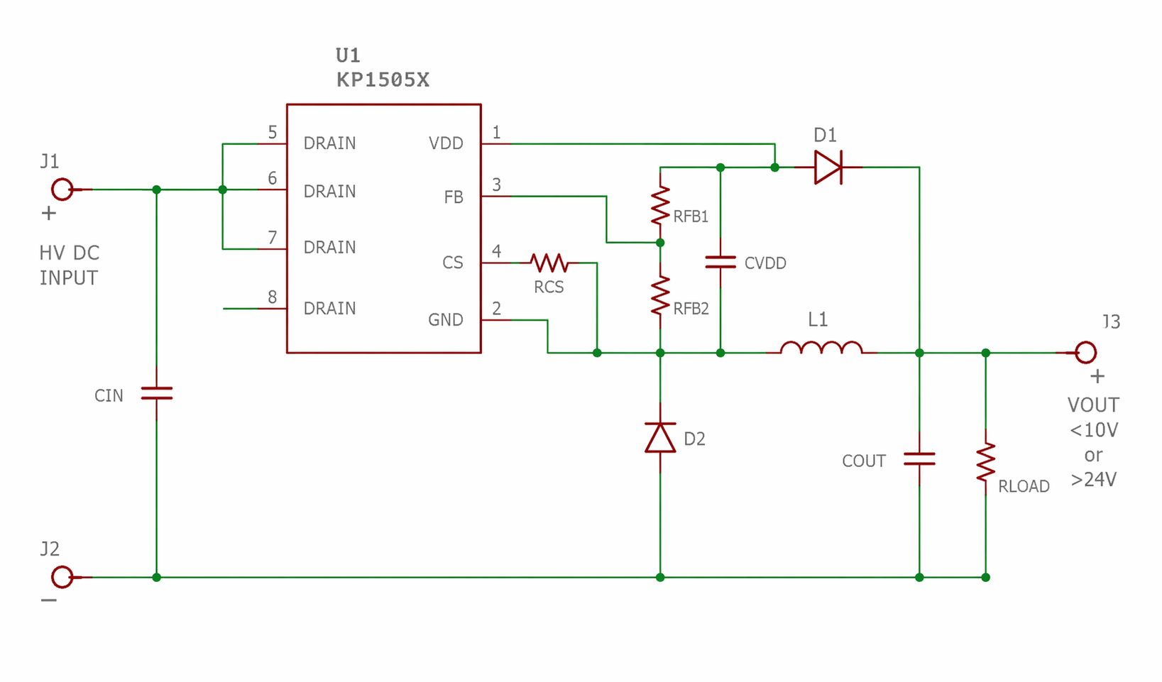
convert schematic to cadsoft eagle style and format
gpt-image-2 (medium)
gpt-image-2 (medium)
gemini-3.1-flash-image-preview (nano-banana-2) [web-search]
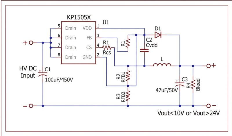
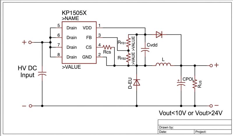
GPT-Image 2 transferred the style better, but also messed up the schema.
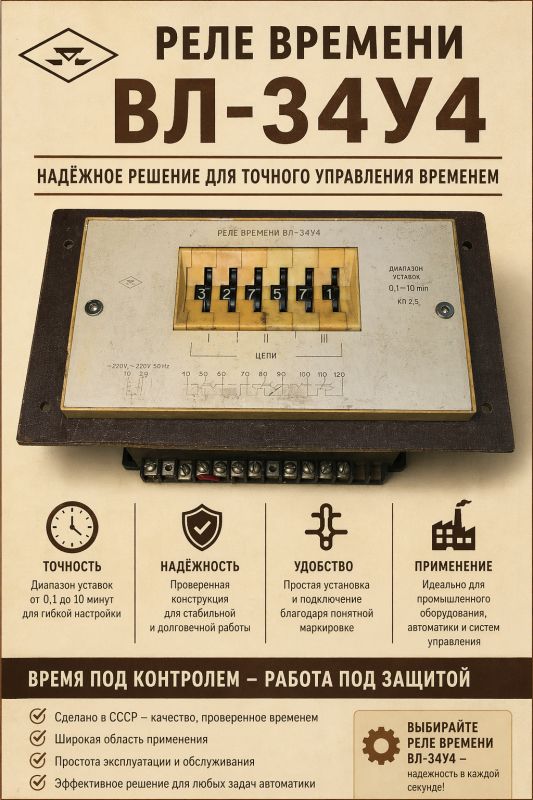
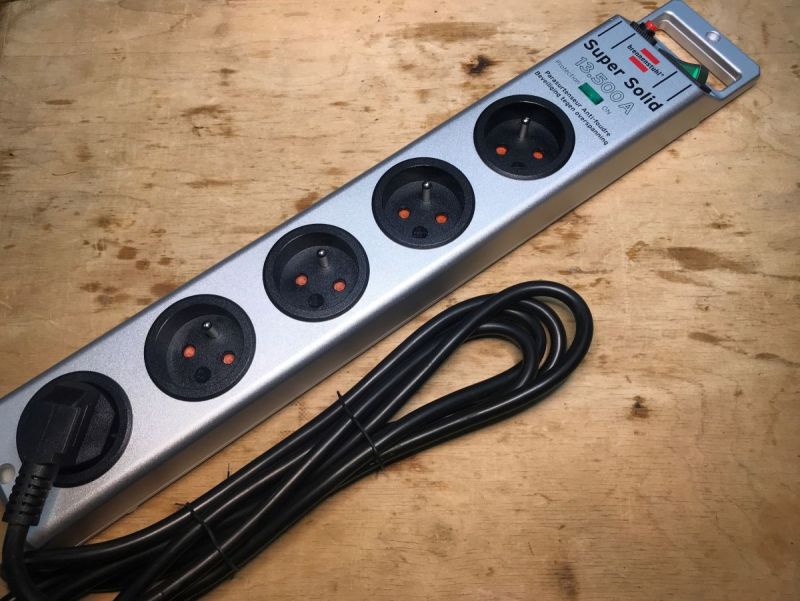
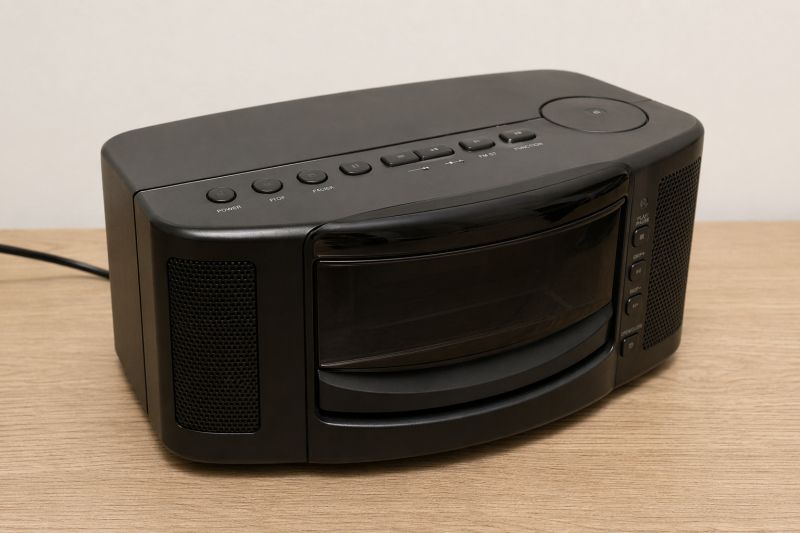
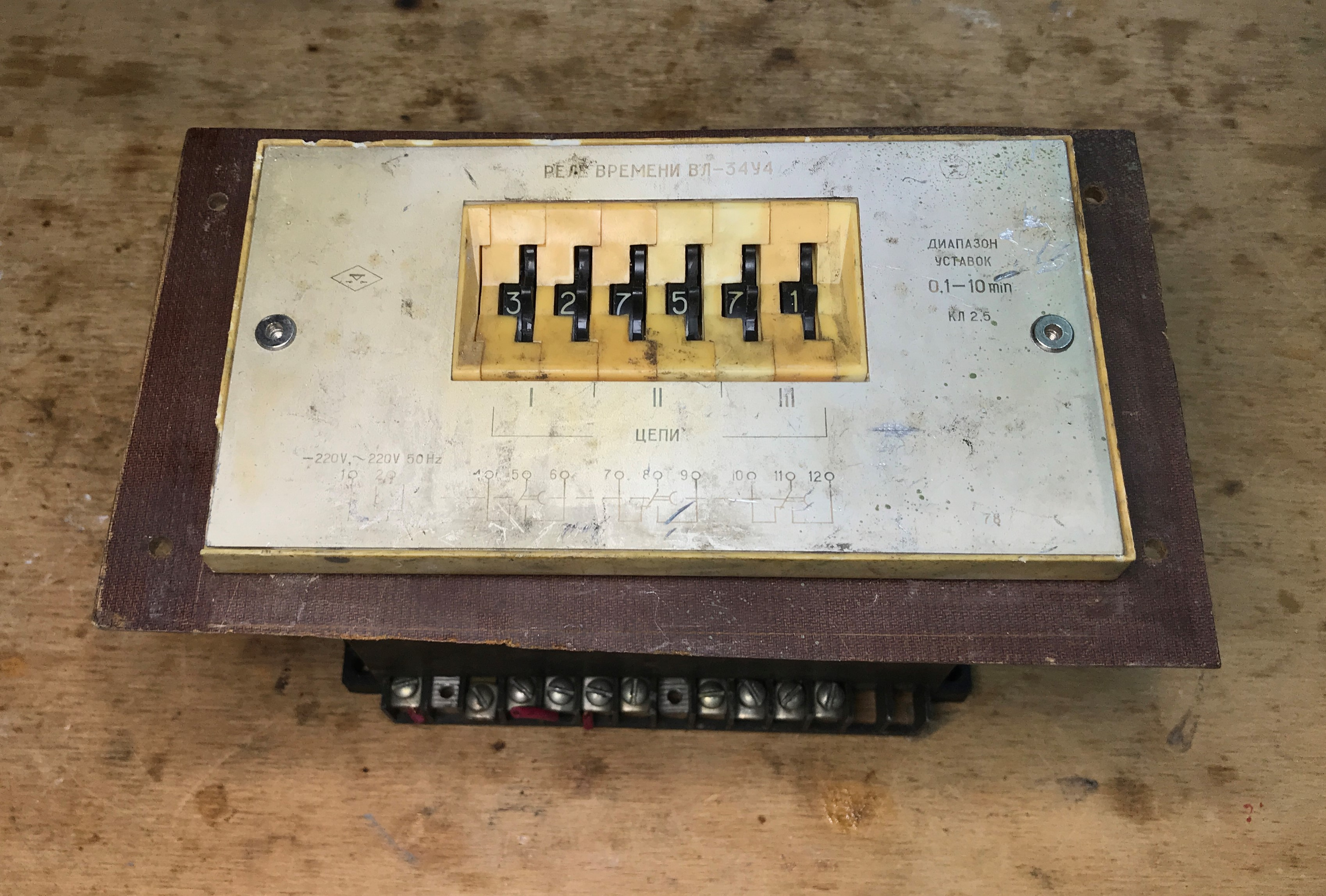
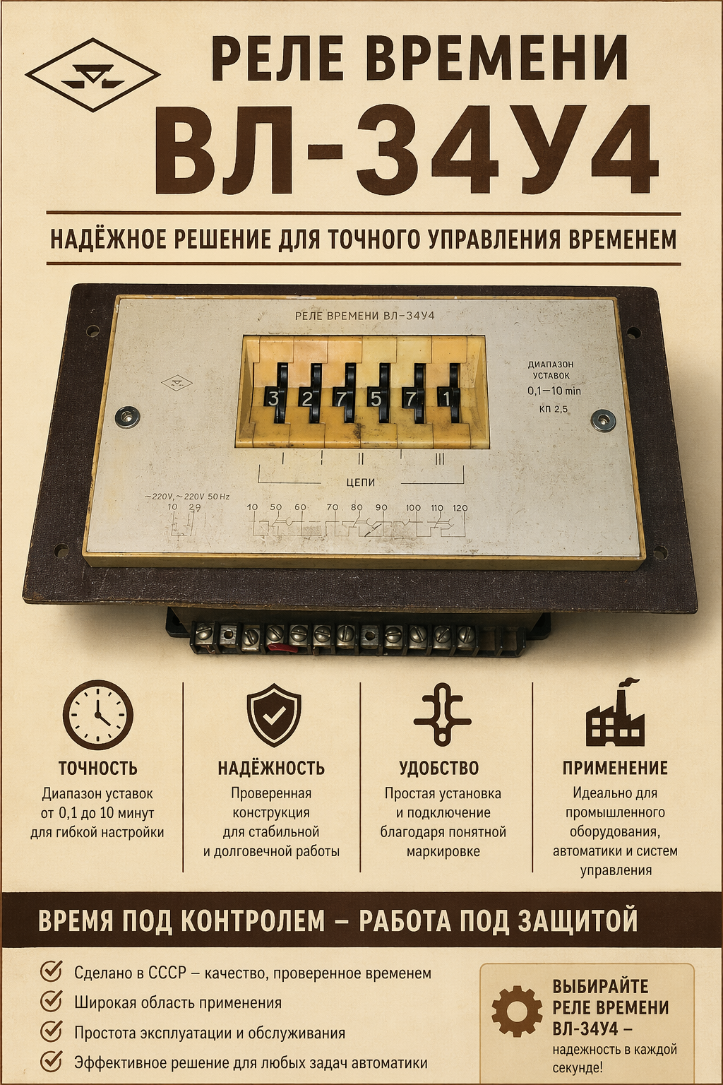
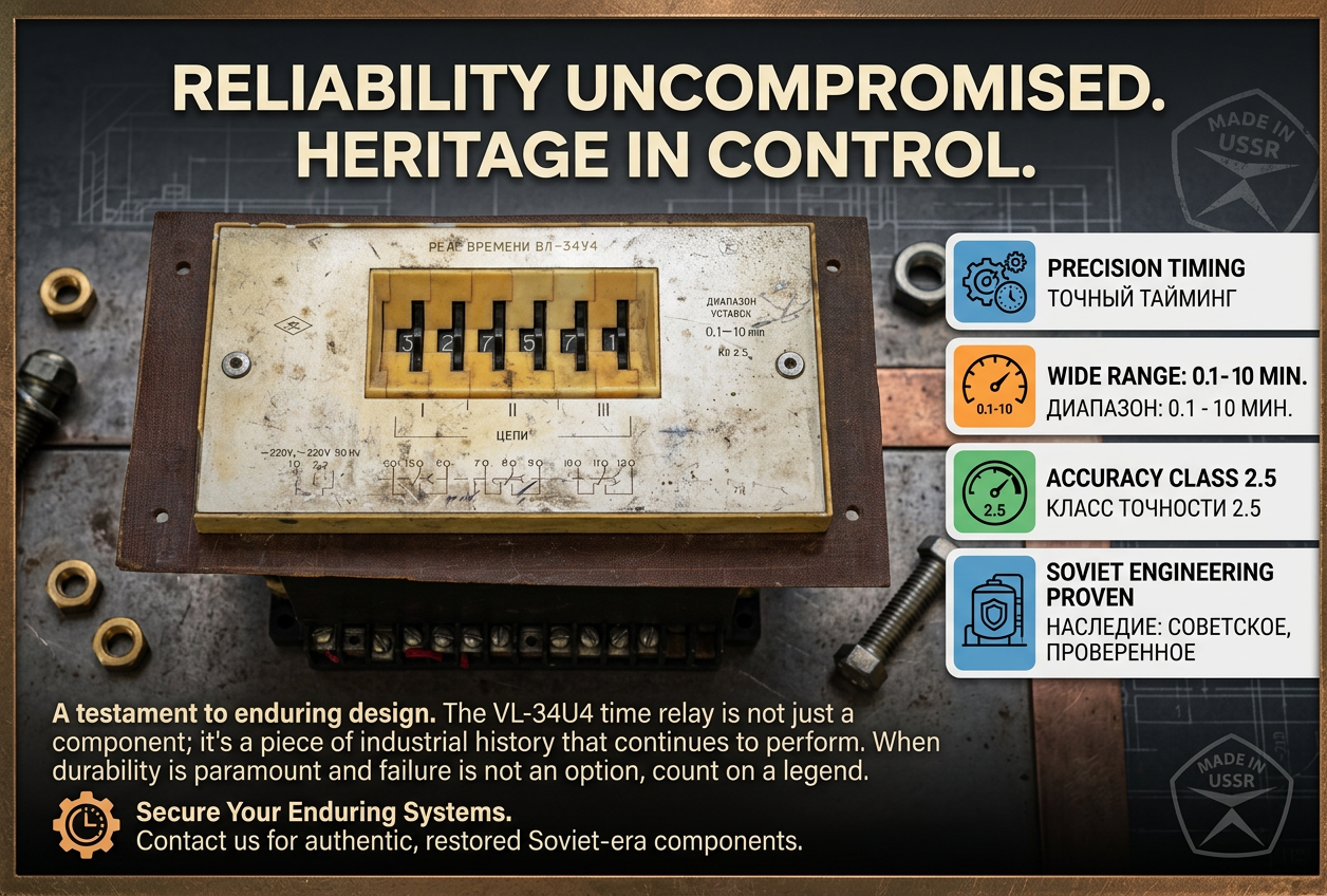
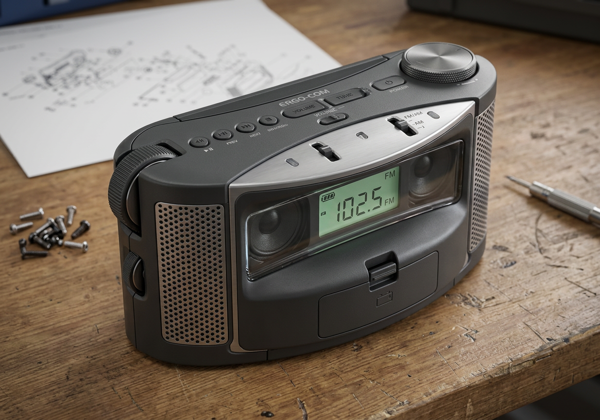
make advertisement for this product

gpt-image-2 (medium)
gpt-image-2 (medium)
gemini-3.1-flash-image-preview (nano-banana-2) [web-search]


I find it difficult to judge which version is better.
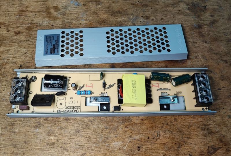
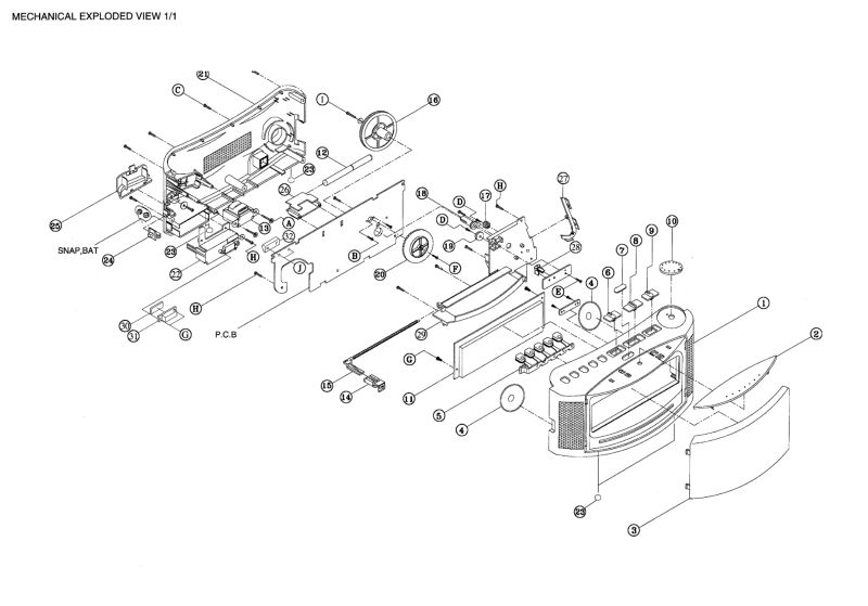
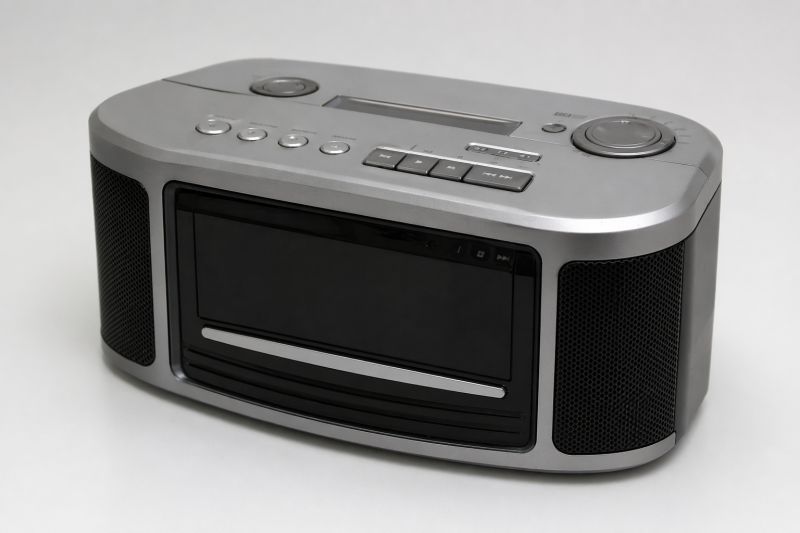
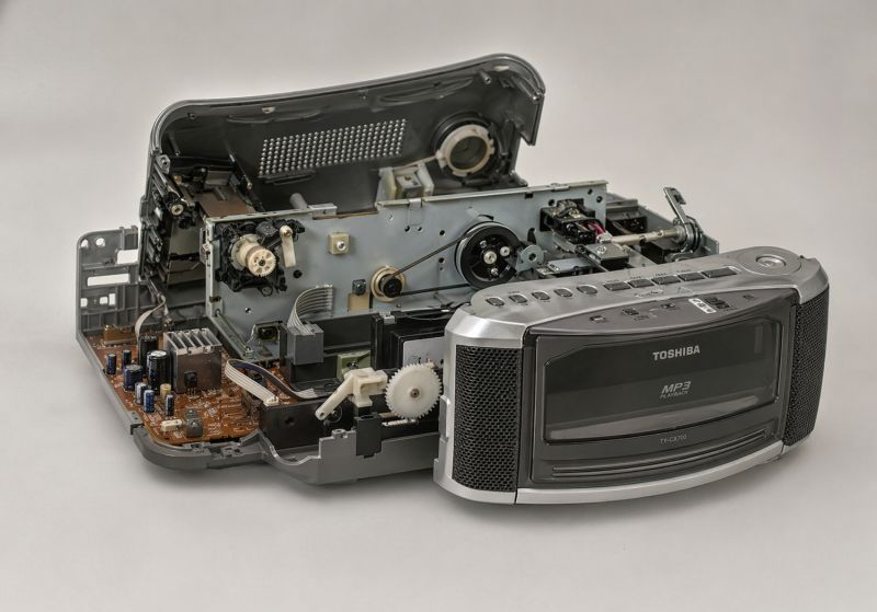
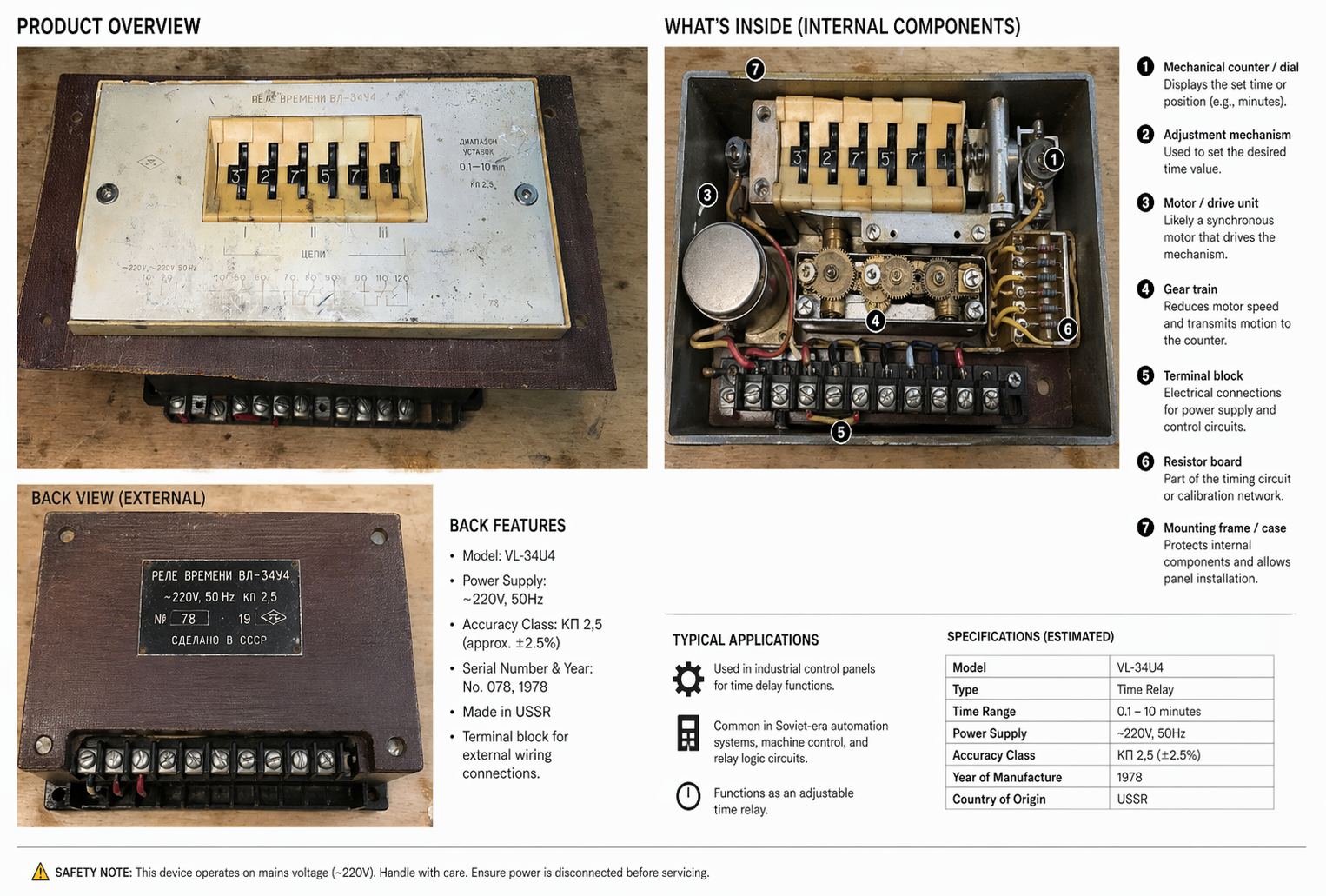
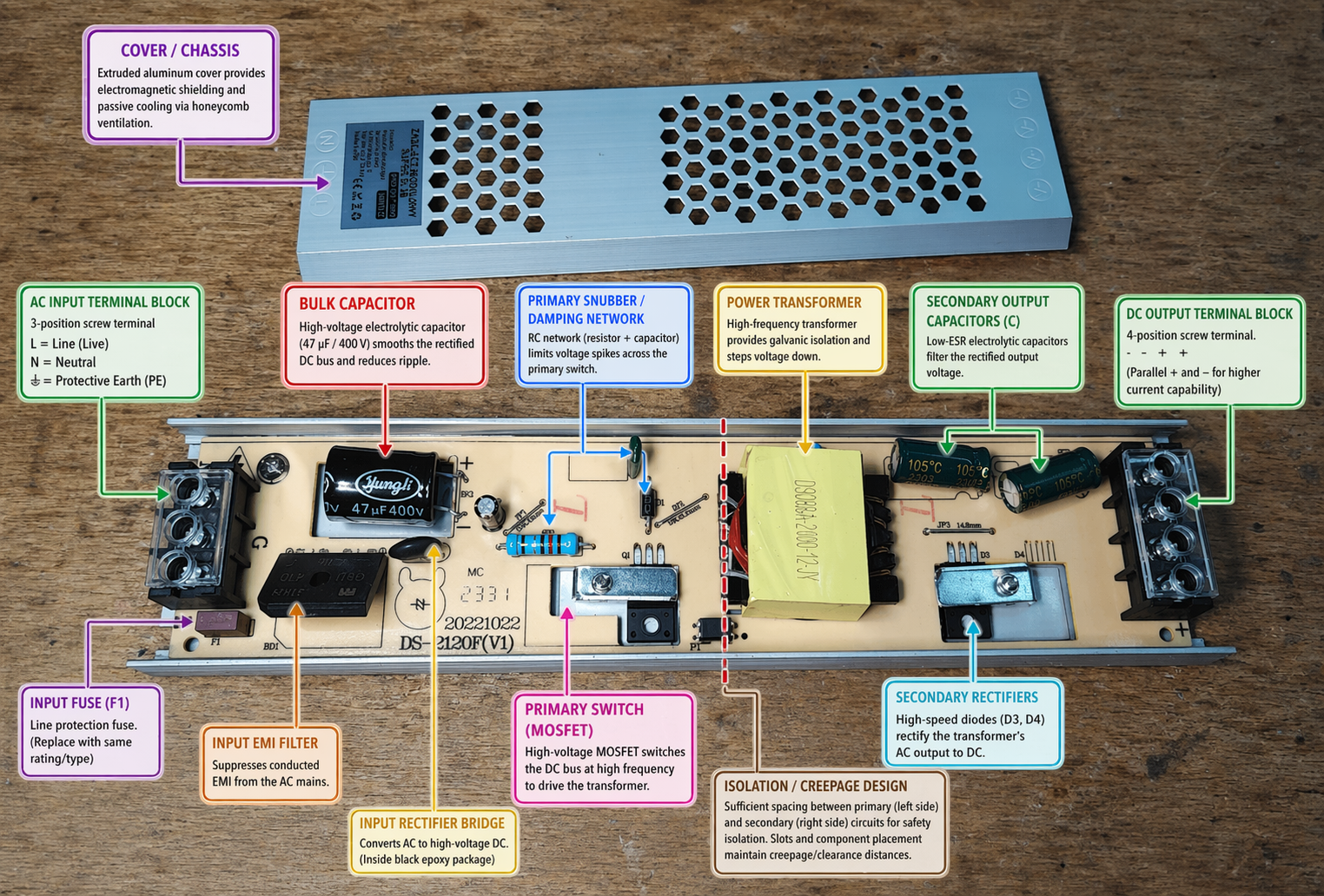
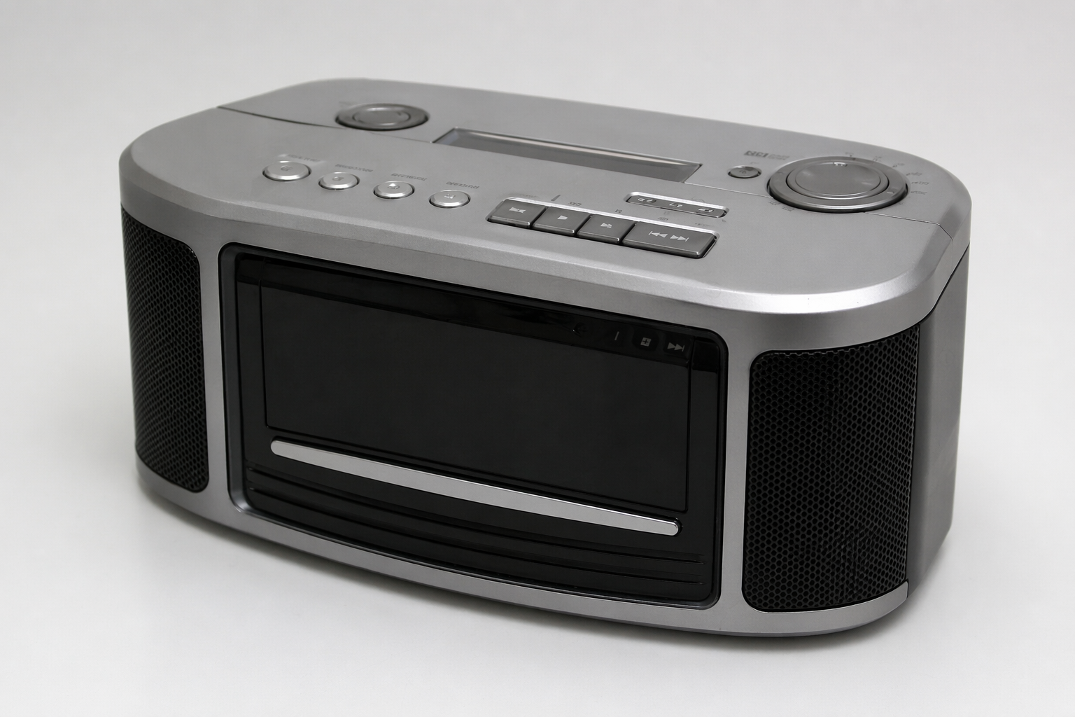
make analysis of this product (what is inside, what is on back)
gpt-image-2 (medium)
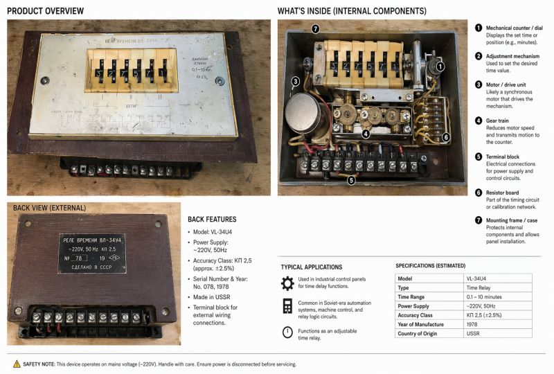

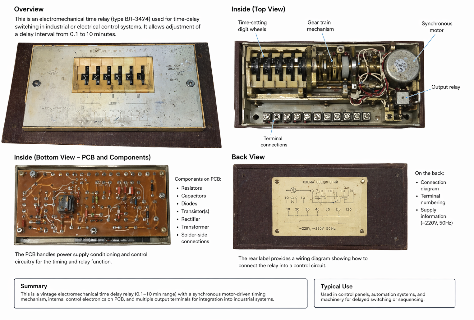
Please annotate sections of this device:
Be detailed and technical
gpt-image-2 (medium)

gemini-3.1-flash-image-preview (nano-banana-2) [web-search]
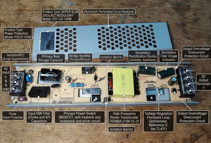
Looks nice, but the errors are fundamental.
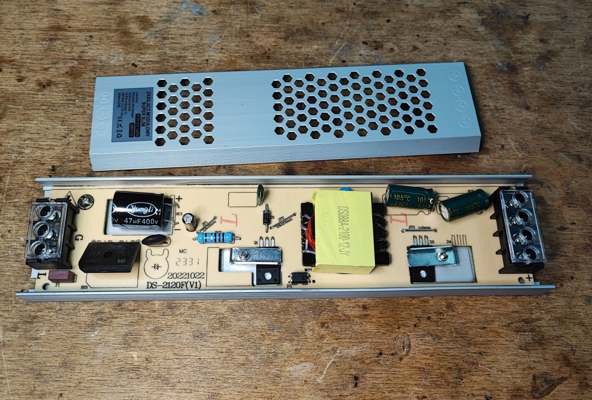
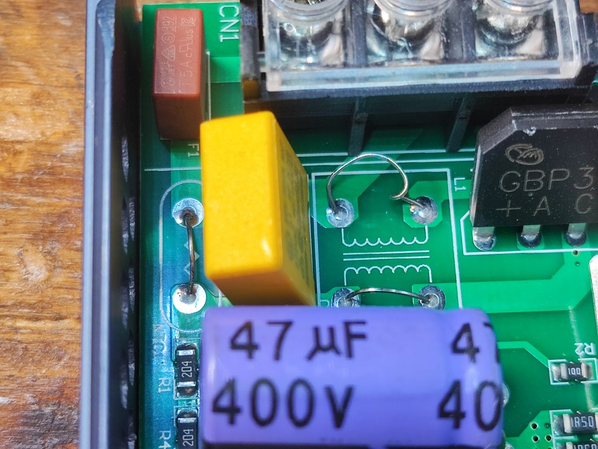
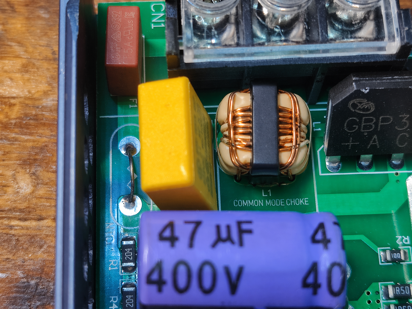
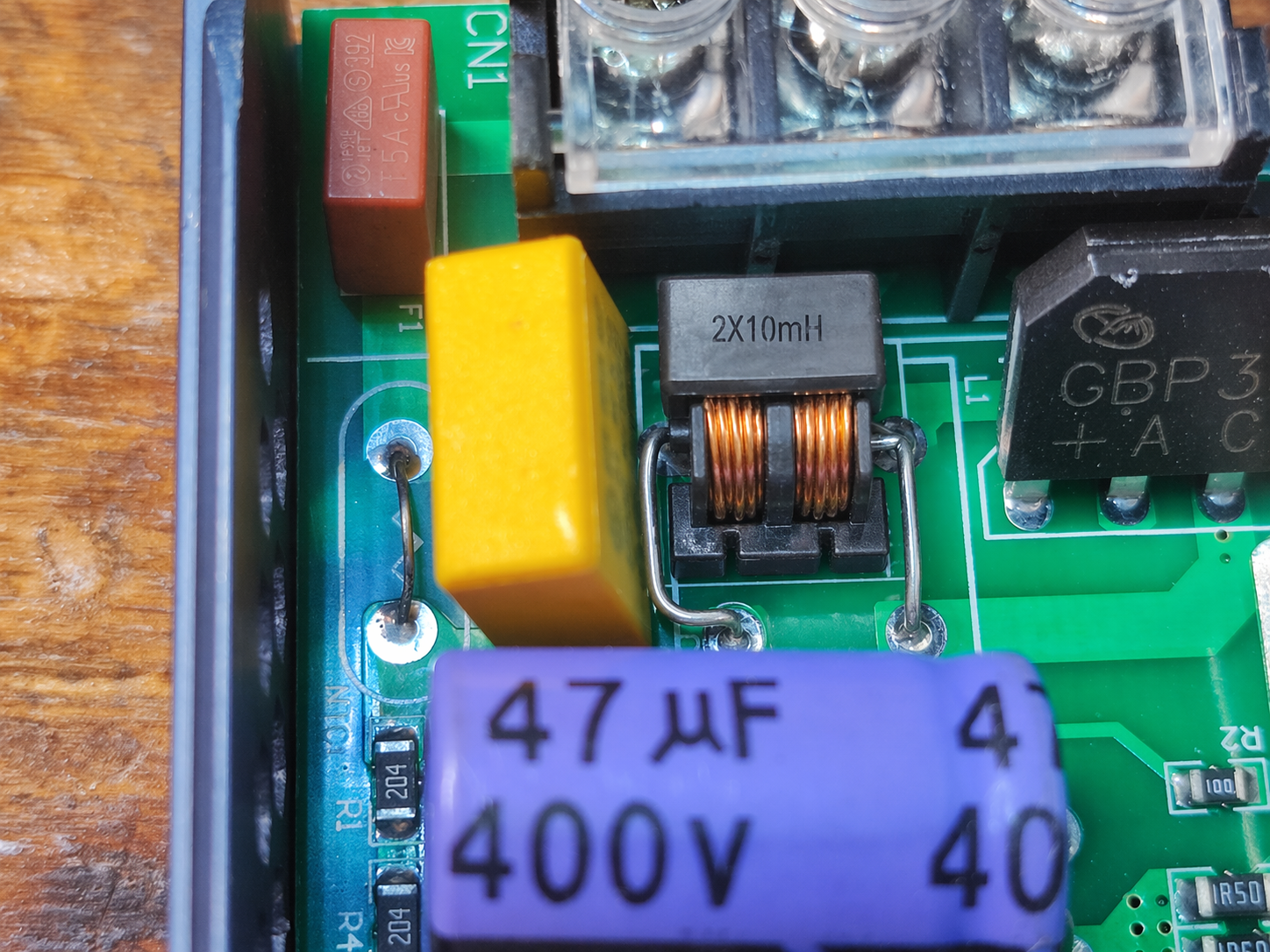
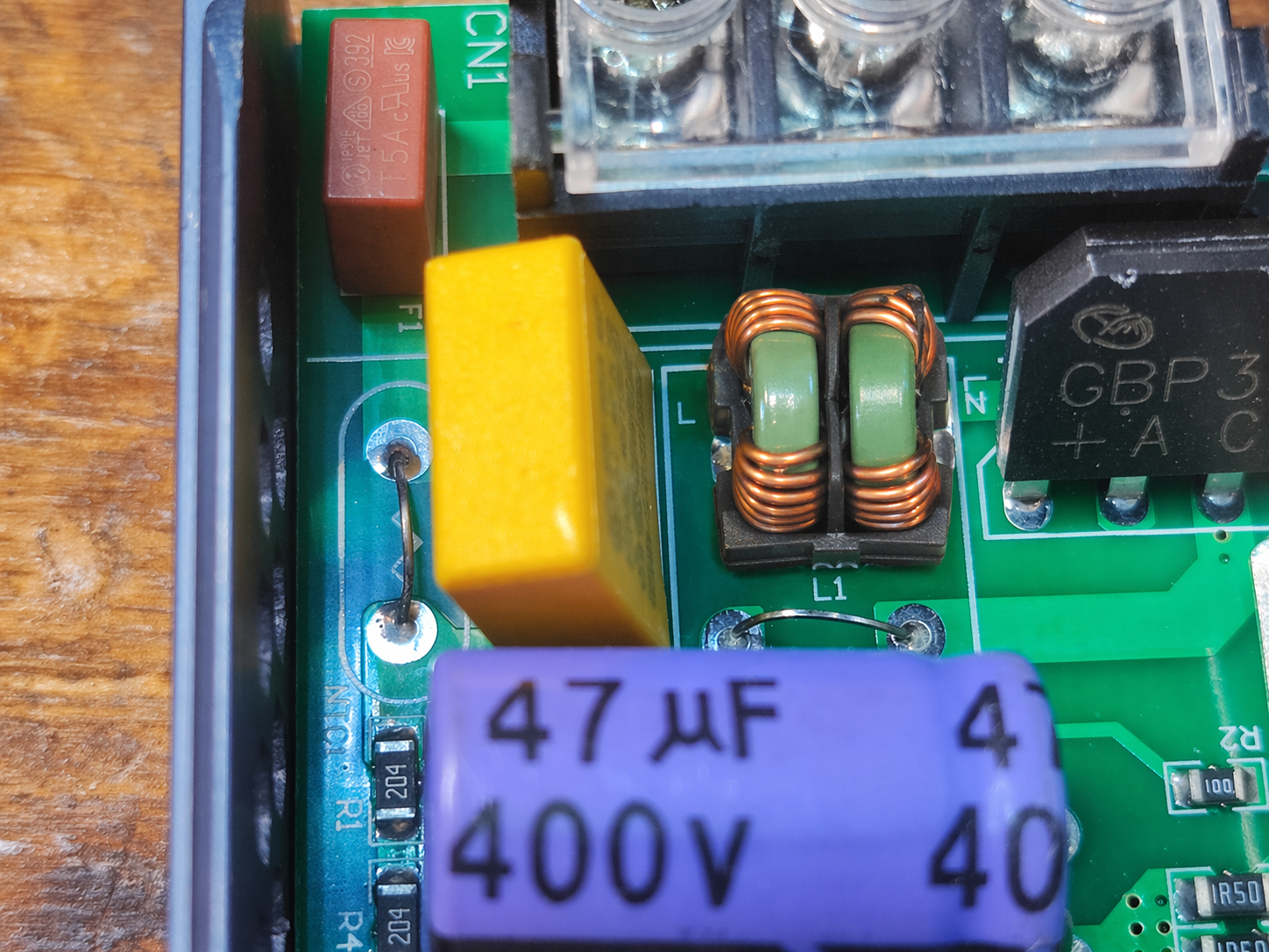
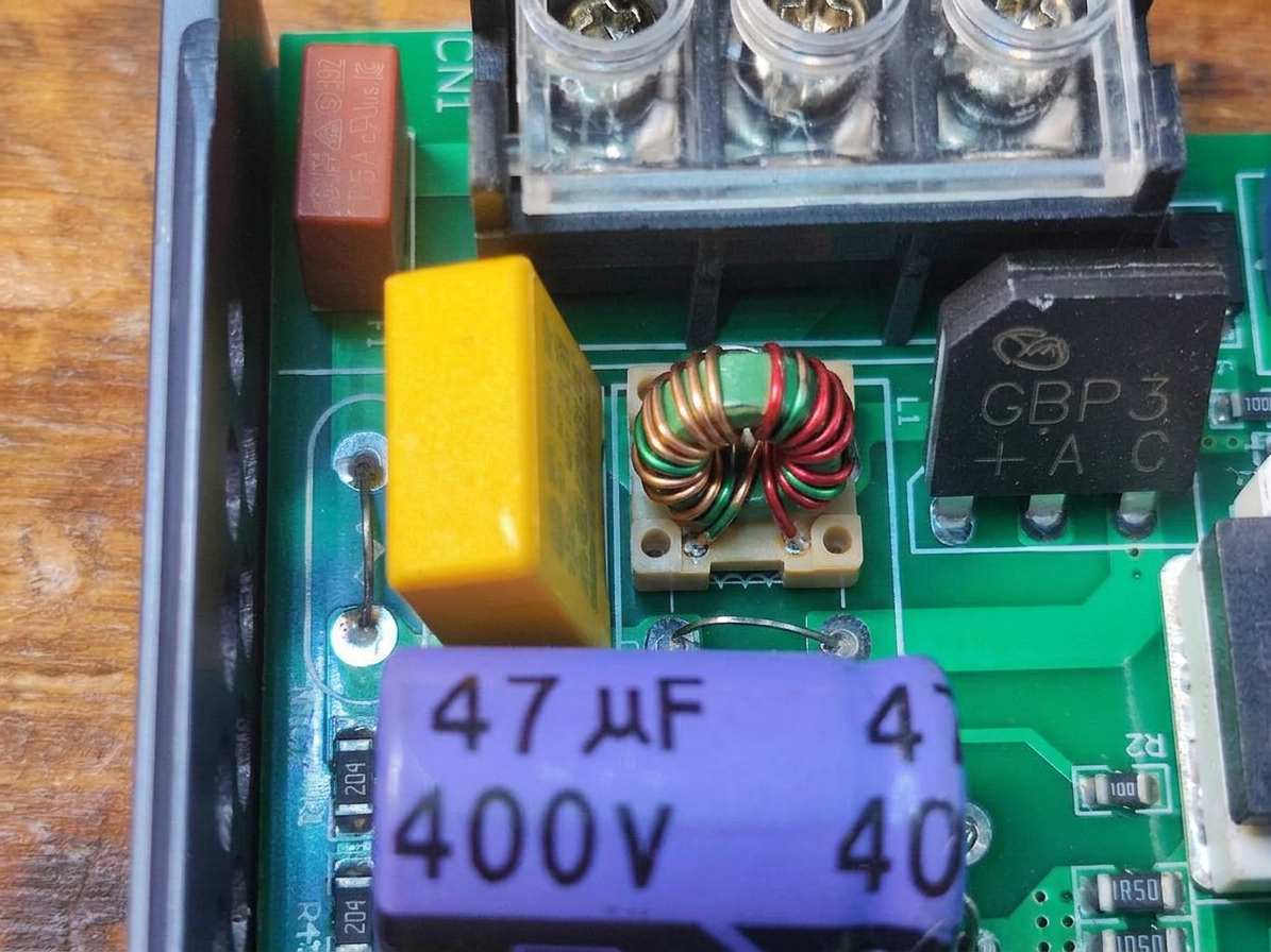
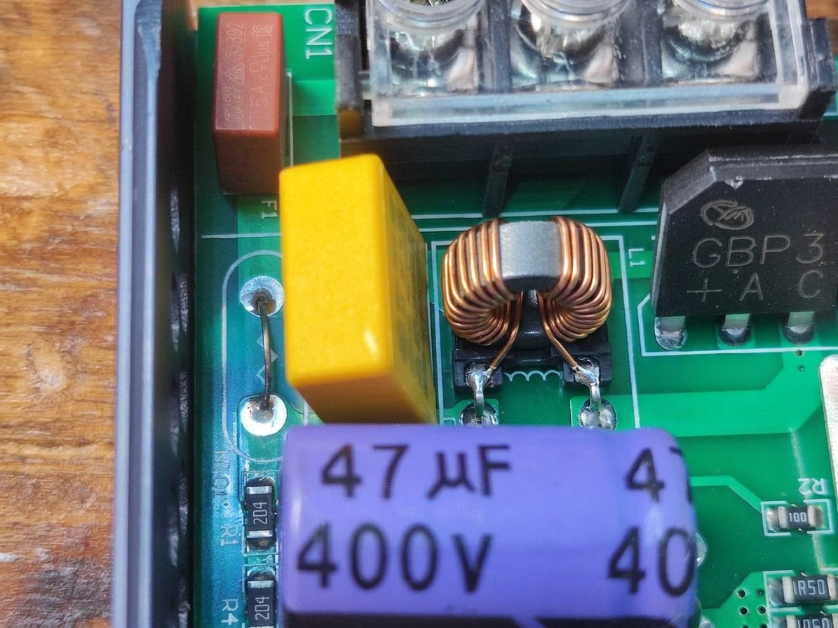
please put a common mode choke in the correct place

gpt-image-2 (medium)

gpt-image-2 (medium)

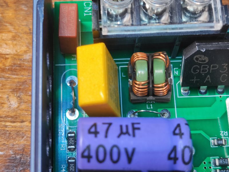
gemini-3.1-flash-image-preview (nano-banana-2) [web-search]

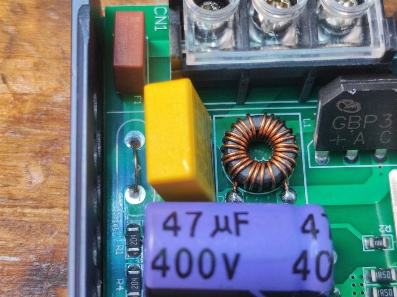

Rather more realistic results from Nano Banana
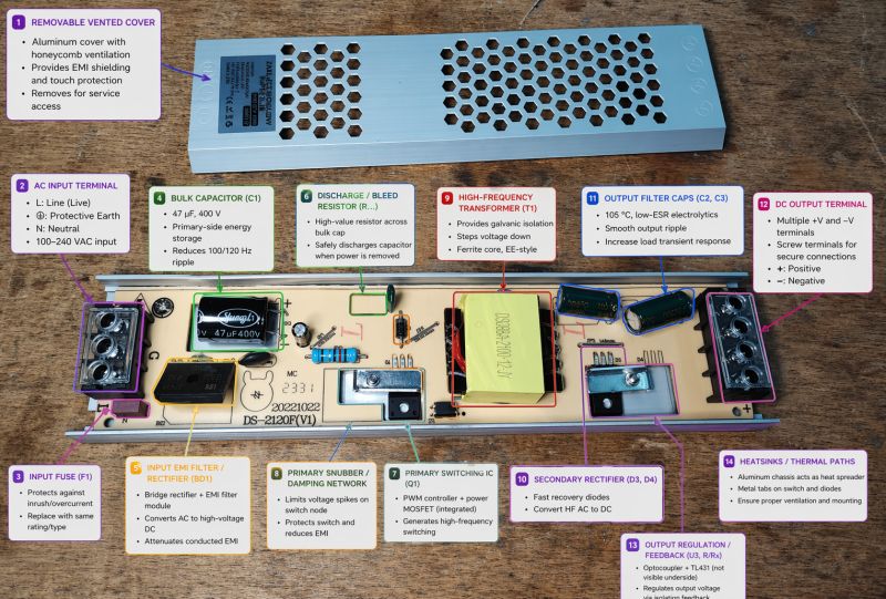
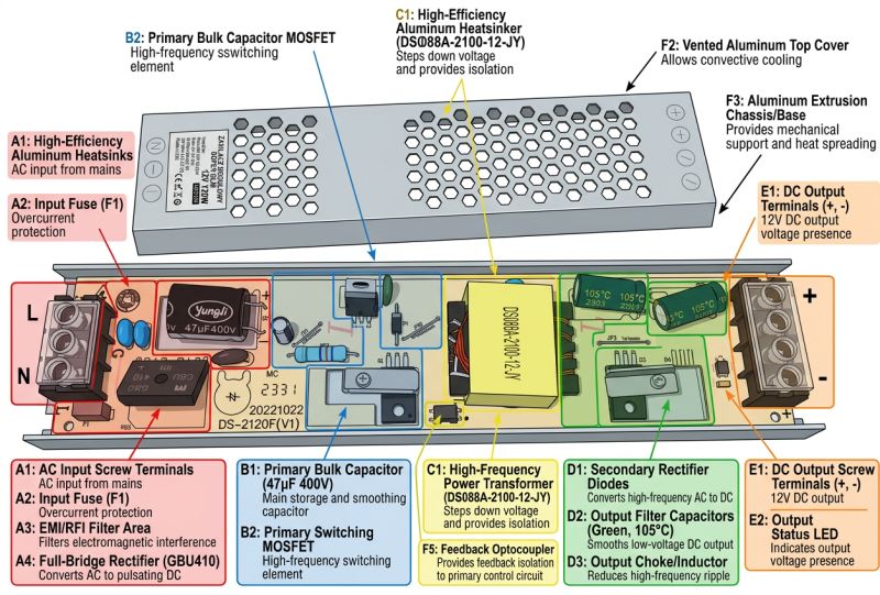
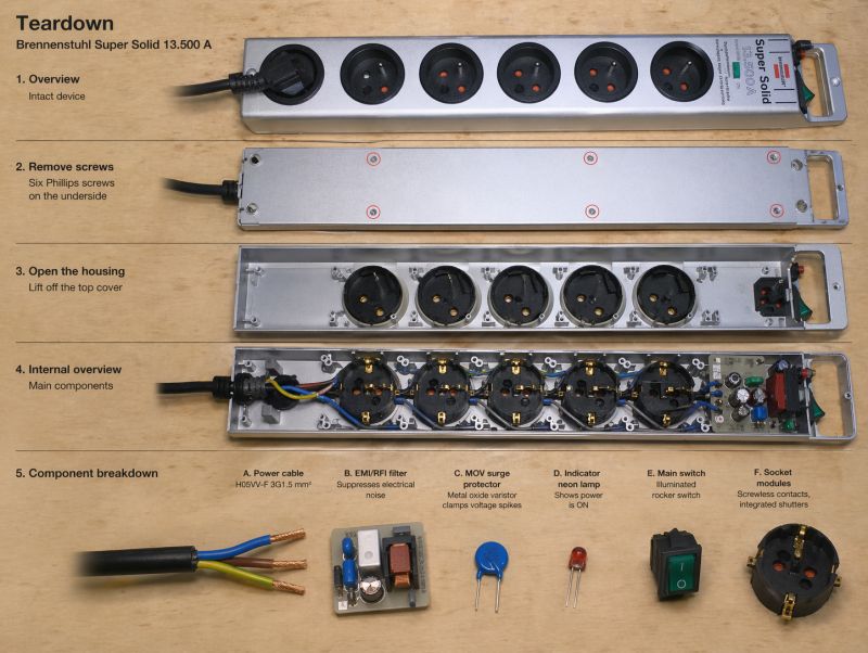
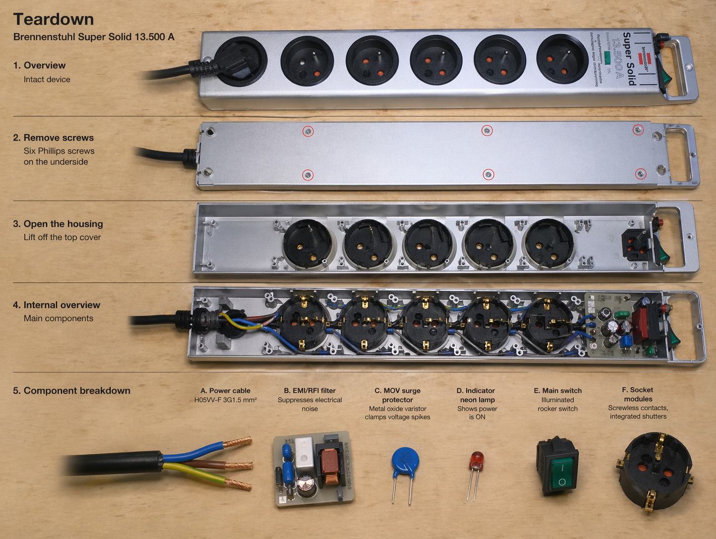
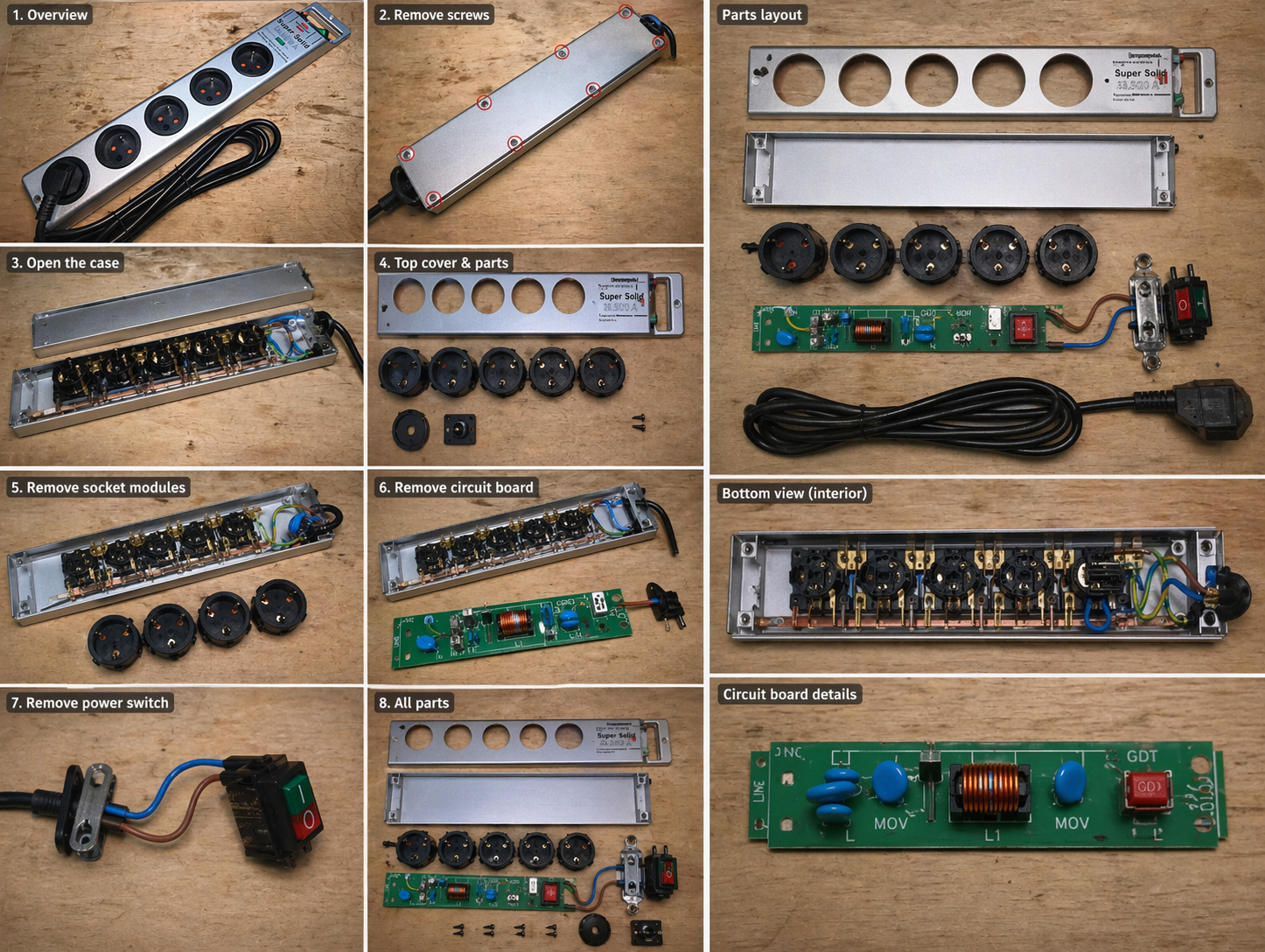
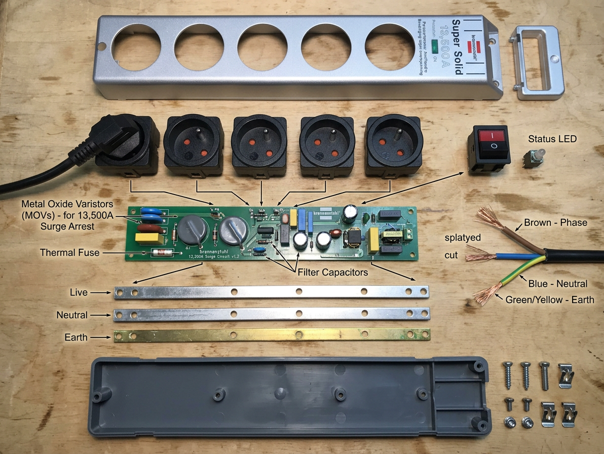
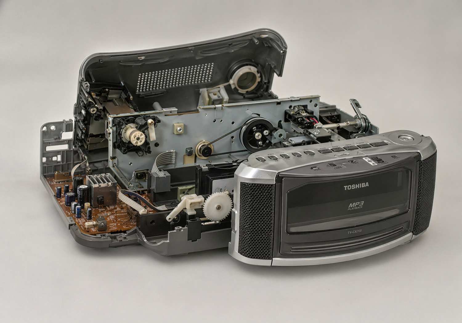
make a teardown of this device
gpt-image-2 (medium)
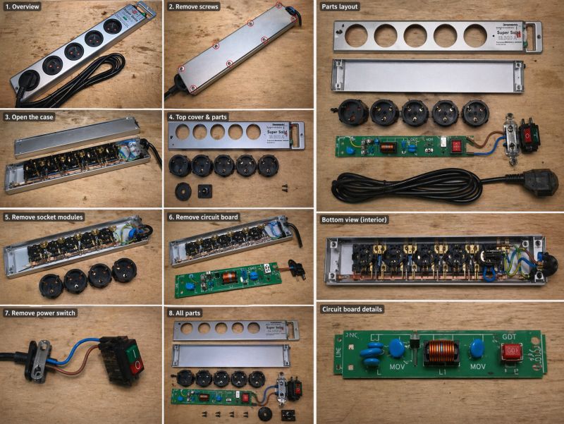
gemini-3.1-flash-image-preview (nano-banana-2) [web-search]


A rather meaningless result, but you can see that GPT-Image 2 prefers infographics and diagrams.
remove usb sockets from the photo
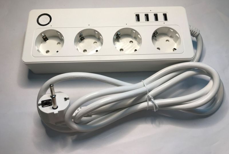
gpt-image-2 (medium)
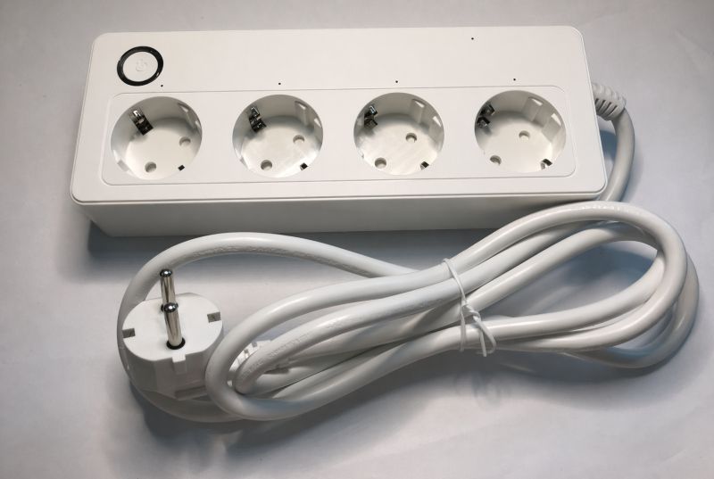

And here's what happened? GPT-Image-2 removed the ground along with the USB...
gemini-3.1-flash-image-preview (nano-banana-2) [web-search]
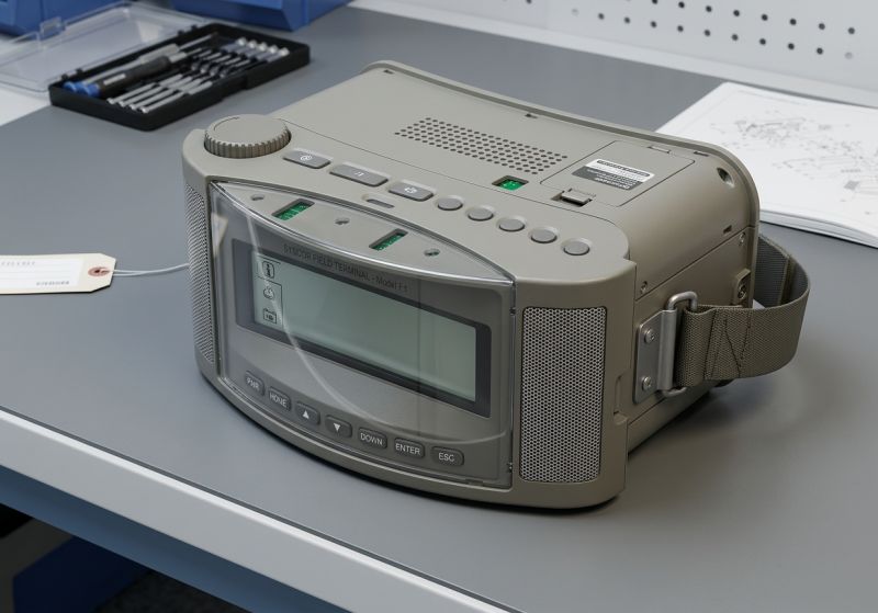
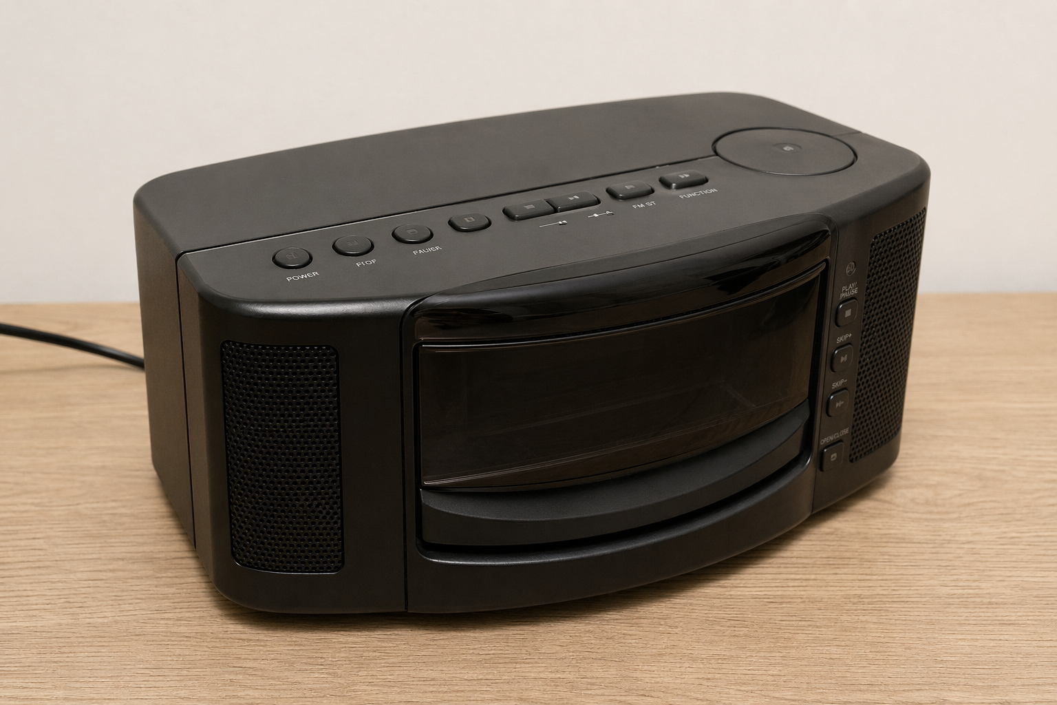
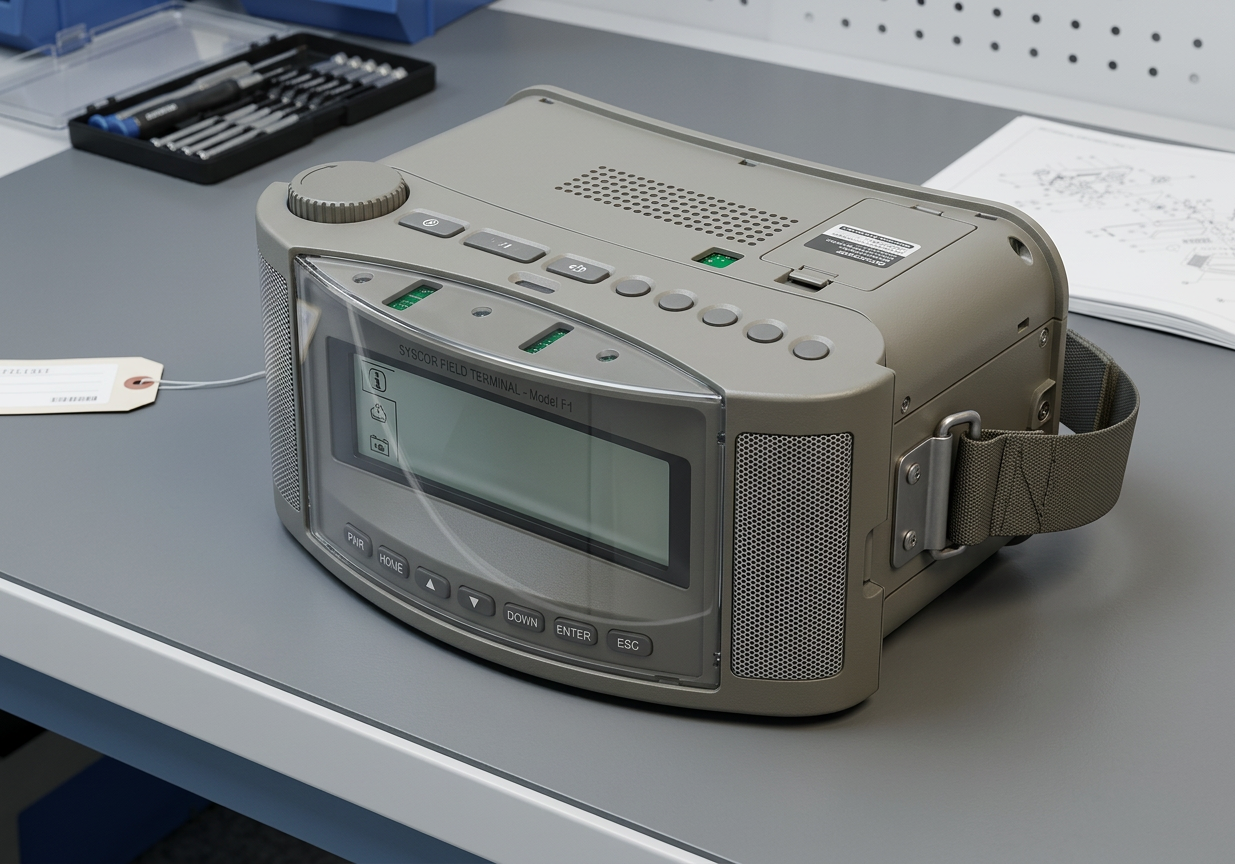
Create a realistic photo showing how would this device look in real life
gpt-image-2 (medium)
gpt-image-2 (medium)
gemini-3.1-flash-image-preview (nano-banana-2) [web-search]

a13b6bb9e
Rather comparatively - once better, once worse.
In summary , it seems that GPT-Image 2 is not at all significantly better than Nano Banana 2 in this context. My impression is that GPT-Image 2 is very fond of generating text, tables, diagrams and infographics, but nevertheless with the field of electronics is still poor. In addition, on the other hand, I saw that GPT-Image 2 does slightly better with object relationships (the needle test on the Arduino) and slightly worse with the electronic components themselves (it does not know what Flash memory is). In summary, based on these tests I would say that GPT-Image 2 has other stronger points than Nano Banana 2, it handles text better, but is not a great step forward overall.
For a full verdict I would still need to test the high version, if one is available. So far I have tested everything on medum.
And what is your opinion? Have you tested GPT-Image 2? 


Comments
Interesting. I expected better results from image 2 One test to try at your leisure - where he gets confused in a diagram or similar, give him a netlist of connections between elements. So that he knows... [Read more]
I was also just thinking of trying to write in the prompt what to connect and how to connect, as I will then generate. I'll try it at my leisure. I'll try to redo this example "draw detailed schematic... [Read more]
All in all, if someone asked me about flash memory, I wouldn't know which specific model or enclosure they were referring too. And yet in professional design you have to be accurate. This is what AI... [Read more]
Just in a situation like there on the PCB, the choice is quite obvious. What's more, the Nano Banana 2 copes with it, and recognises well the distinctive casing and markings of a chip that is common even... [Read more]
I don't know, for me such a choice is not obvious and it is difficult to judge on this basis whether one is better than the other. I'll give an example like this: I send the first messenger to get rice... [Read more]
But it would be interesting to see how he would handle the netlist. I found one case in point. https://github.com/nturley/netlistsvg Schema original created with JSON: https://obrazki.elektroda.pl/5230585500_1777037602_bigthumb.jpg... [Read more]
Yes. I asked it to draw me a Beken CB3S https://obrazki.elektroda.pl/6193131800_1777127613_thumb.jpg 😂 Added after 1 [minutes]: Maybe I should watermark that image with a warning in the event... [Read more]
In terms of usability, of course, the AI's graphical abilities alone are at TOP level when it comes to comparing with human capabilities (we are talking about a normal user and not a graphic artist with... [Read more]
It would be nice if such a generator was created for schematics, returning a netlist, it would have to be trained on all the datasheets and schematics in the world, service manuals anyone has ever produced.... [Read more]
There are already such tools ( ProtoFlow, Circ AI, Skimatly, etc... ) - I have tried them, but with their results vary. This is definitely not the level that we get with e.g.: Opus 4.7 when programming. Not... [Read more]
Hm... well how about simulations? That is, the model (randomly?) connects some elements (builds a schematic) and simulates them in some SPICE and observes the output, kind of analogous to how robots learn... [Read more]
Here I have converted the diagram from ASCII: https://www.elektroda.pl/rtvforum/topic4172412.html#21893068 It even came out. [Read more]
Someone seems to be "testing" as well: Request for help in verifying the fan switching circuit [Read more]