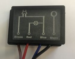
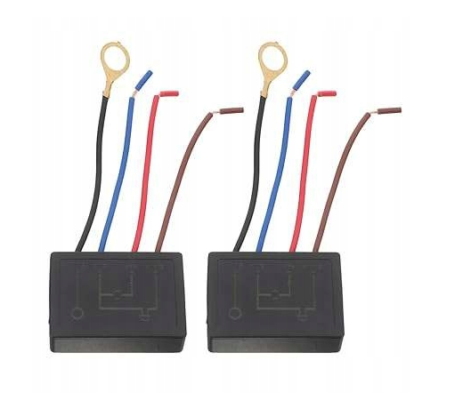
Today, another curiosity from online shops - a touch dimmer controller module for a bedside lamp. The whole thing works with classic incandescent bulbs and with LEDs designed for dimmers. The principle of operation is simple - one of the wires is connected to the metal housing of the lamp and it fulfils the role of a touch button, whose separate presses switch successive brightness levels - low, medium, high, and the lamp's off state.
I have shown a similar gadget before:
Touch bedside lamp with three brightness levels - interior, module, DIY
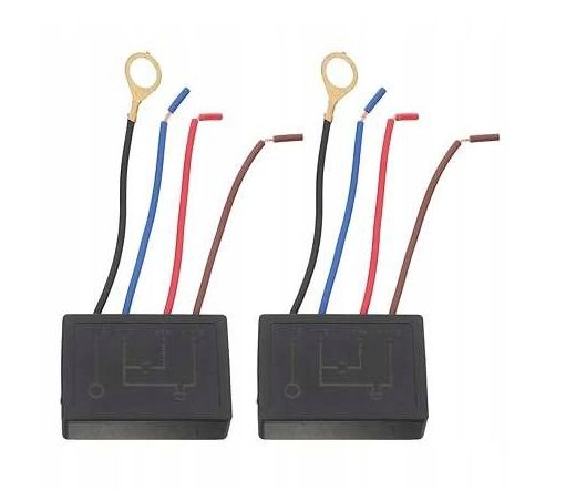
Let's start with the price. I was able to buy two of these modules from a Polish online shop for £25, but you still had to add shipping.
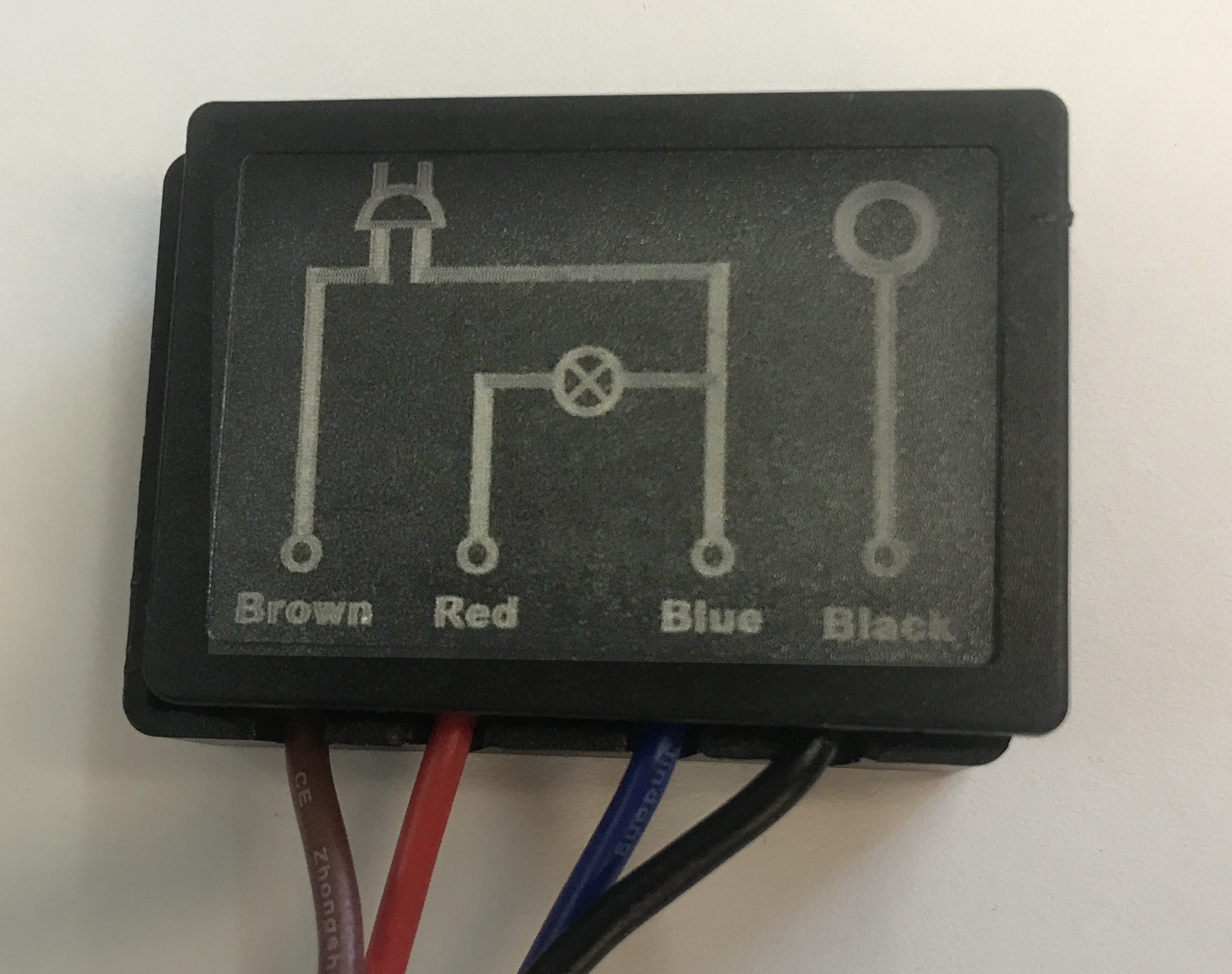
Assembly of the unit is very simple. It is illustrated by the diagram on the housing.
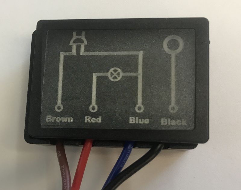
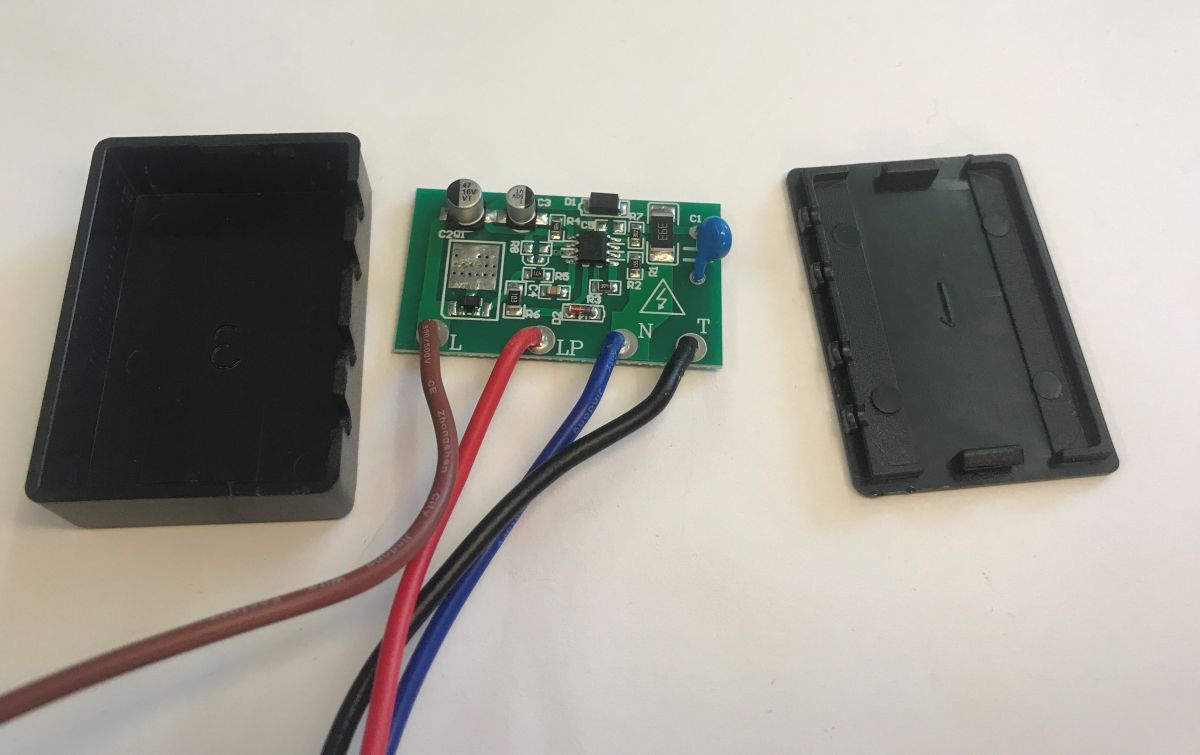
The black cable connects to the lamp housing, which is the touch button. However, it is time to look inside:
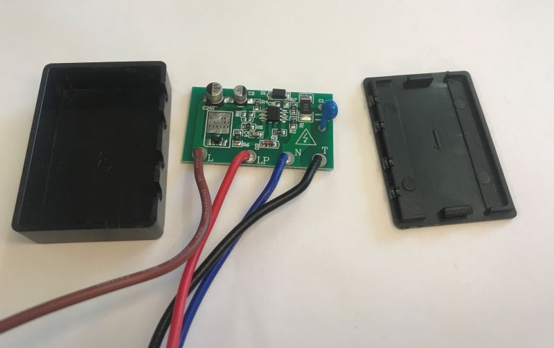
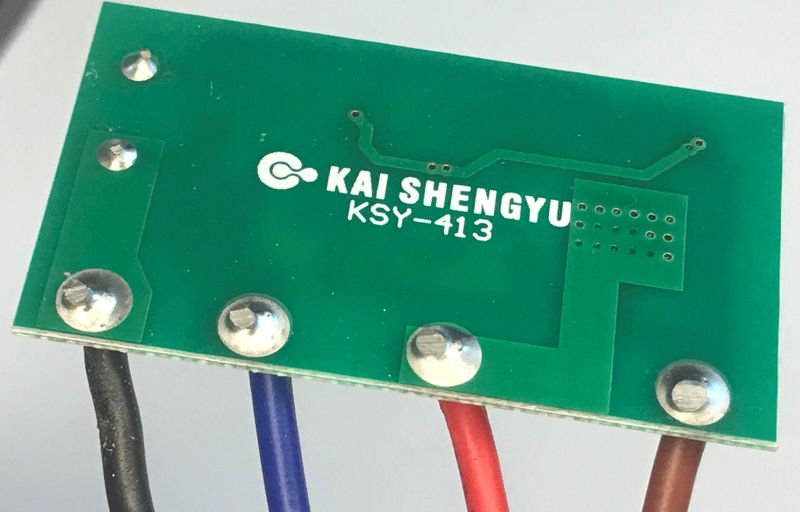
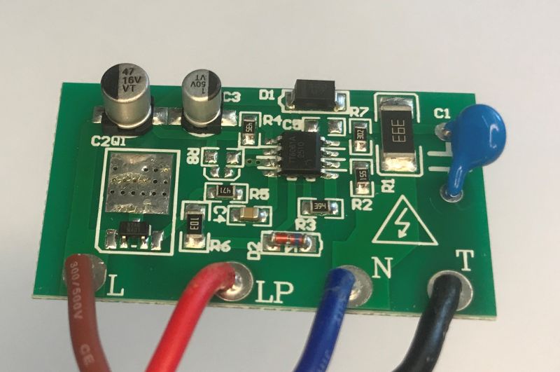
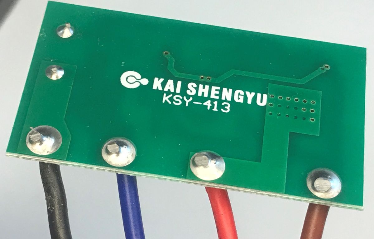
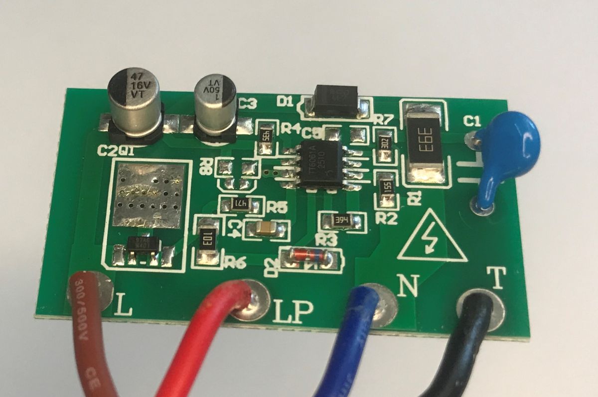
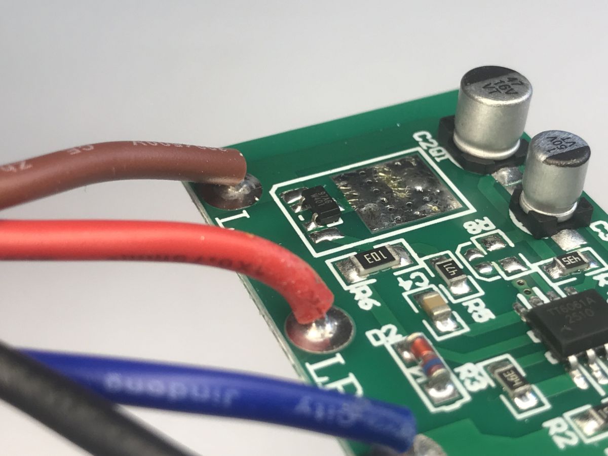
Inside is a single double-sided board, almost entirely based on surface mount - only the CY capacitor is mounted in a through-hole manner.
The module is based on the TT6061 chip:
A 97A6 W401 triac, here very tiny and surface mounted, is used to cut the 230 V line. The board was also designed with a larger triac in mind, as you can see the manufacturer is optimising costs:
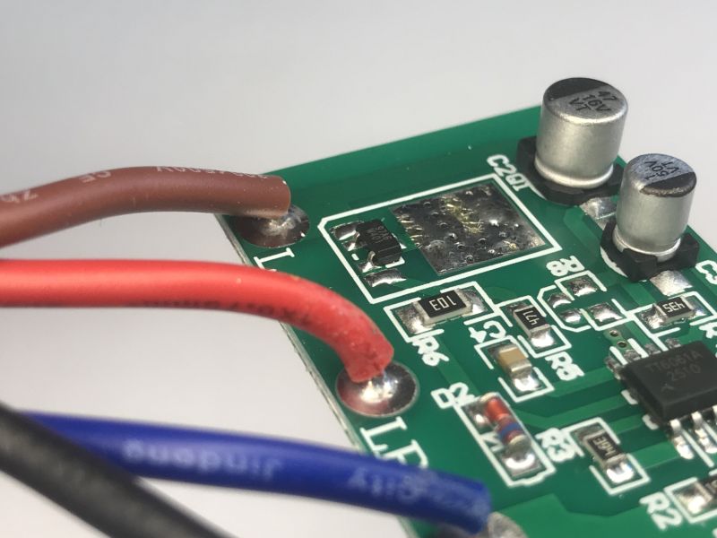
Could it be a MAC97A6 or similar? 600 mA, 400 V.
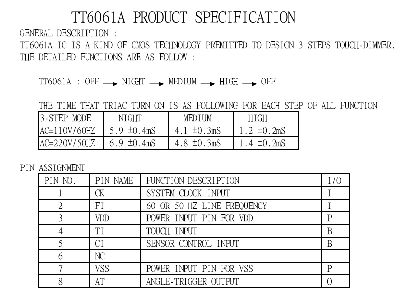
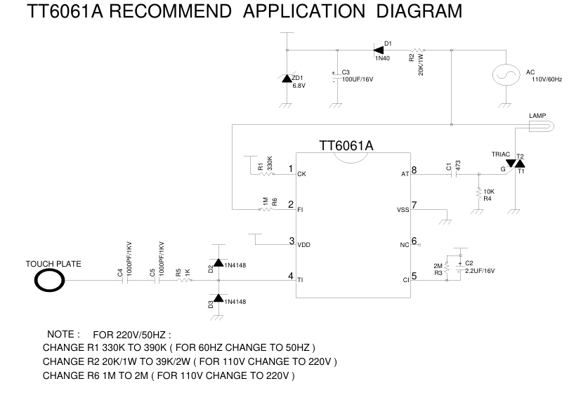
Finally, most importantly, the TT6061 documentation and application note:
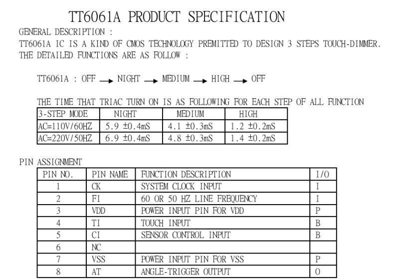
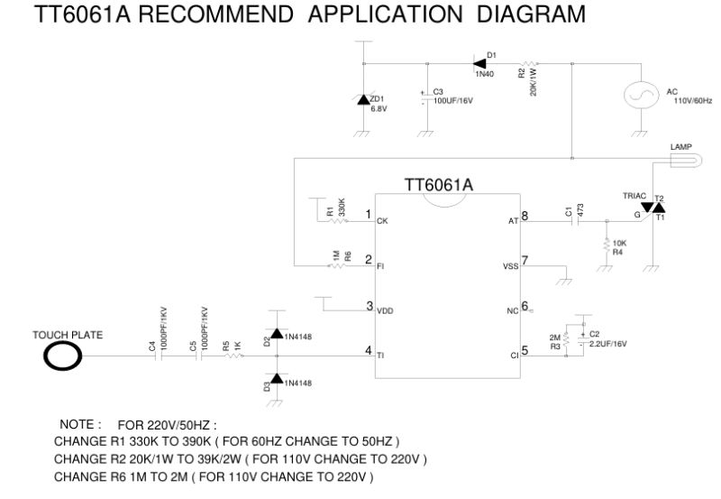
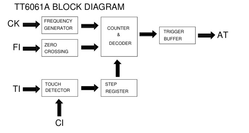
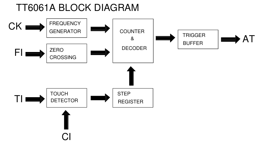
The circuit in this version dates from 2009. It requires a small number of components to work. It can operate on 110 and 220 V, although each voltage needs separate resistor values R1, R2 and R6. Switching is realised with an external triac; the manufacturer was not tempted to integrate the triac in the housing together with the controller. Block diagram:
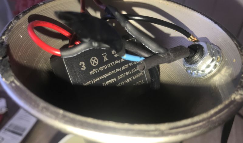
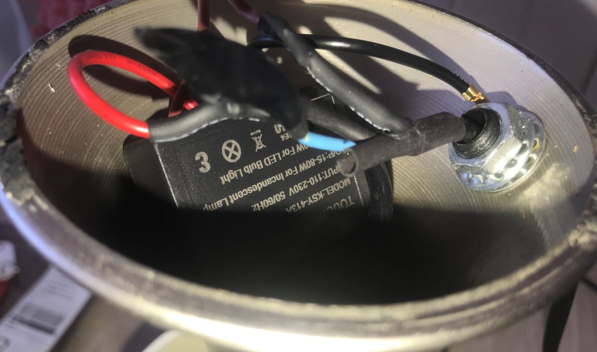
The module is already mounted in the lamp and fits well there.
 In summary
 , here we have a simple controller that detects the touch of the lamp housing and controls the triac in such a way that several brightness levels are achieved. The black wire connected to the metal lamp housing acts as a sensor electrode - a touch causes a change in capacitance, which the TT6061 circuit interprets as a control pulse and switches the next mode of operation.
The brightness is controlled by controlling the moment the triac is switched on in each half-period of the mains voltage. For the highest brightness, the triac is switched on from the beginning of the half-period, for medium and low brightness it is switched on with an appropriate delay, so that a smaller part of the sine wave reaches the bulb. In the off state, the circuit simply does not apply pulses to the gate of the triac.
Once switched on, the triac conducts until the current falls below the holding current, which in an AC network occurs naturally when the voltage passes zero. In the next half period, the circuit again decides whether and when to give an ignition pulse - depending on the selected brightness level.
The whole thing is therefore a classic phase dimmer with a simple touch sensor and four operating states: off, low, medium and high brightness levels.
The device is simple, although also susceptible to damage, which I have already experienced with a neighbour's lamp - if someone screws an LED lamp in there, one with a capacitor at the input, the current pulse drawn by the capacitor at a lower brightness level will sooner or later damage the triac, and the module will have to be repaired or replaced.
Another issue is the question of the safety of such a gadget - we are protected here by a capacitor (there are two in the diagram) of the appropriate (I hope) class, similar to those connecting the primary to the secondary in a switching power supply.
Does such a control make sense? I leave the decision to you. Do you use such lights? How do you rate this type of solution? 







Comments
All operator safety is based on capacitor C1. The application note clearly indicates that there should be 2 capacitors in series. Here they have saved money and given 1. I would rather not rely on such... [Read more]
Something will happen/change as well as the protective conductor screws into the housing ? [Read more]
I see a different situation here: this is a universal board and allows at least two different power triacs to be mounted and in two different resulting housings. [Read more]
It will not work. Man is for this device a parallel connected resistance and reactance connected to earth (as in a neon tester). If you ground this it's like adding a 0R resistor in parallel. The circuit... [Read more]
Phase control and zero filters, one would expect none of these lights to meet the standards :) [Read more]