






A giant screen from days gone by – the interior of a 29-inch Sony Trinitron KV-29X5K CRT television
TL;DR
- A 29-inch Sony Trinitron KV-29X5K CRT television is opened and photographed inside, showing its layout, tube, boards, speakers, and service documentation.
- The set uses a Super Trinitron tube with 110-degree deflection, a separate standby converter, a STR-F6654 main supply, and a 2SD2539 horizontal output transistor.
- Rear and front connectivity includes two SCART sockets, RGB, S-Video, composite input, RCA audio, and a headphone jack, alongside 2×20 W speakers.
- The service manual exposes exploded views, circuit schematics, pinouts, waveforms, and voltage points, making repair-oriented disassembly much easier than modern TV documentation.
AI summary based on the discussion. May contain errors.
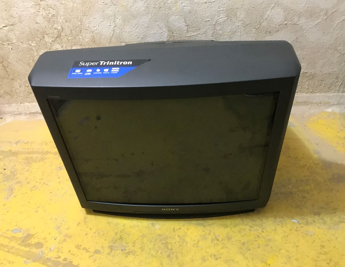
Do you remember cathode-ray tube televisions? Here is a look at the Sony Trinitron set, which stands out with its huge 29-inch screen, two built-in 20-watt speakers and a weight of well over 40 kilograms. Full specifications below:
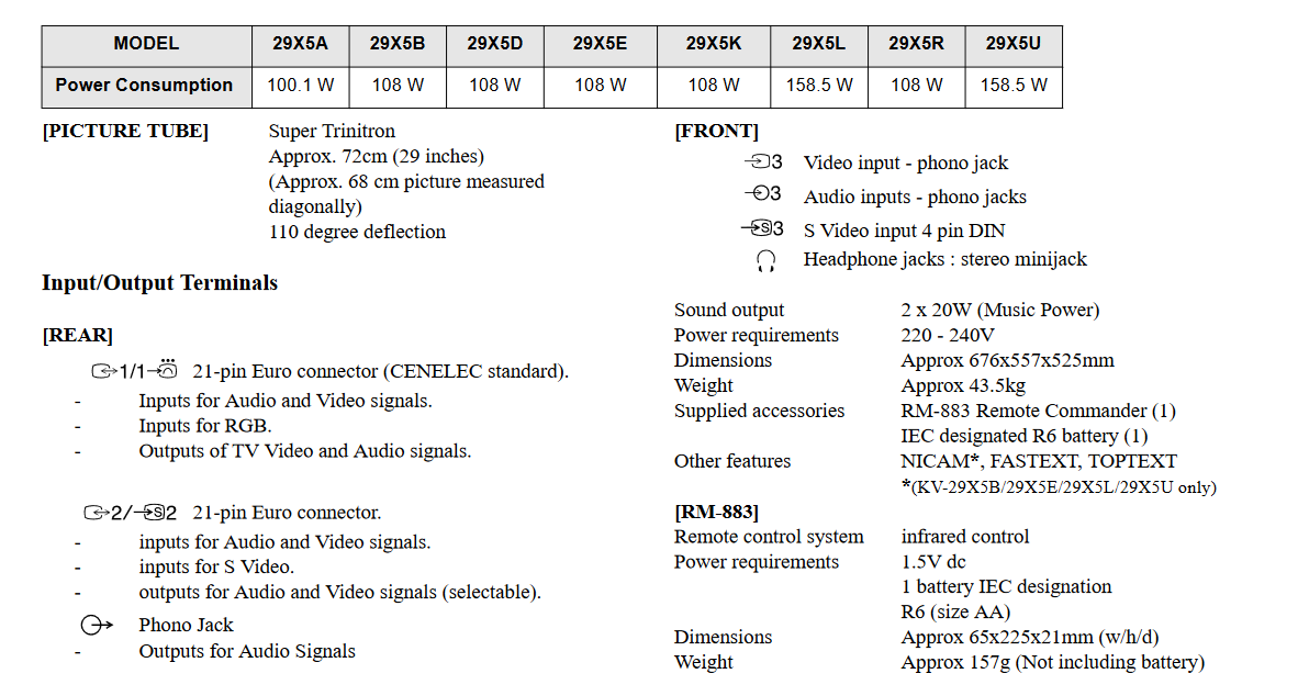
The KV-29X5K has a power consumption of 108 W and is based on a Super Trinitron picture tube with a visible diagonal of approx. 68 cm (the beam deflection angle is 110 degrees). The television is equipped with a wide range of connectors: at the rear it has two SCART sockets (supporting RGB and S-Video), whilst at the front there is a composite (cinch) input, an S-Video input and a headphone socket. The package is rounded off by a built-in 2x20 W sound system. Its dimensions are also impressive – with a depth of over 52 cm, this set weighs as much as 43.5 kg.
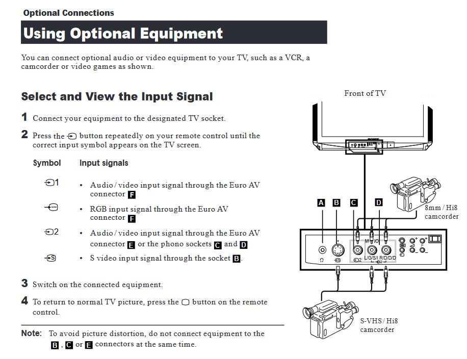
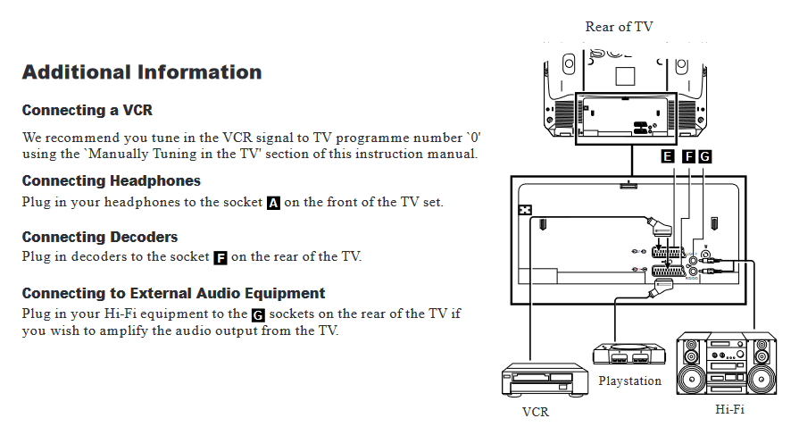
The manual attached to this thread doesn’t just cover user-related matters – it also contains information for service technicians, including instructions on how to dismantle the television. What caught my attention there was the option to secure the circuit board in a service position. It’s clear that the whole unit was designed with repairs in mind.
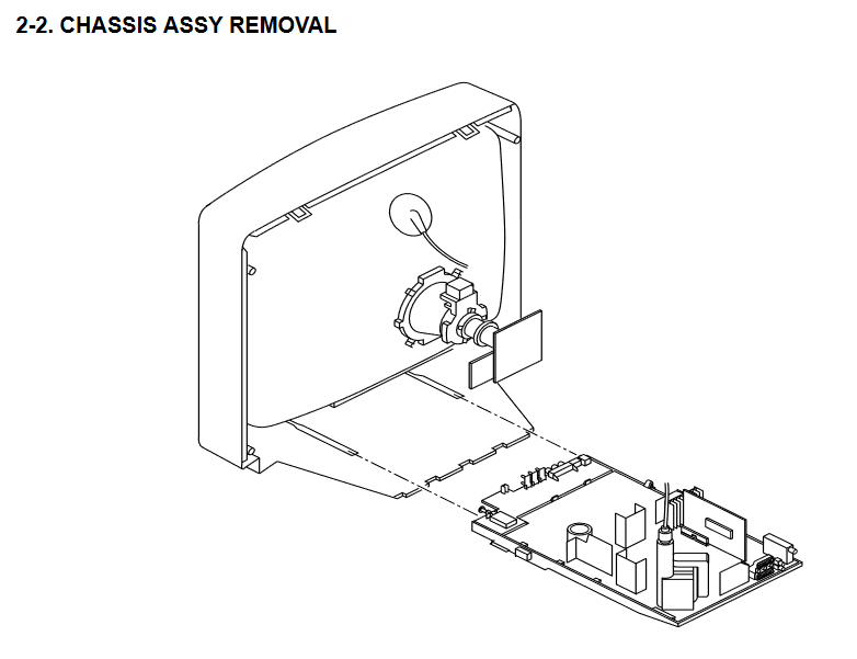
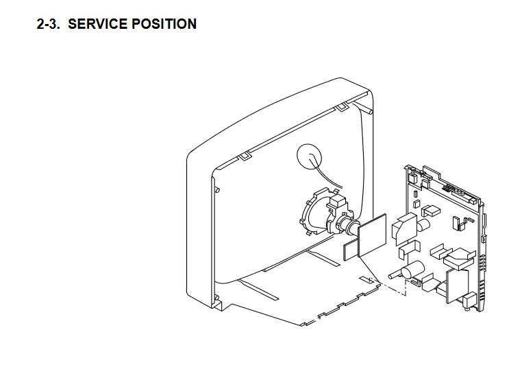
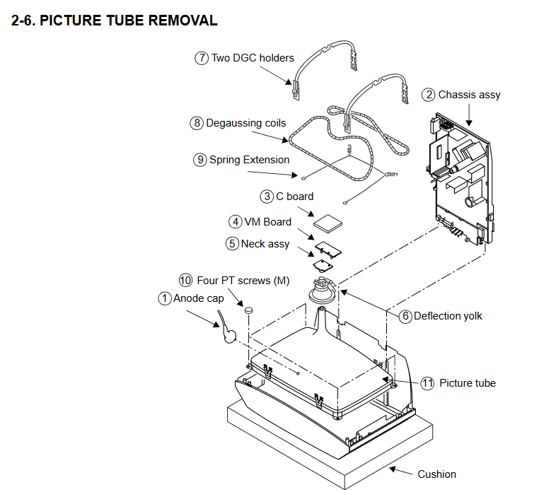
The disassembly of the CRT is also described. WARNING: The interior of a CRT television is dangerous! The cathode-ray tube acts as a capacitor and a dangerous high voltage (of the order of 25–30 kV) may remain in the vicinity of the ‘suction cup’ (anode) for a very long time after the mains power has been disconnected. Furthermore, striking or breaking the neck of the picture tube risks a dangerous implosion. Please exercise caution when carrying out any experiments with this type of equipment and do so at your own risk.
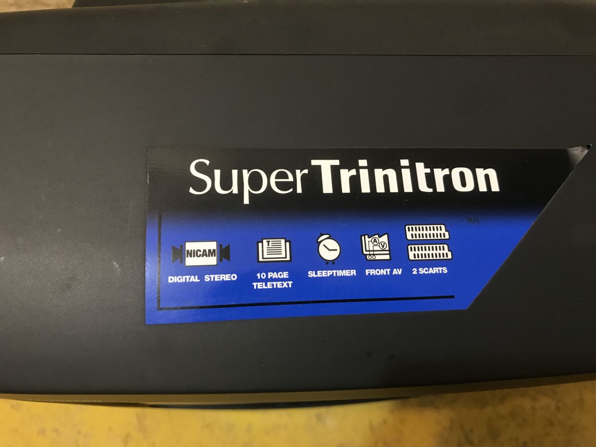
It looked very similar in my case. Incidentally, you may notice the sticker advertising the features of this set, namely the NICAM standard (digital stereo), 10-page teletext, a sleep timer, AV sockets on the front and two SCART sockets on the back.
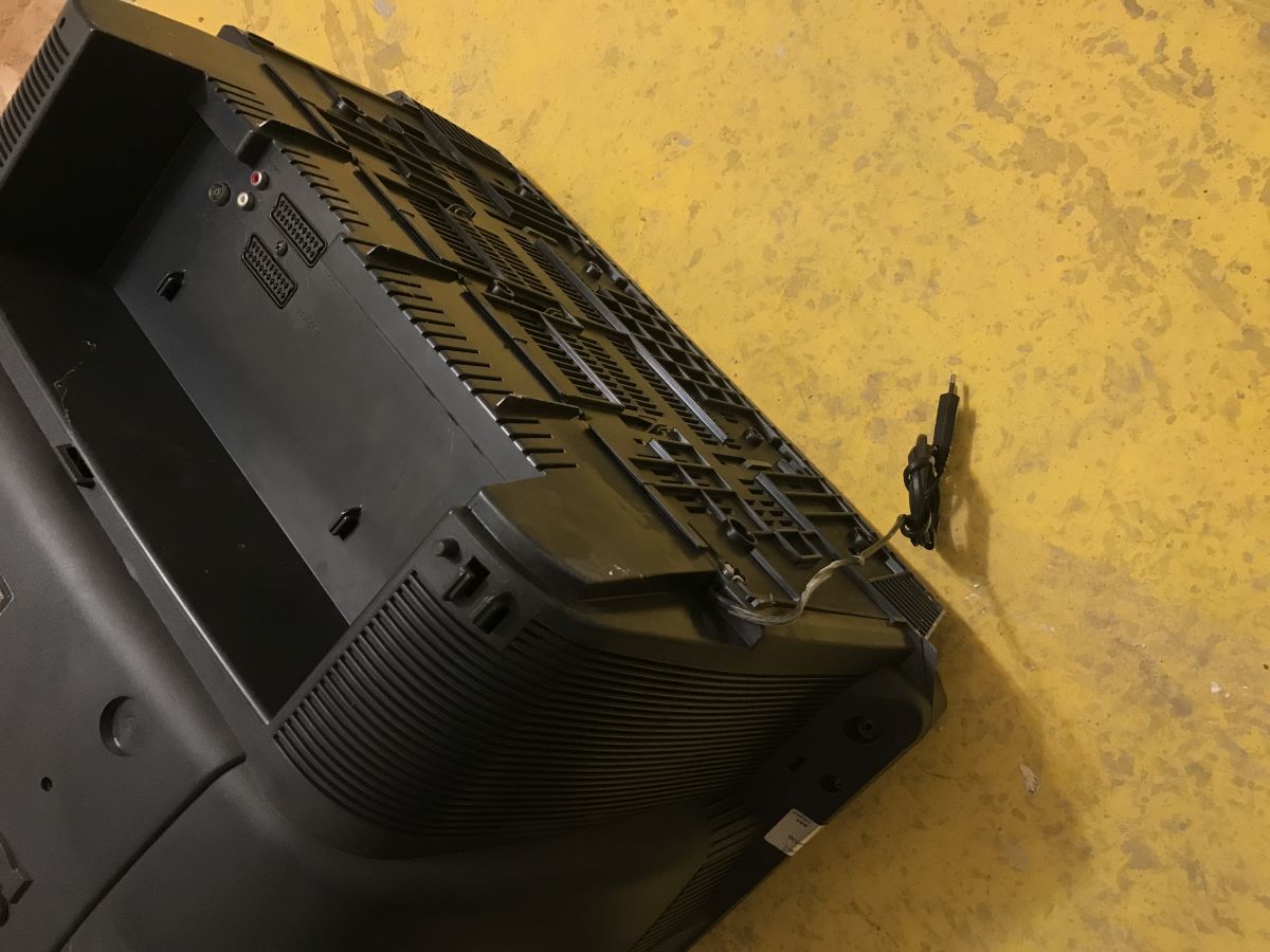
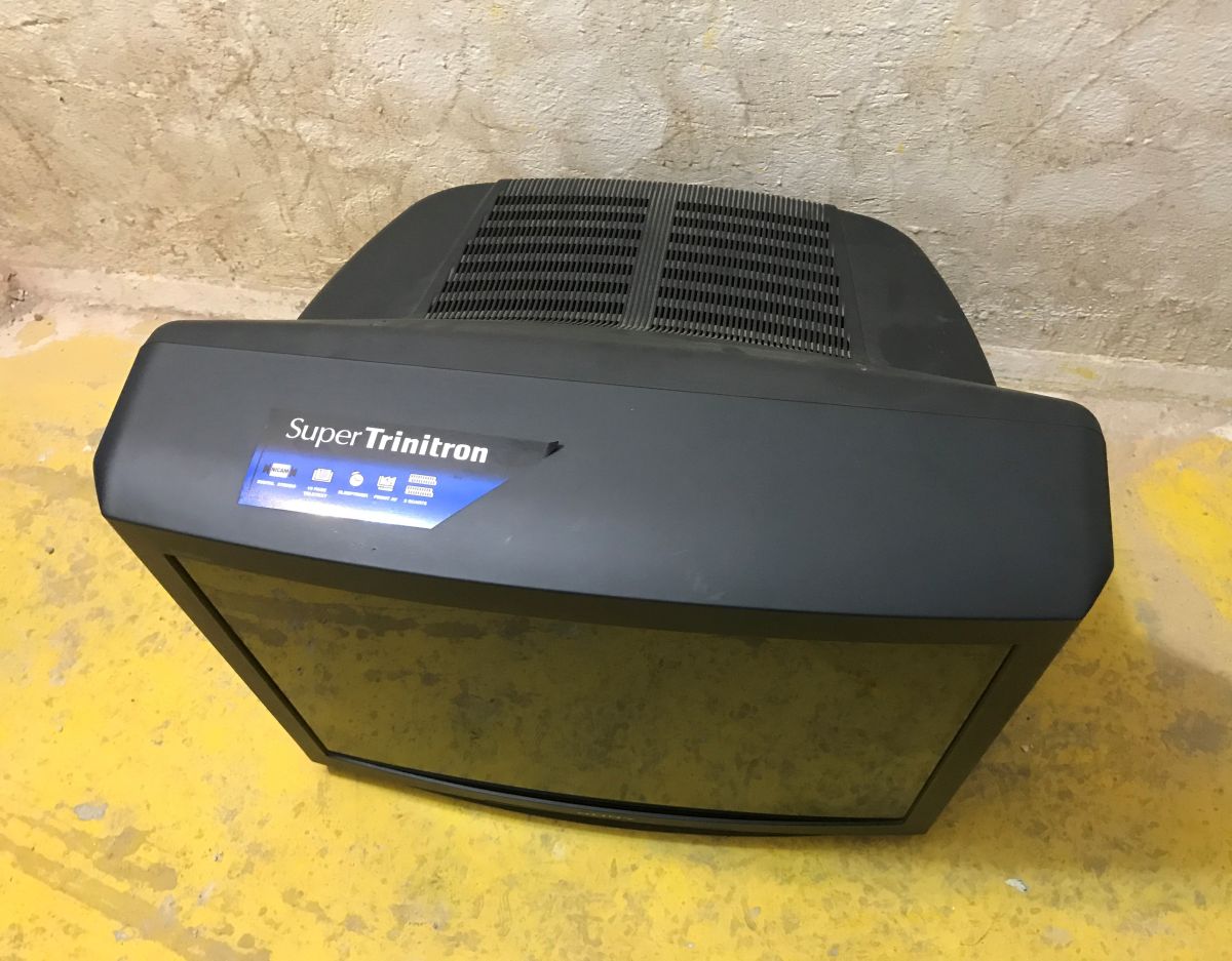
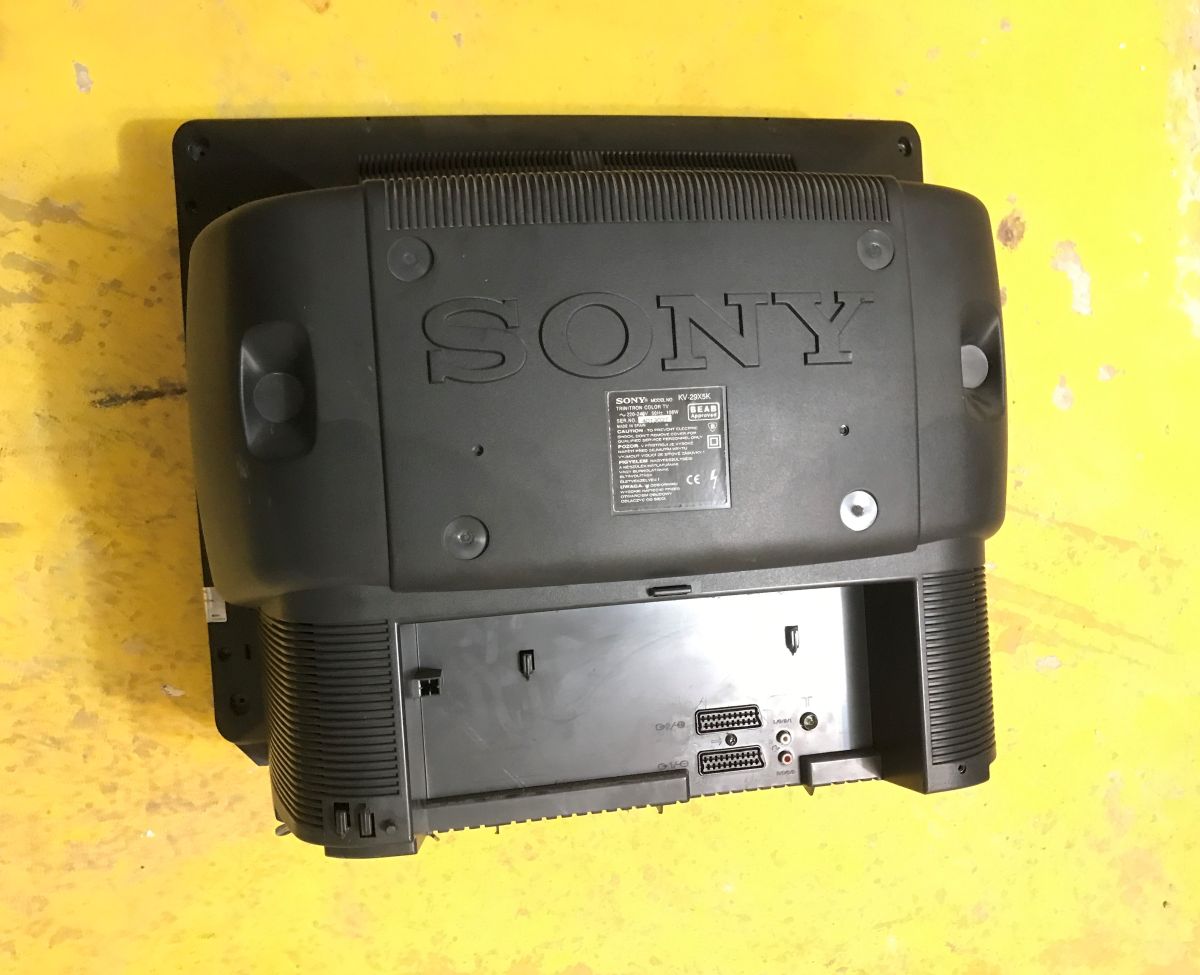
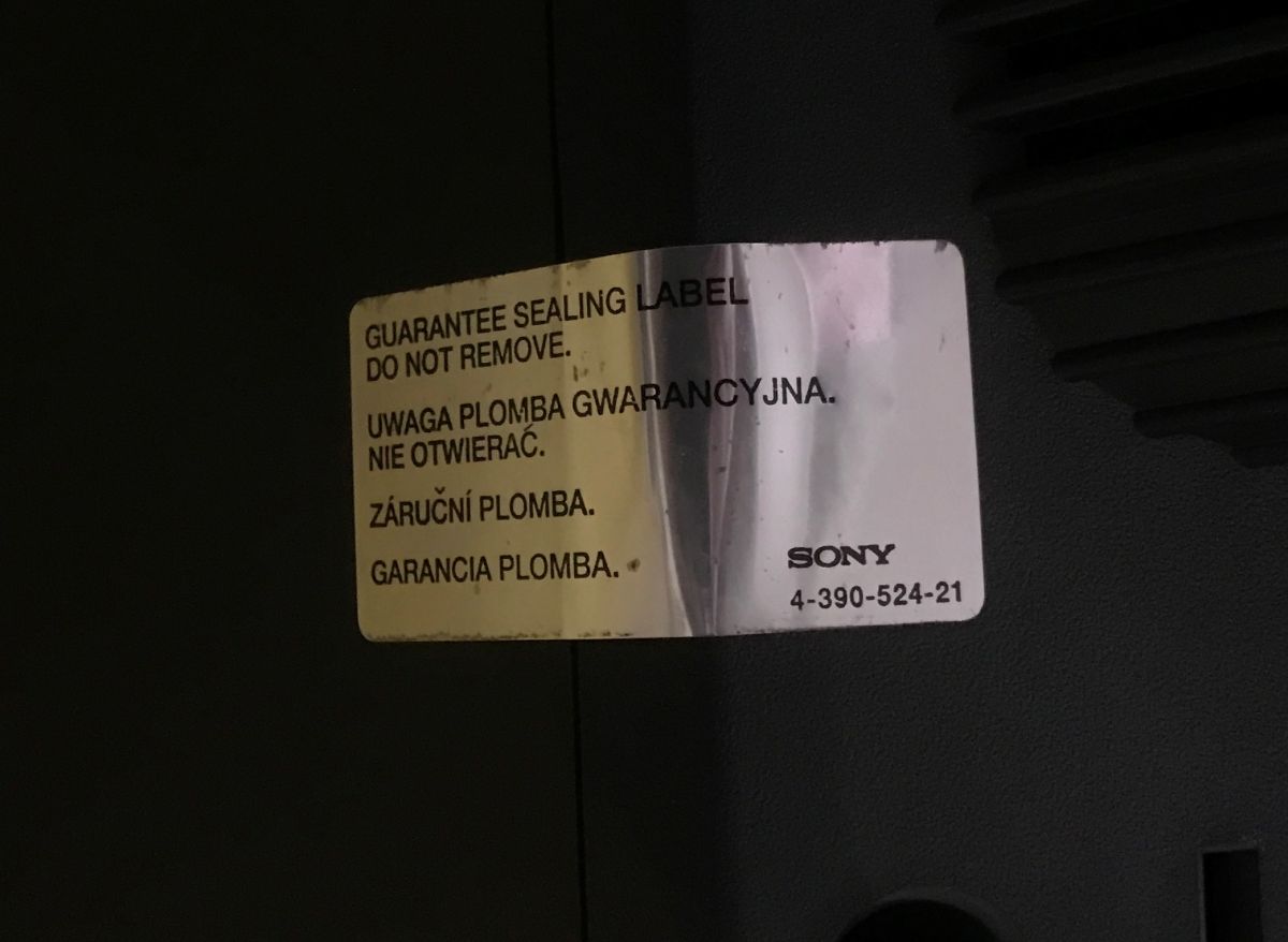
Warranty seal – has no one looked inside before?
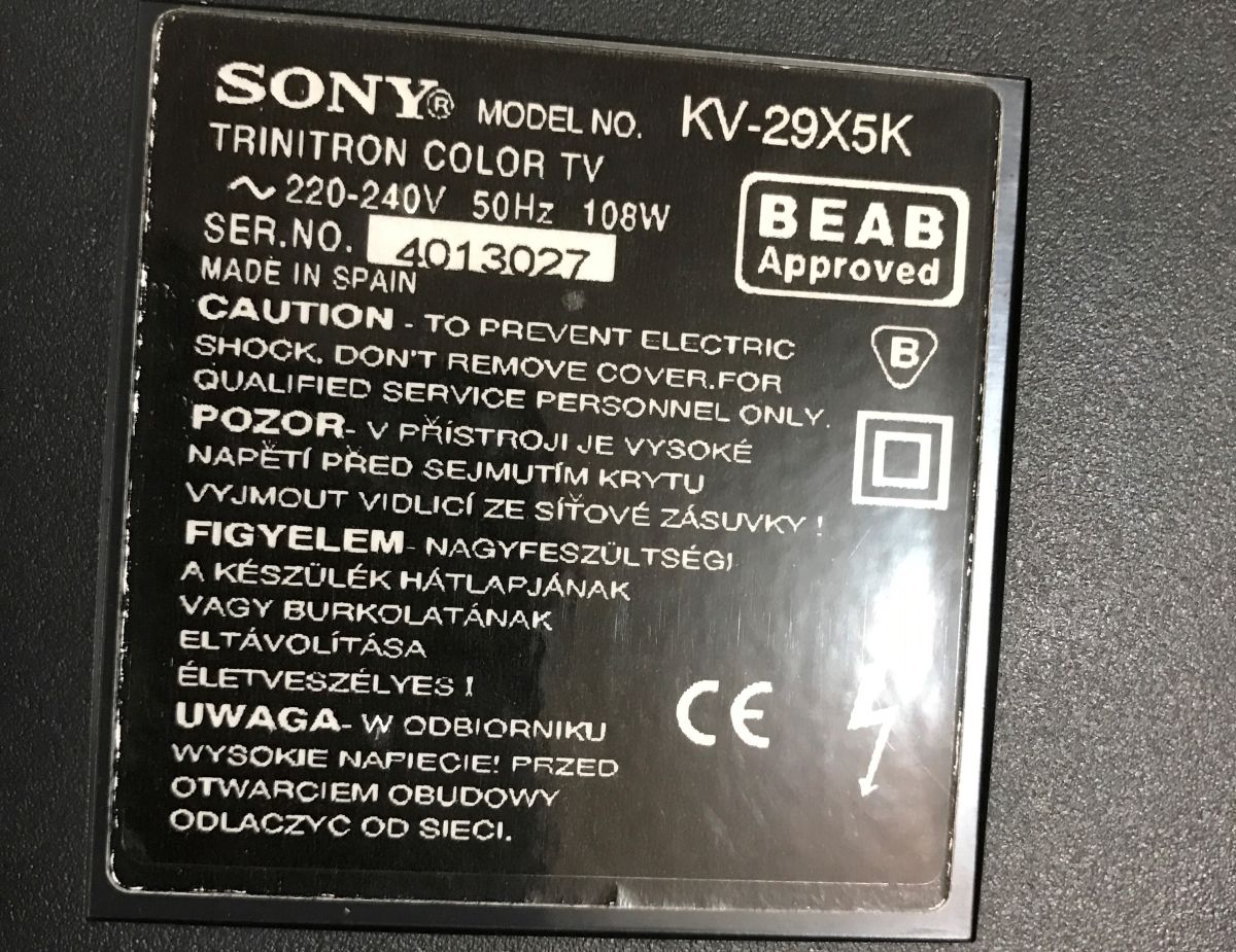
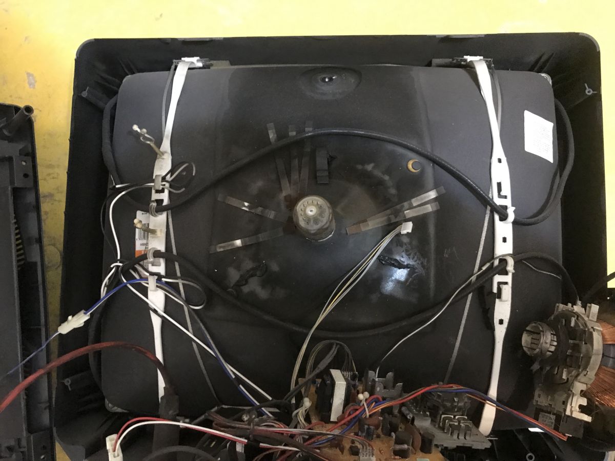
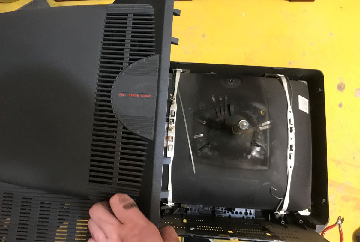
So ‘we’ll be the first ones here’. Just a quick glance at the type plate and we can remove the casing.
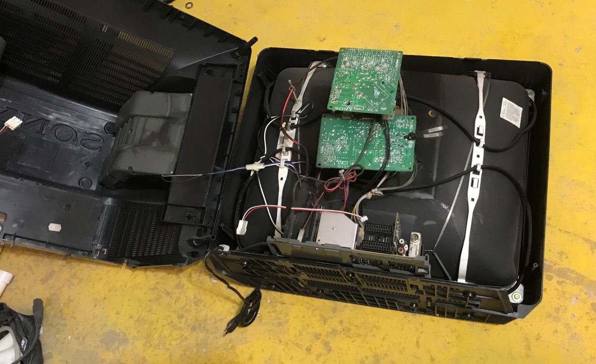
On the neck of the cathode-ray tube there is a circuit board (known as the PK), and beneath it is the deflection coil assembly. The role of these coils is to generate a variable magnetic field which deflects (scans) the electron beams vertically and horizontally across the entire width of the phosphor-coated screen. In turn, signals from the video amplifiers, fed from the PK plate directly to the cathodes, are responsible for ‘controlling’ the intensity of the beams for the primary colours (red, green and blue). The entire scanning process takes place so quickly that the human eye cannot perceive the movement of a single pixel, and we are left with the illusion of a smooth image.
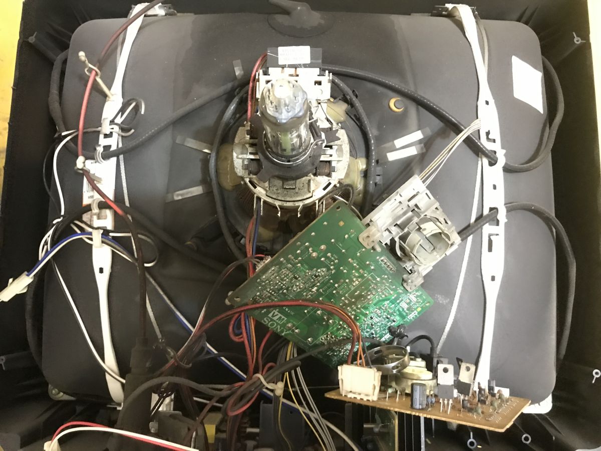
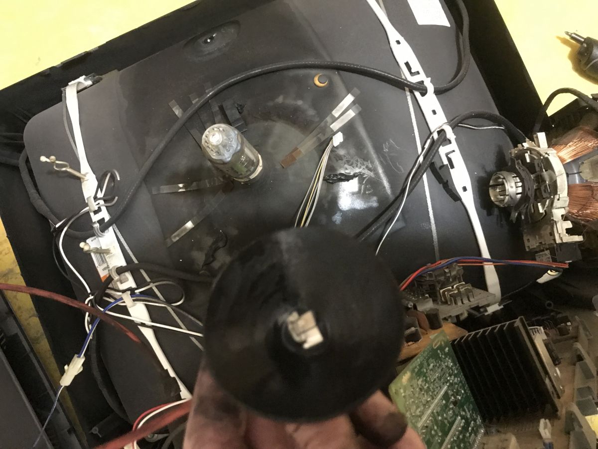
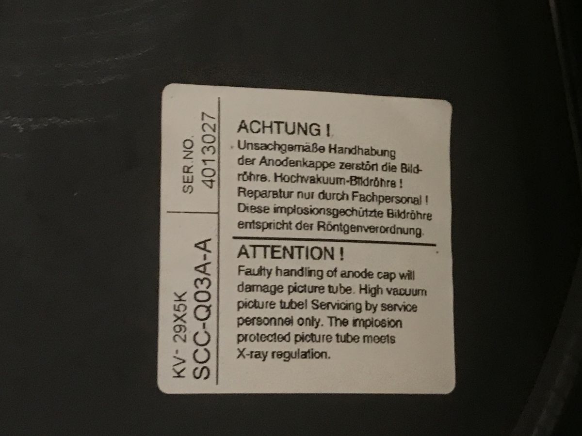
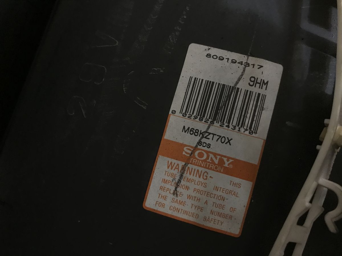
Picture tube designation:
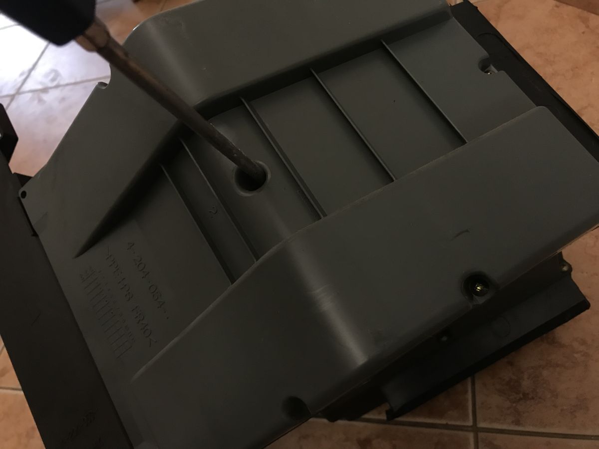
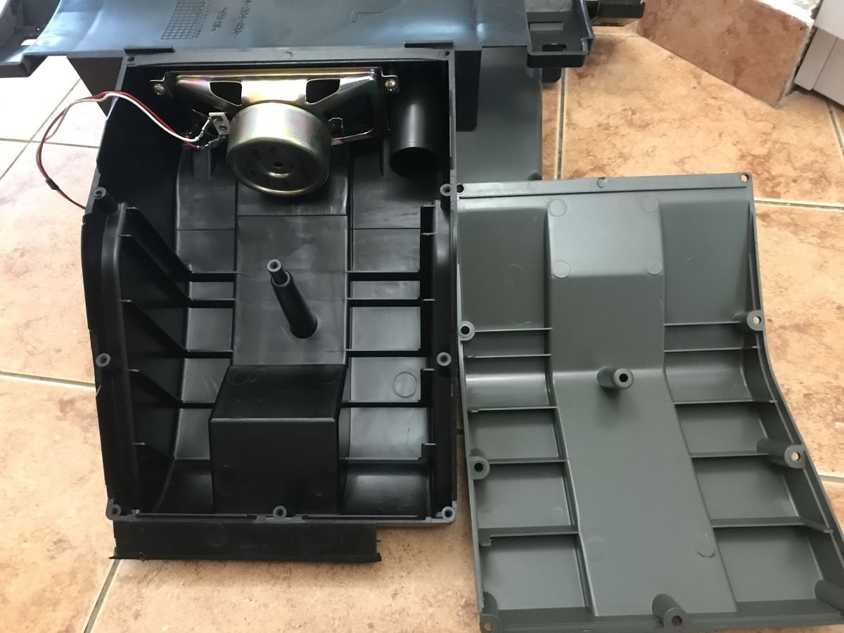
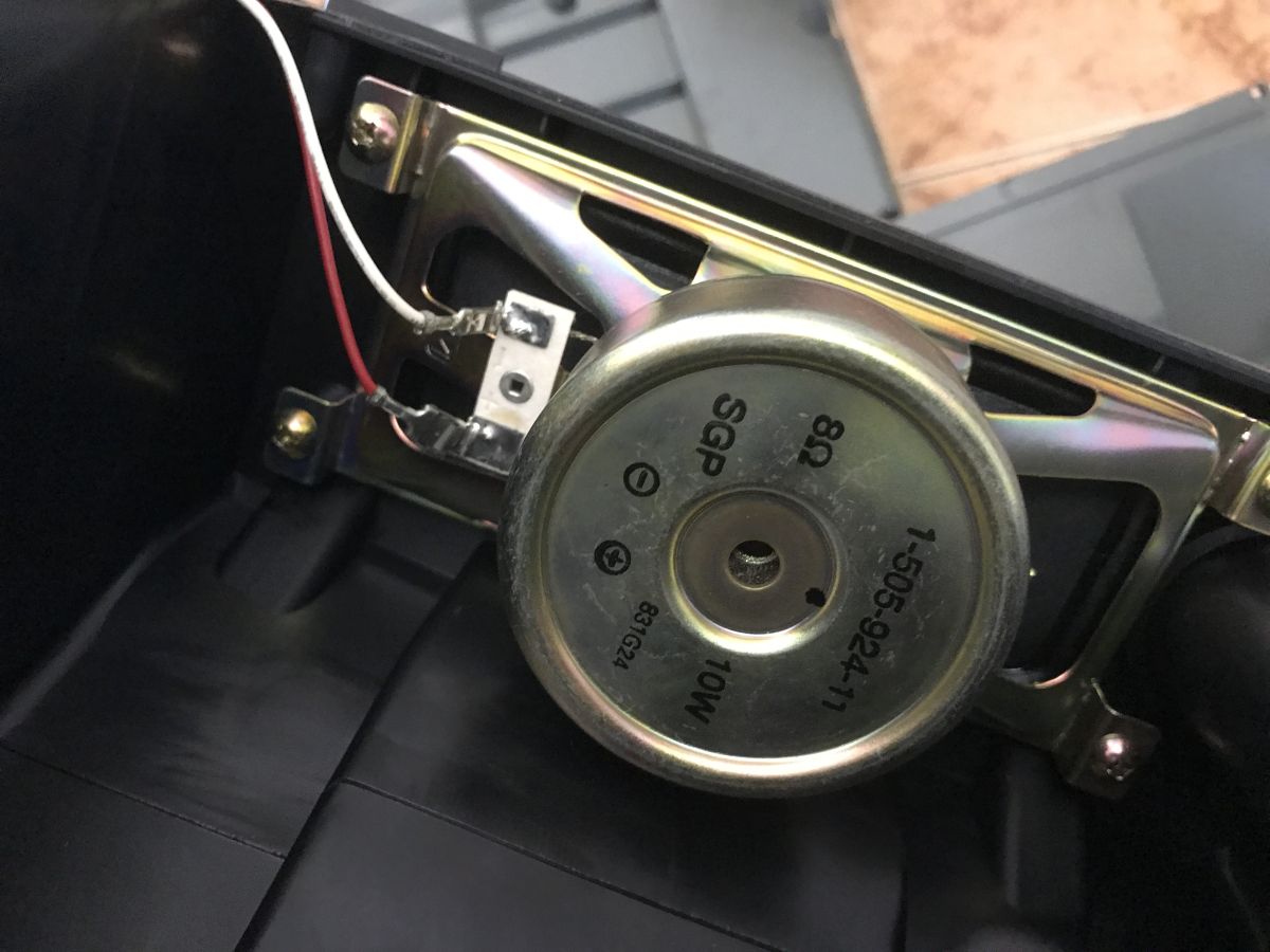
Earlier, I showed you an old Trinitron KV-21FT1K television with a single small speaker inside. Apparently, the mono sound was a natural consequence of the low price. Here, it’s quite the opposite – full stereo, and the speakers are even encased in a way that enhances their acoustic properties. Perhaps someone with expertise in audio could explain in more detail what effect this has, as I personally only have a basic understanding of music – I can tell when they’re playing and when they’re not...
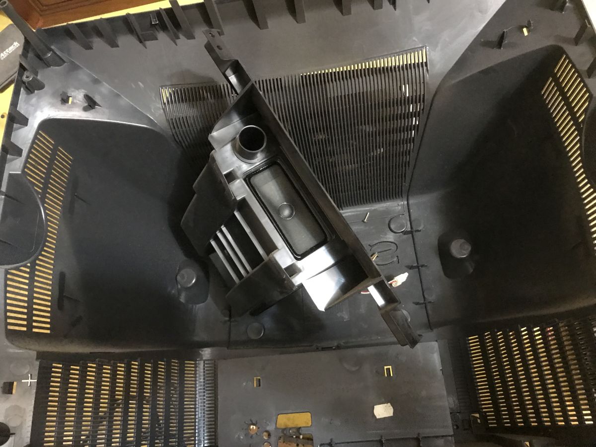
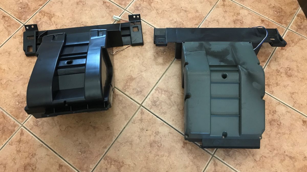
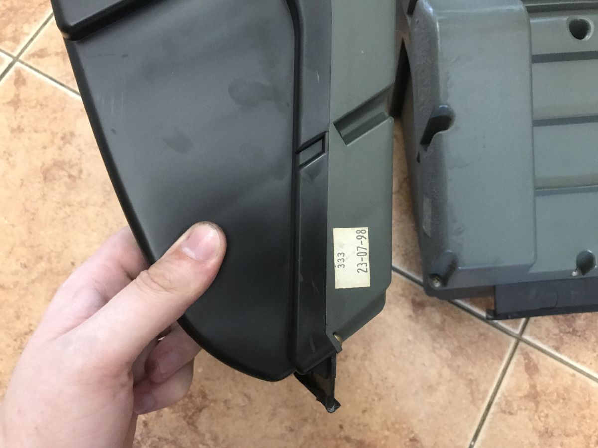
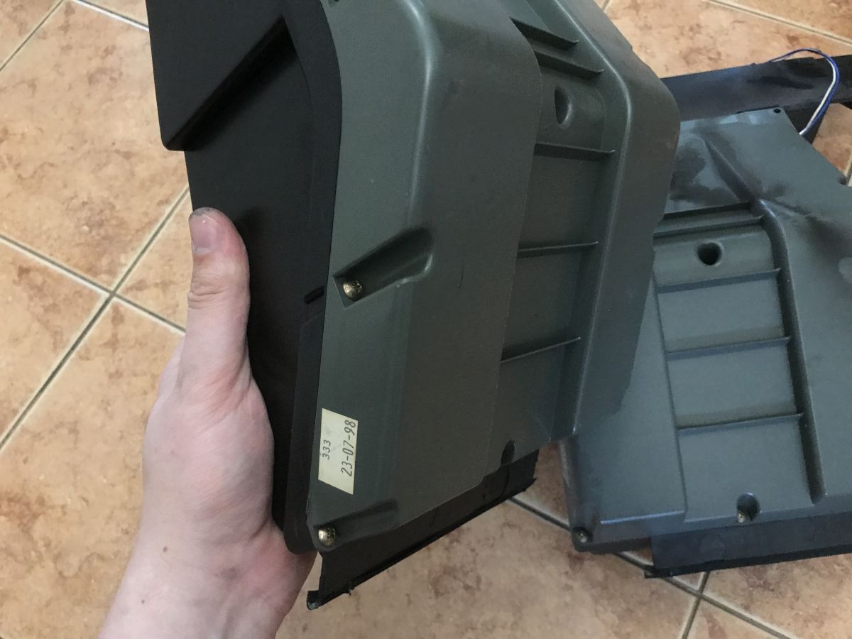
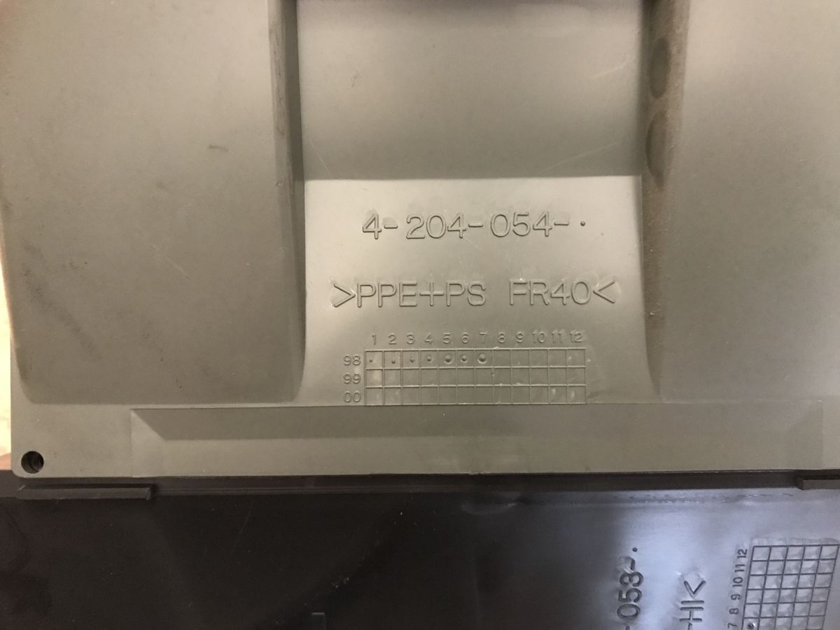
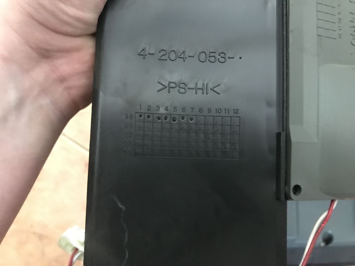
According to the embossed marking on the plastic, this part was manufactured in July 1998...
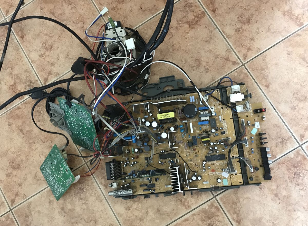
This is one of the newer sets, so many of the circuits have been simplified and there are dedicated integrated circuits inside for CRT operation, but there are still plenty of materials to be recovered. First and foremost, the coils – that is, copper – but the heat sinks (aluminium) are also quite large; you’d be hard-pressed to find anything like them in modern LCD televisions with LED backlighting:
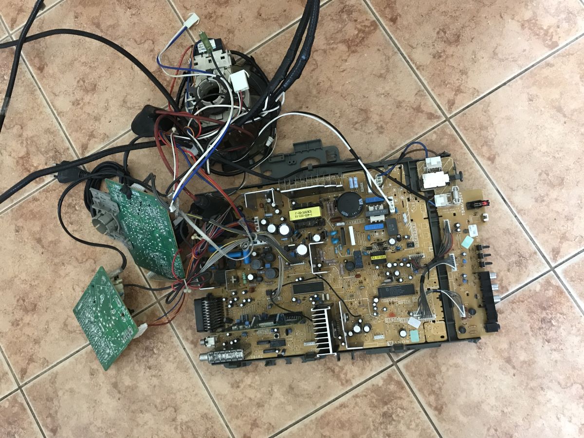
The main switch completely disconnects the television from the mains – both the live wire and the neutral wire are cut off. There is a separate standby switch; in standby mode, the television can be woken up using the remote control. In modern televisions, no one would bother with switches like these.
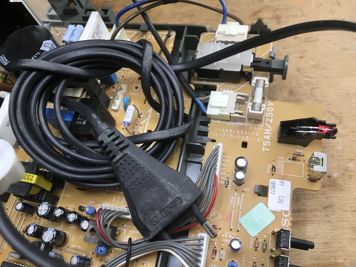
On the front panel, there are buttons (gone are the days when you’d have trouble accessing basic options if you lost the remote control), RCA sockets (audio – right and left channels, video), RGB, and even a headphone jack.
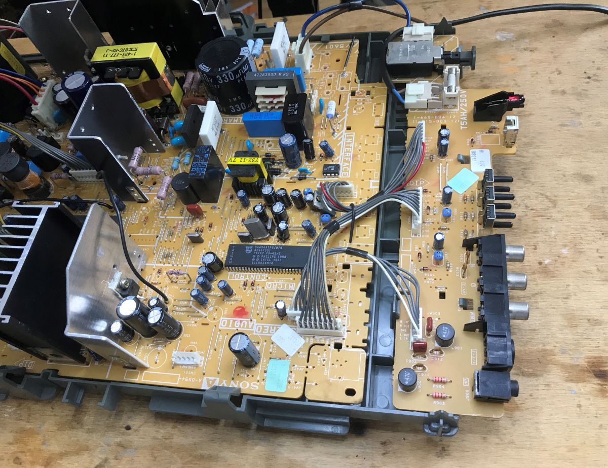
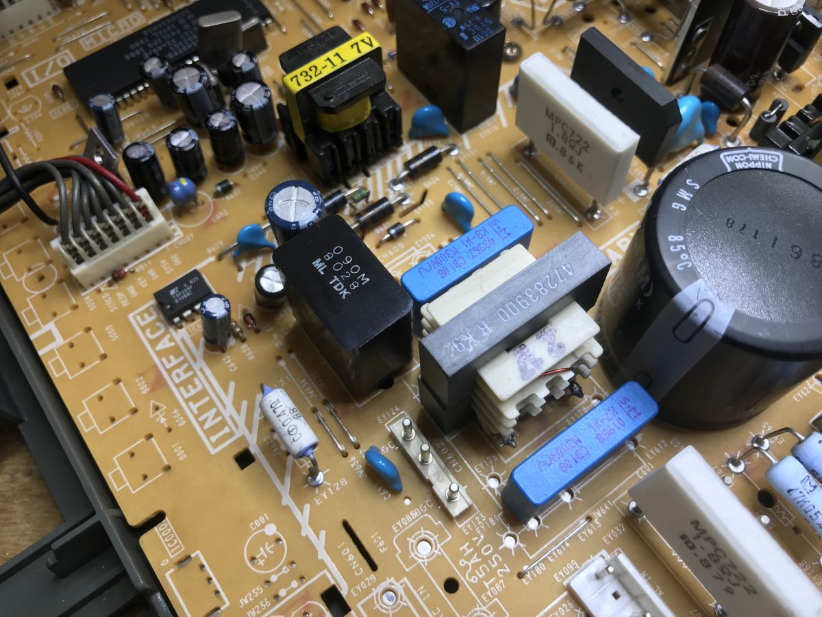
The mains power supply circuit essentially consists of two circuits. There is a tiny standby converter here, based on the TOP209P. This is an integrated PWM controller with a built-in MOSFET switch (TOPSwitch family), frequently used in standby power supplies due to the minimal number of external components required:
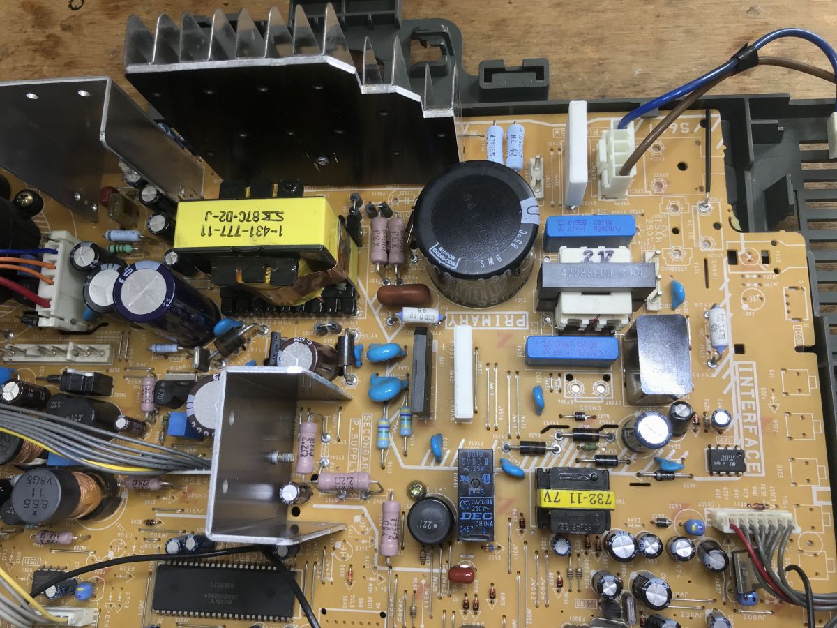
The main converter is switched on by the relay visible in the photograph. It is based on the F6654 STR (Sanken STR-F6654). This is a thick-film hybrid chip integrating a controller and a high-power MOSFET, designed specifically for use in switching power supplies for large-screen televisions:
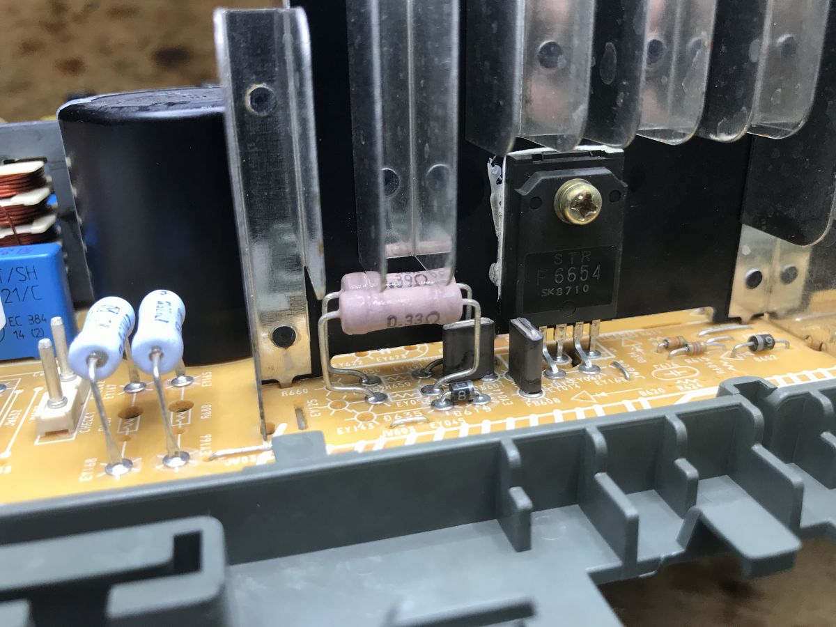
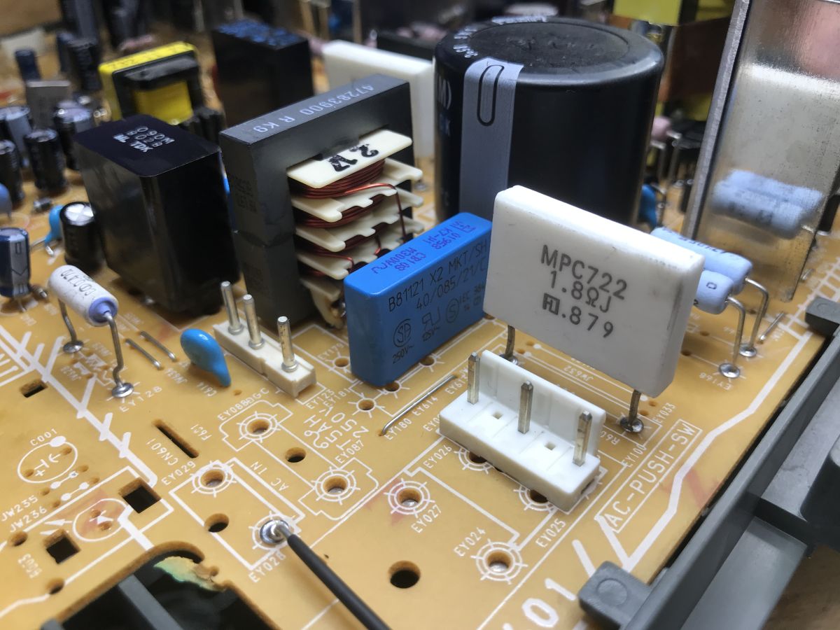
In a CRT television, there is also a separate circuit for horizontal deflection and for generating high voltage on the flyback transformer. The photograph shows its switching transistor, the D2539 (actually the 2SD2539), separately. This is a high-voltage NPN bipolar transistor with an integrated suppressor diode:
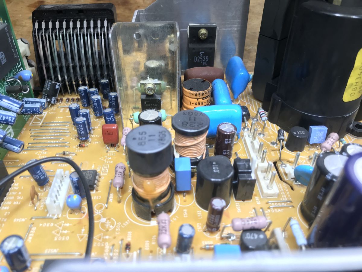
The SONY CXA2060S appears to be at the heart of the signal processing
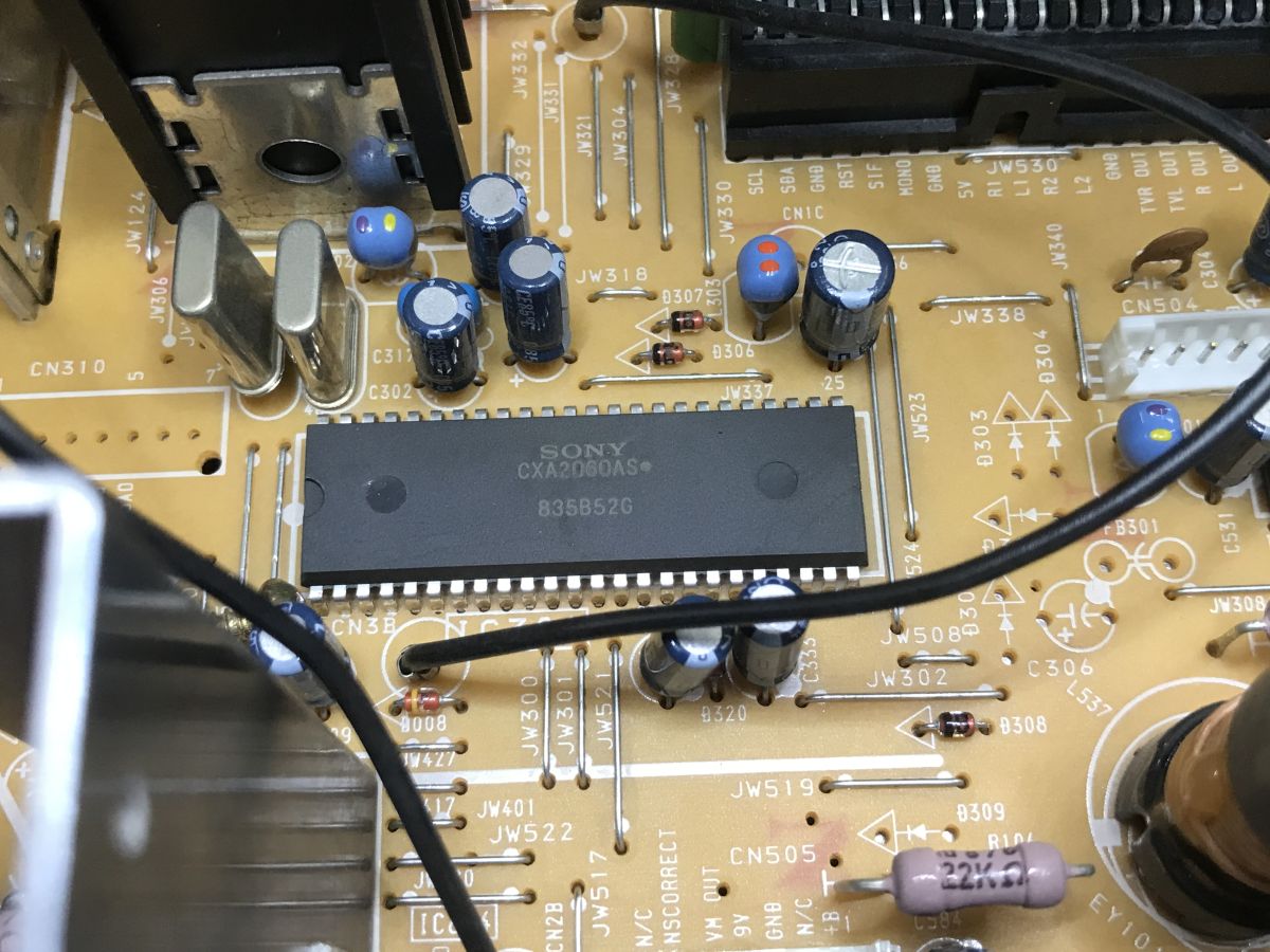
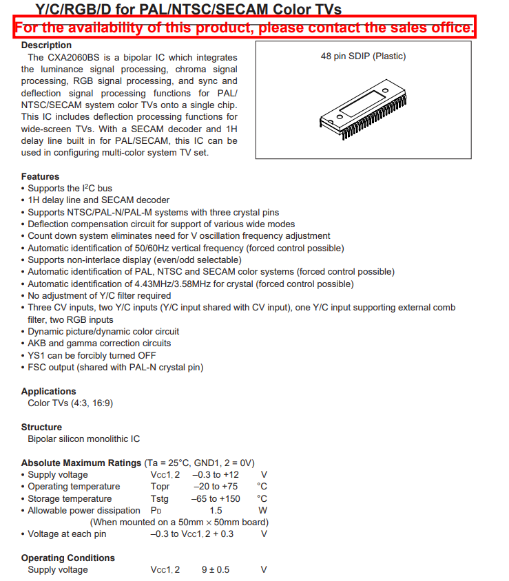
The CXA2060S is an advanced TV signal processor from Sony. It decodes colours in the PAL/NTSC/SECAM standards and generates signals for the deflection circuits, whilst its operation is digitally controlled by a microcontroller via the I2C bus.
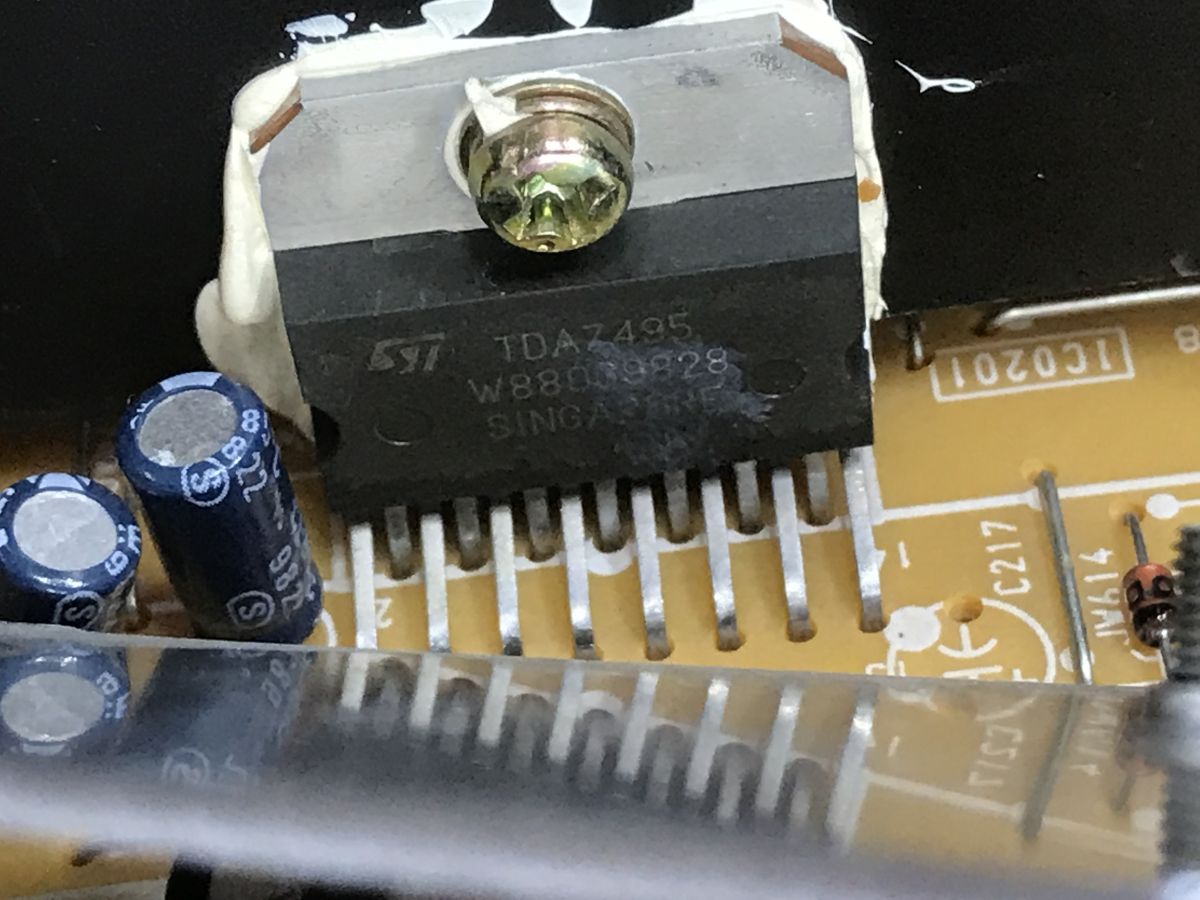
The TDA7495 is responsible for the audio. It is a Class AB audio amplifier IC from STMicroelectronics, capable of delivering 2×11W of power. It features an integrated, voltage-controlled volume control and a hardware mute function.
On the additional board, you can see the TDA9875A, which acts as an advanced digital signal processor (DSP). It decodes and processes the audio signal from the aerial, providing, amongst other things, support for the NICAM digital stereo audio standard mentioned at the beginning.
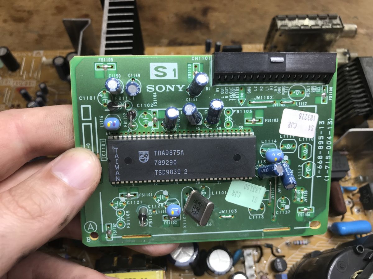
This can also be deduced from the signal labels – alongside the power supply, there are L OUT/R OUT (right and left channels) and an I2C bus (SDA/SCL) for control.
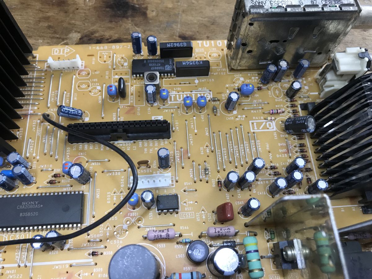
A TDA9817 can be seen at the aerial input. This is a phase-locked loop (PLL) circuit for demodulating the video intermediate frequency (VIF) and audio intermediate frequency (SIF) signals. In practice: it separates and processes the video and audio signals from what the tuner receives.
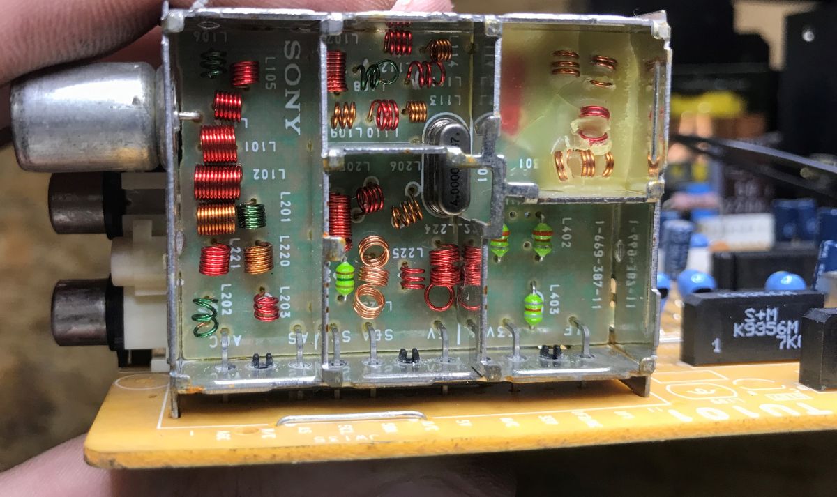
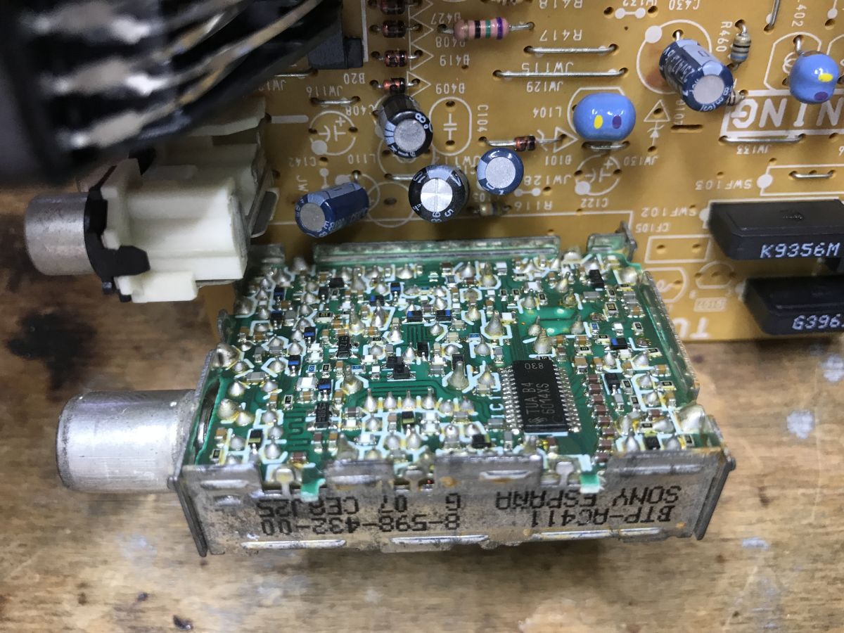
The tuner head itself likely contains a chip from the TUA6014 family. This is a phase-locked loop (PLL) from Siemens/Infineon designed for TV tuners. Thanks to I2C communication, it allows the main processor to precisely tune the TV to the selected band and channel.
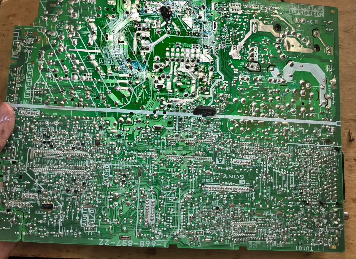
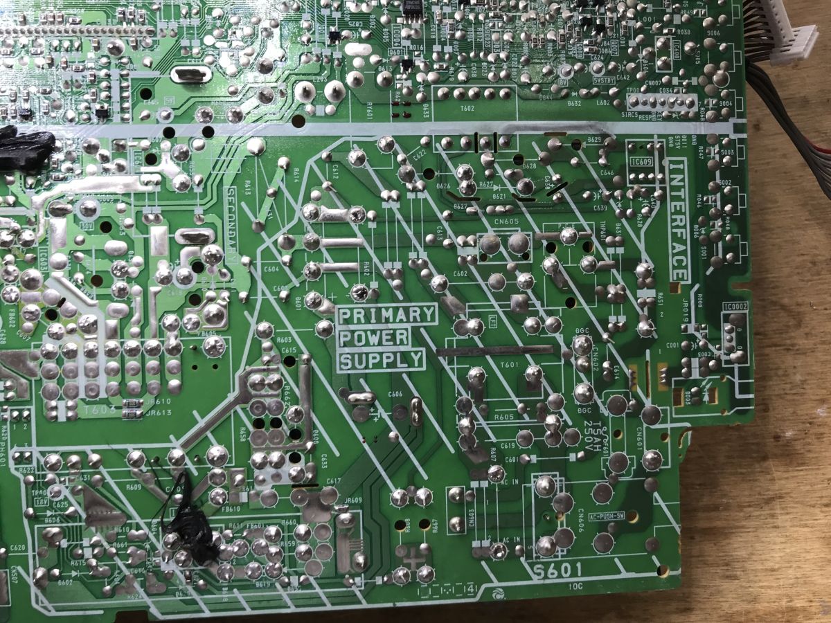
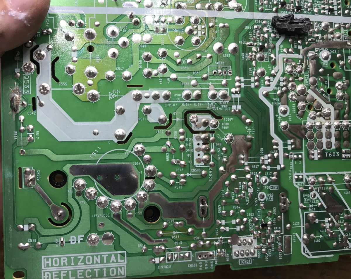
Overall, the PCB is single-sided and the vast majority of components are surface-mounted. On the underside, only a few SMD components can be seen, such as resistors, capacitors, transistors or individual integrated circuits.
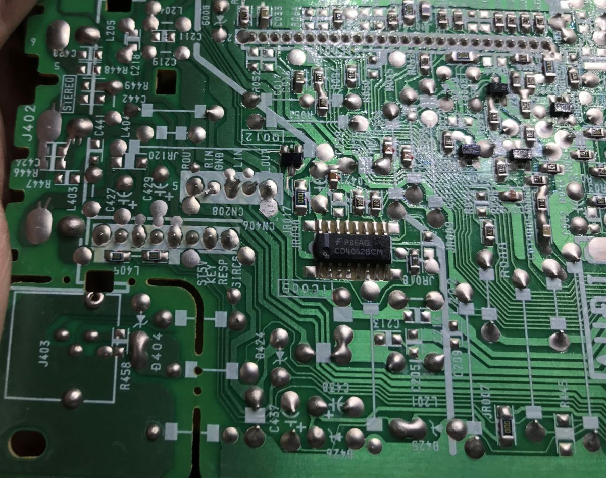
These include, amongst others, the 24W086 (a 1 KB EEPROM with an I2C interface, which stores user settings and values for service mode) and the CD4052 (a dual, 4-channel analogue multiplexer, presumably used to switch audio and video signals between inputs):
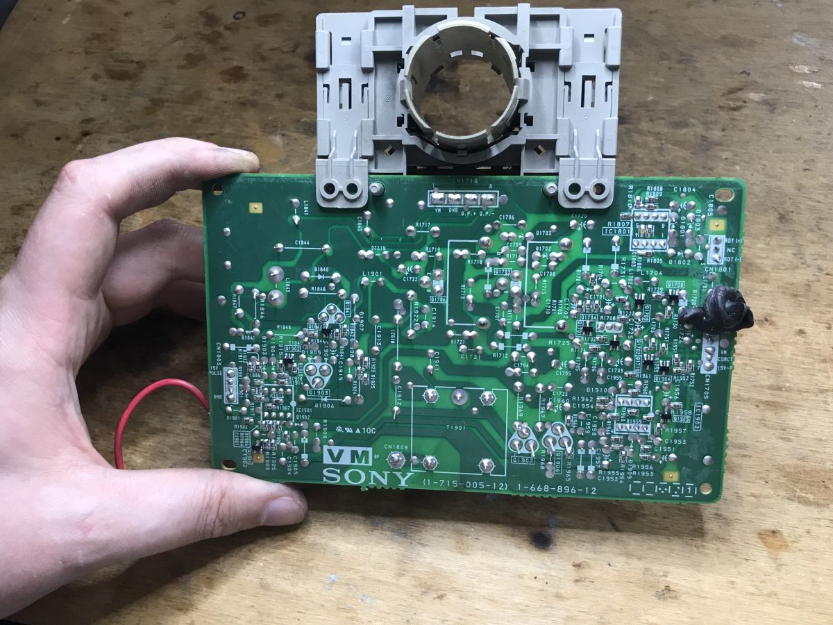
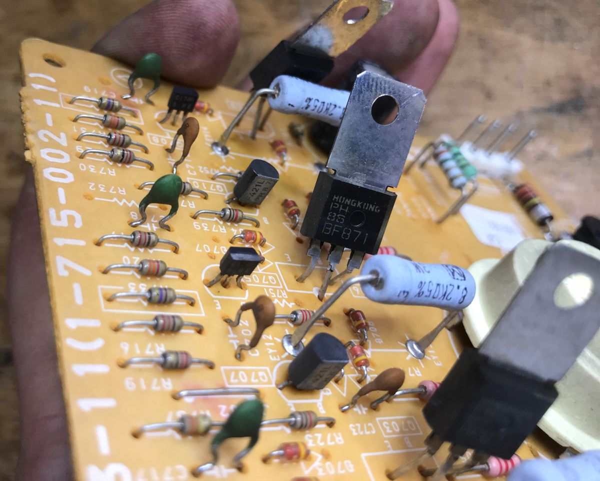
Here, in turn, is a view of the board from the neck of the cathode-ray tube – I can see three BF871s on it, as well as LM358 and LM393N chips.
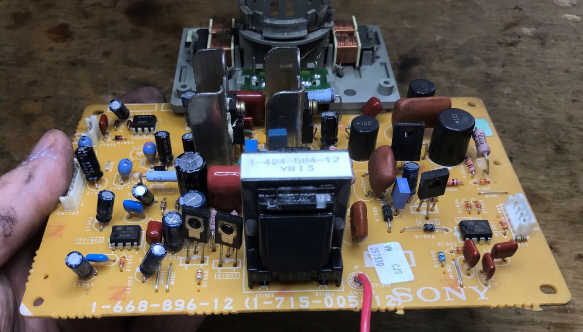
There are still the deflection coils left, as usual a bit glued together; recovering the wire would be rather difficult:
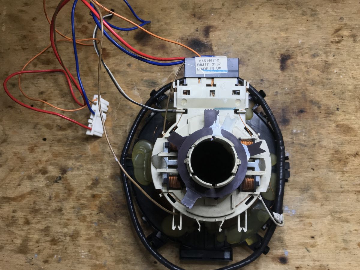
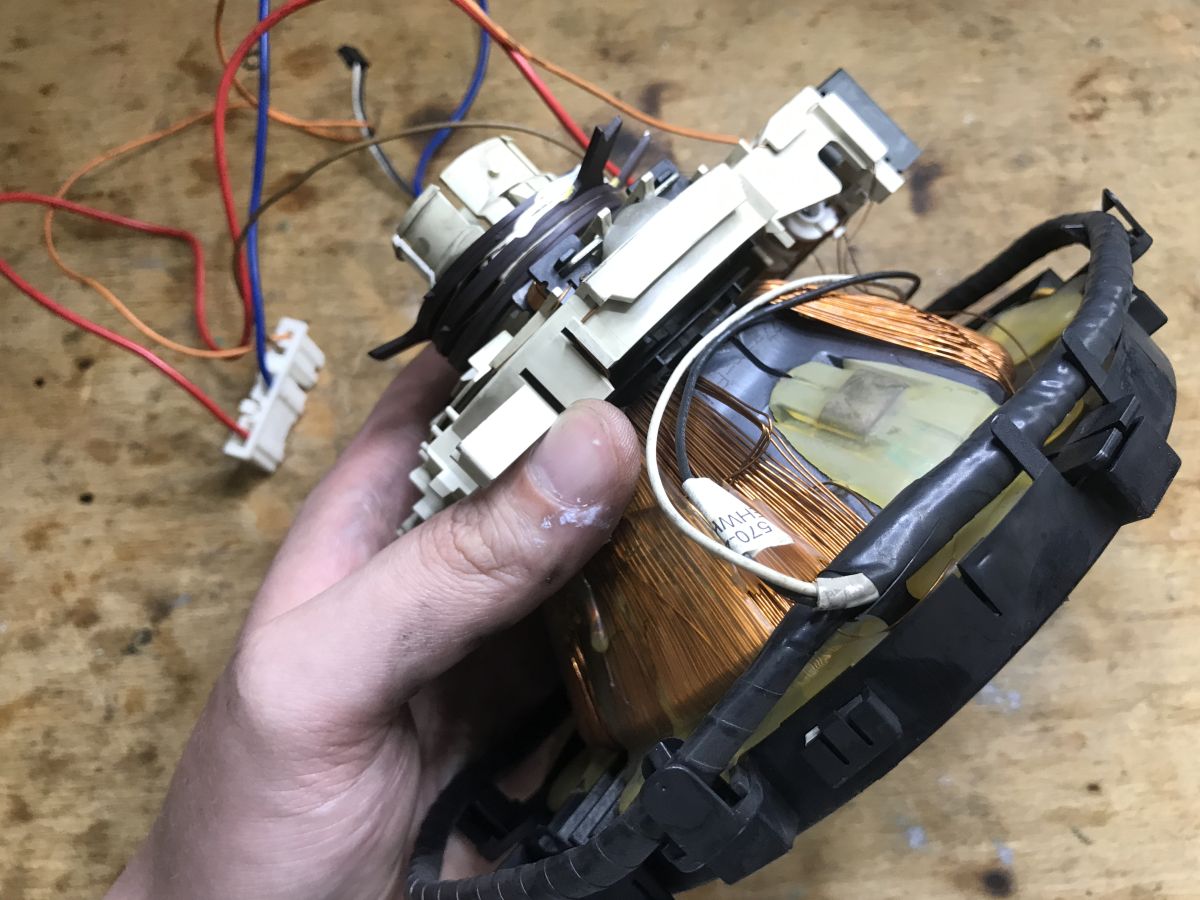
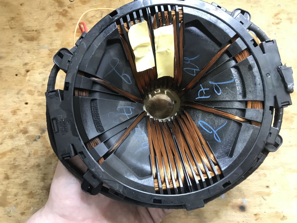
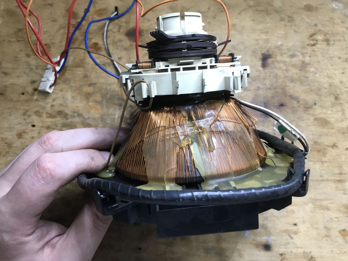
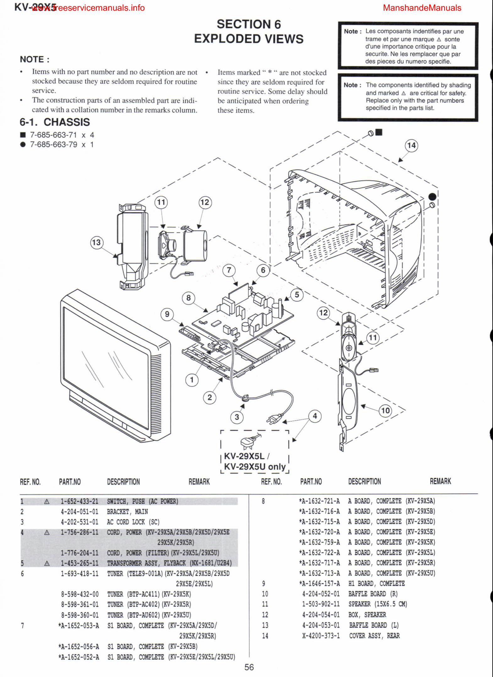
Finally, you can also have a look at the service manual. It is something completely different from today’s standards for equipment documentation. It contains everything, starting with an ‘exploded’ view with each component labelled:
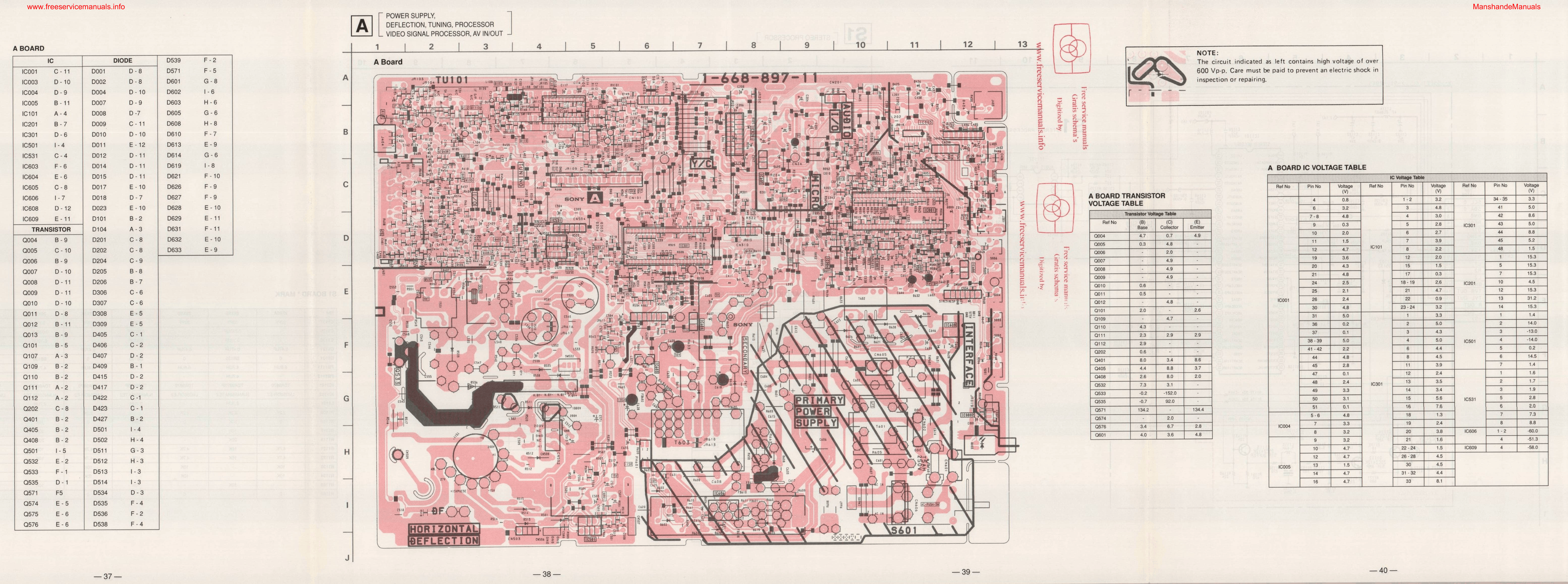
Through views of the circuit boards and separate schematics:
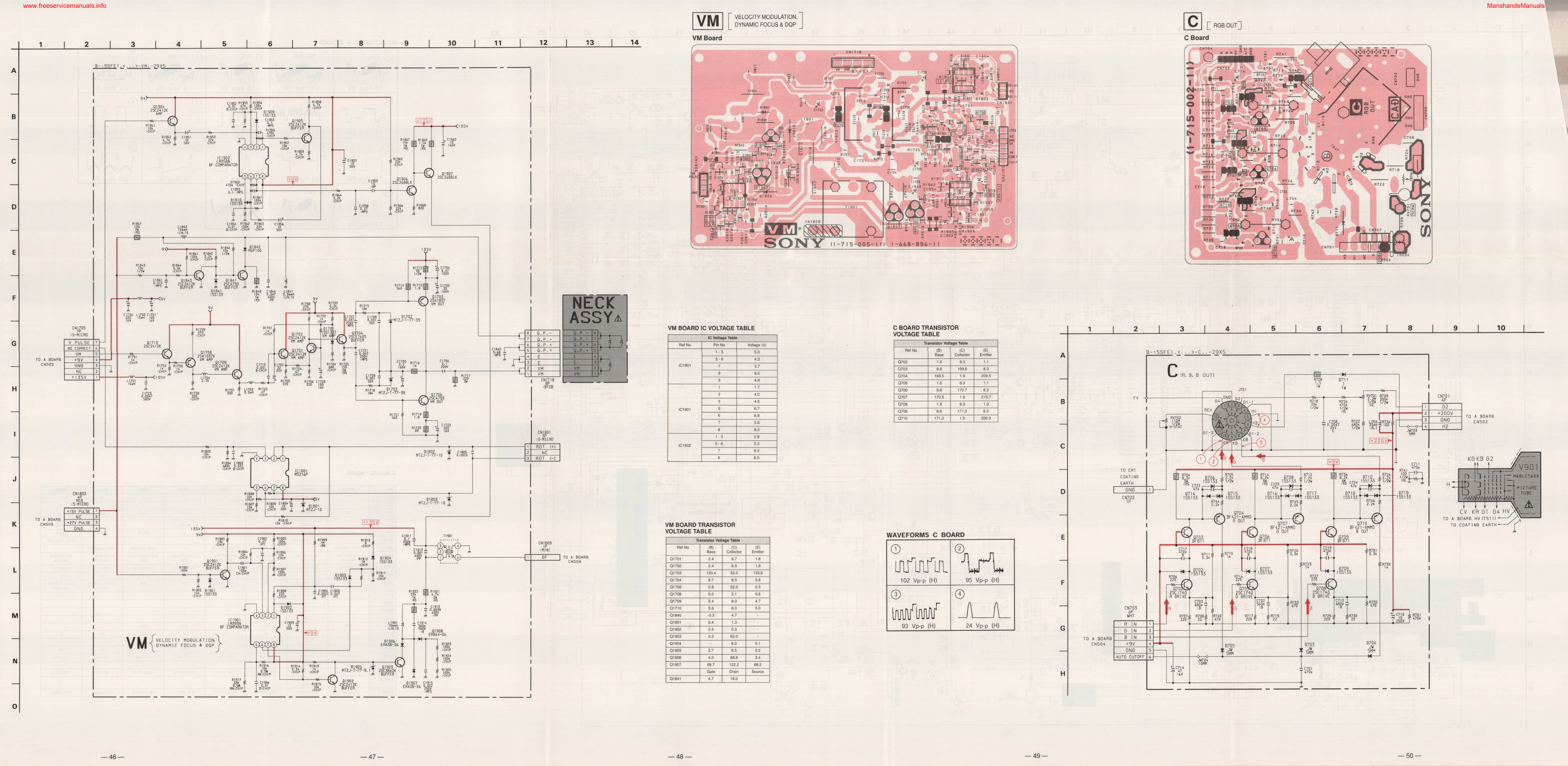
For example, the circuit board shown in the image matches almost perfectly with what I’ve provided in the photos, although there is a slight difference in the version – 1-715-005-12 versus 1-715-005-11. This really does make diagnosing and repairing faults much easier.
The documentation also describes the voltages at individual points and components – for example, for transistors, the values at the collector, emitter and base are highlighted. In some places, the expected waveforms are also shown, i.e. what you can expect to see on an oscilloscope.
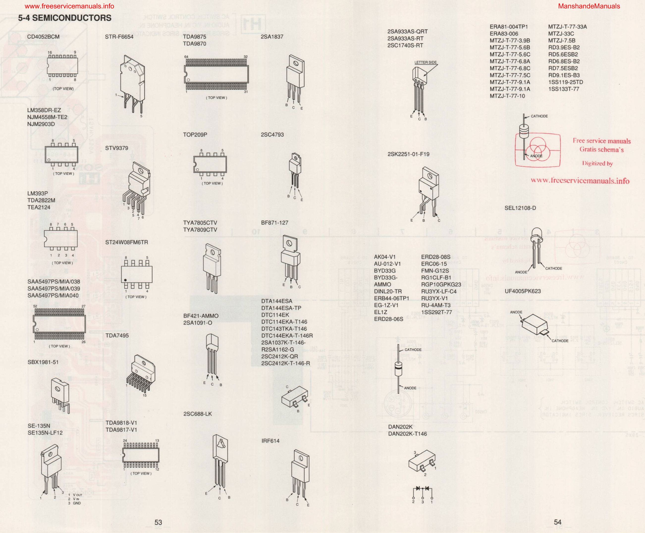
For convenience, a whole page has also been devoted to diagrams of the components themselves, complete with labelled pins.
To sum up, this was the interior of a 29-inch Sony Trinitron television, model KV-29X5K. Unfortunately, I barely remember those big CRT tellys at all; I think we only had a similar one during my early childhood, after which it was quickly replaced by a flat-screen TV. My computer actually started out with an LCD screen (I think it was a Flatron), so CRTs have always been a curiosity to me; that’s also why I decided to feature it here. It was a heavy piece of kit to carry in, but I suppose it was worth it for these few photos. What are your memories of televisions? CRTs – how user-friendly are they, and how prone to breakdowns? Have any of you had any models from the Sony Trinitron range?

p.kaczmarek2 wrote 14707 posts with
rating 12768 , helped 658 times.
Been with us since 2014 year.
Comments
A popular model – I often came across them in people’s homes, and I actually had a similar one myself for a while. It’s true, the sound quality was very good, but unfortunately I often saw this model... [Read more]
A Trinitron like that must have been heavy. I had a Grundig 100 Hz, a flat-screen model, but the Soby weighed more because of the design of the cathode-ray tube. Mine weighed about 15 kg (or was it about... [Read more]
This one has a slightly curved screen; the flat ones weighed even more. The quality of the CRTs went downhill after production was moved to Europe – to my recollection, to the UK and Spain. [Read more]
It used to be everyone’s dream. [Read more]
I remember them perfectly well, and I actually stuck with that technology for quite a long time. Not only that! For a very long time, I believed that CRTs produced a better picture than LCDs, even though... [Read more]
Screens are getting bigger and bigger, whilst the content on TV is getting sillier and sillier. [Read more]
Contrary to what one might think, there is actually some truth in this. From what I’ve heard, NES games and the like were designed with CRT monitors in mind, and they look better on a CRT, although I haven’t... [Read more]
Yes, because that was real television, delivering a dynamic picture. I’ve already mentioned here on the forum that, as a Formula 1 fan, I saw the best picture quality on a CRT TV and analogue satellite... [Read more]