






The DTSU666 bidirectional, three-phase electricity meter and data retrieval via Modbus on the ESP32
TL;DR
- An ESP32 reads a DTSU666 bidirectional three-phase electricity meter over RS485/Modbus RTU for real-time voltage, current, power and energy monitoring.
- The setup uses a LilyGO T-CAN485 transceiver, connects A-to-A and B-to-B, and treats the meter as a Modbus slave polled by the ESP32 master.
- The meter occupies 4 DIN modules, weighs just under 400 grams, and costs around 250 zł.
- PlatformIO with OTA support and the ModbusMaster library made reading registers straightforward, including 32-bit float values such as phase L1 voltage from register 0x2006.
- The meter and firmware must share the same RS485 settings, baud rate and slave ID, and longer cables may need a 120 Ω terminating resistor.
AI summary based on the discussion. May contain errors.
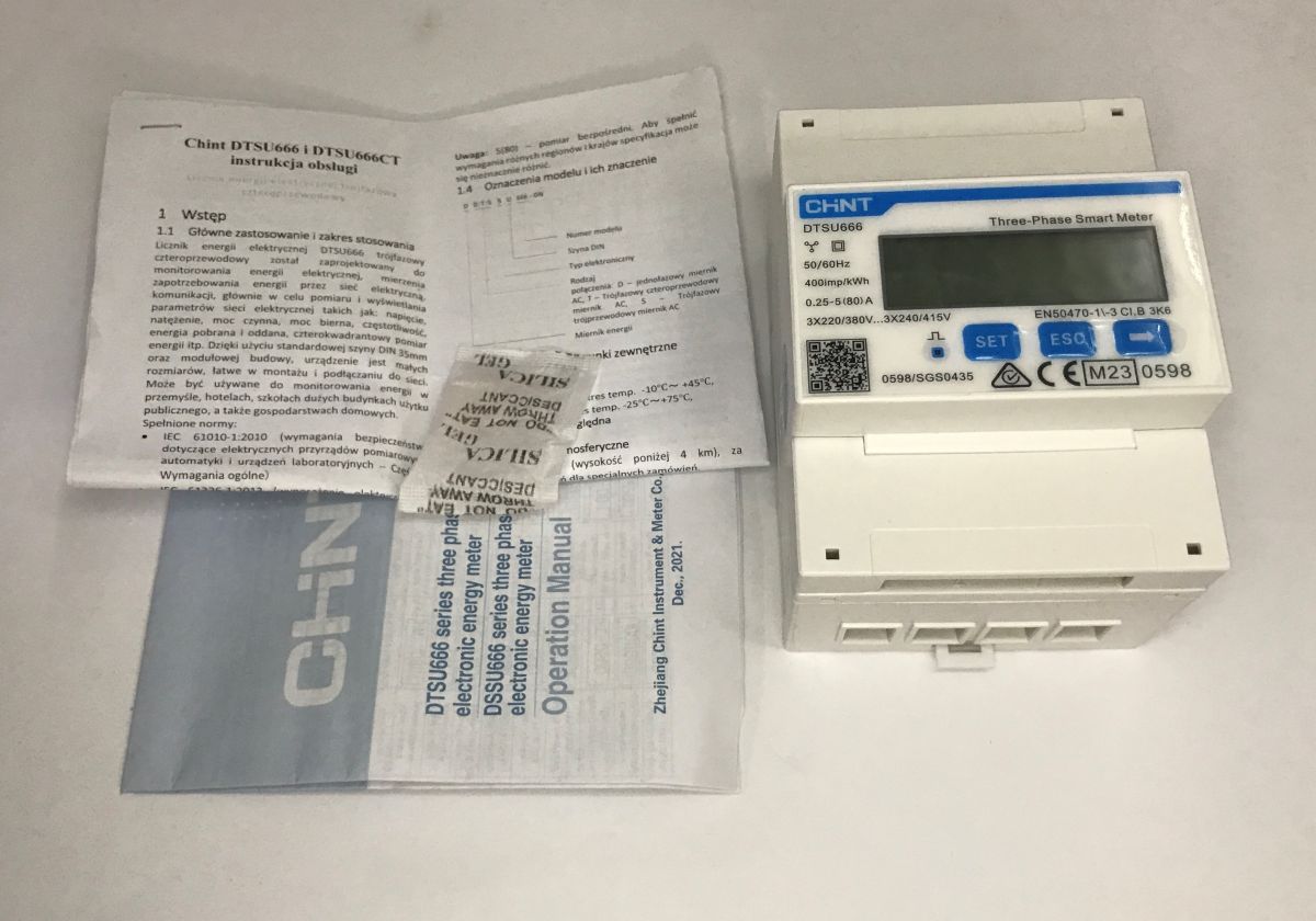
The DTSU666 is an electronic, three-phase energy meter designed for mounting on a DIN rail within a switchboard. Thanks to its built-in RS485 interface and support for the Modbus RTU protocol, this meter is well suited to reading real-time data on voltages, currents and power, allowing for easy integration into your own projects. This is exactly what I’ll be demonstrating here, using a ready-made ESP32 board.
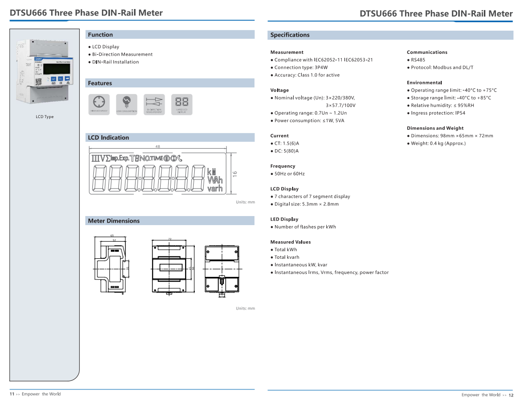
I bought the DTSU666 from a Polish online shop for around 250 zł. The device occupies 4 standard DIN modules (72 mm wide) in a switchboard and weighs just under 400 grams. It is also fitted with a backlit LCD display, which allows you to conveniently view the current voltage, currents and energy metered on individual phases without the need for any additional apps, as well as to configure Modbus. The pack also included a Polish-language manual.
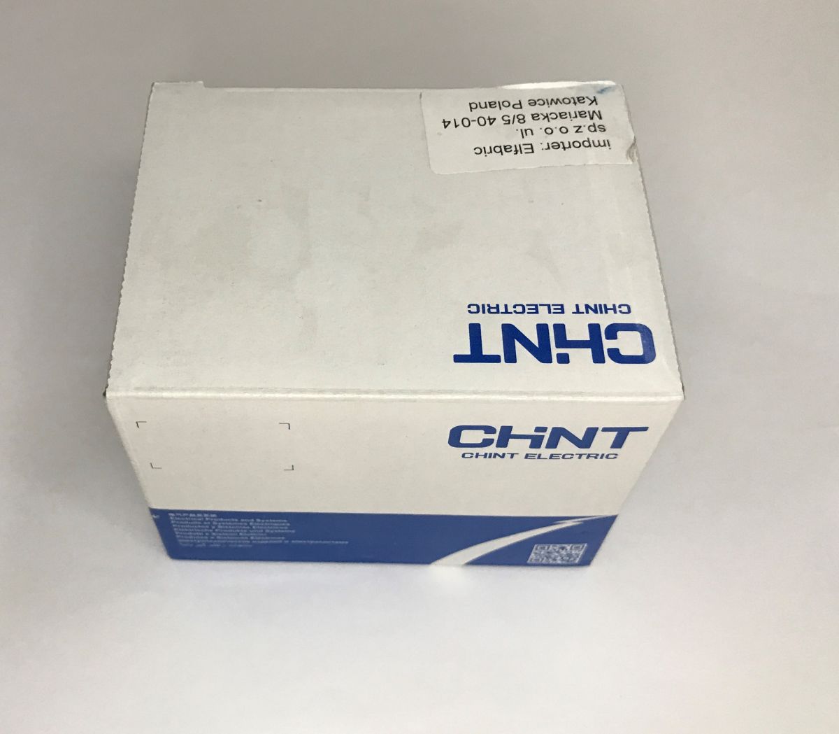
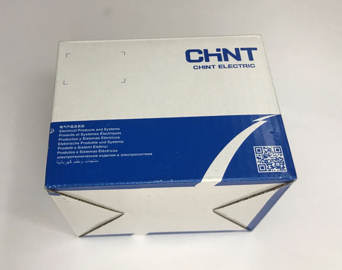
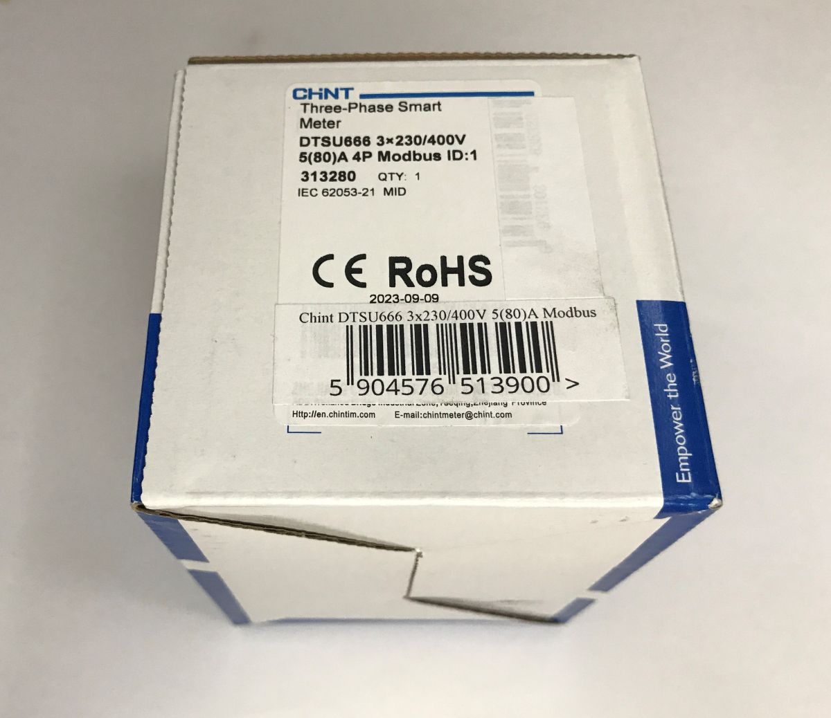
Connecting the DTSU666 is fairly straightforward – even the sticker on the side lists the pins, including the RS485 port and the pulse output.
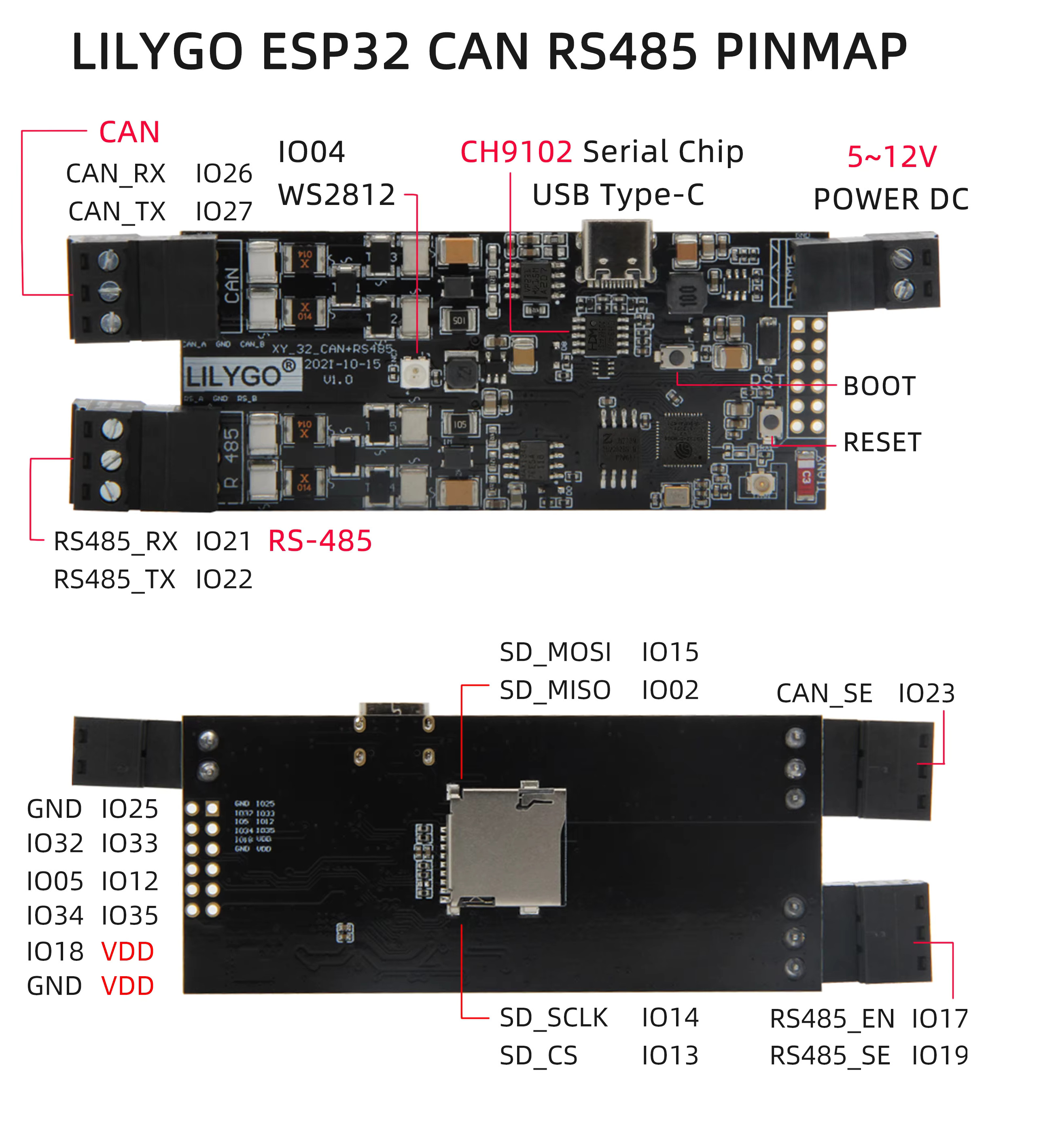
The RS485 port is used here for communication via the Modbus RTU protocol, which is widely used in industry. RS485 itself is merely a physical layer based on a differential signal, providing high resistance to interference and ranges of hundreds of metres. From the microcontroller’s perspective, it is handled in exactly the same way as a standard UART serial port (RX and TX pins); however, the signal is not directly compatible. To bring it all together, you need a suitable hardware converter (e.g. based on the popular MAX485 chip) or a ready-made board that already has such a transceiver built in. Here, I decided to use the previously featured LilyGO T-CAN485 – an ESP32 for learning industrial communication, RS485 and CAN buses .
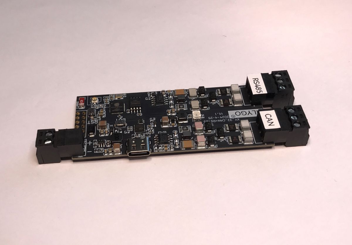
We simply connect pin A to A and pin B to B. We do not ‘cross-connect’ (from RX to TX) as with UART, because RS485 is a bus to which we can connect multiple devices in parallel. Communication is managed by a single master device – in this case, our ESP32, which polls the rest of the network. The other devices are known as slaves (in this case, the DTSU666 meter), which simply listen and respond to commands from the master. For longer cables, it is also worth remembering to connect a terminating resistor (usually 120 Ω) at both ends of the bus, which will prevent signal reflections.
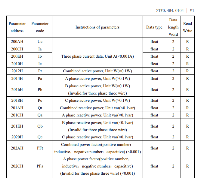
Modbus is a widely adopted standard for data transmission between machines, which enables the standardised exchange of information through simple frames. The most important concept of this protocol is that all variables read and written are stored in so-called registers. Registers have different types and addresses, which can be found in the documentation. From the table below, we can see that, for example, phase voltages start at register 0x200A, are 32-bit (2 registers) and are of type float, i.e. floating-point.
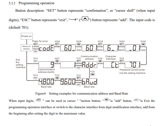
RS485 can operate with various port and baud rate settings, whilst Modbus supports various slave IDs. These settings must match between the meter and the firmware. On the meter, they can be changed via the UI:
Now you’ll need the firmware. The simplest way is probably to write it in PlatformIO, which is an extension for the Visual Studio Code environment. It makes it easier to manage external libraries and automates the download of the appropriate compilers for our board. The project configuration is saved in its entirety in a single platformio.ini file, which greatly simplifies transferring code between different computers.
I started with the basics, namely setting up over-the-air (OTA) programming and a simple website:
How to programme the Arduino-style Wemos D1 (ESP8266) board? ArduinoOTA in PlatformIO
Next, I added the ModbusMaster library to the project:
https://github.com/4-20ma/ModbusMaster
My platformio.ini:
Code: Ini
With the library now added to the project, querying the meter is essentially just a matter of calling a single function. Below is a short code snippet showing how to read the 32-bit voltage value for phase L1 (address 0x2006). Please note that after a successful read, we need to combine two 16-bit registers into a single
floatand divide the result by 10 – exactly as required by the manufacturer’s documentation.
Code: C / C++
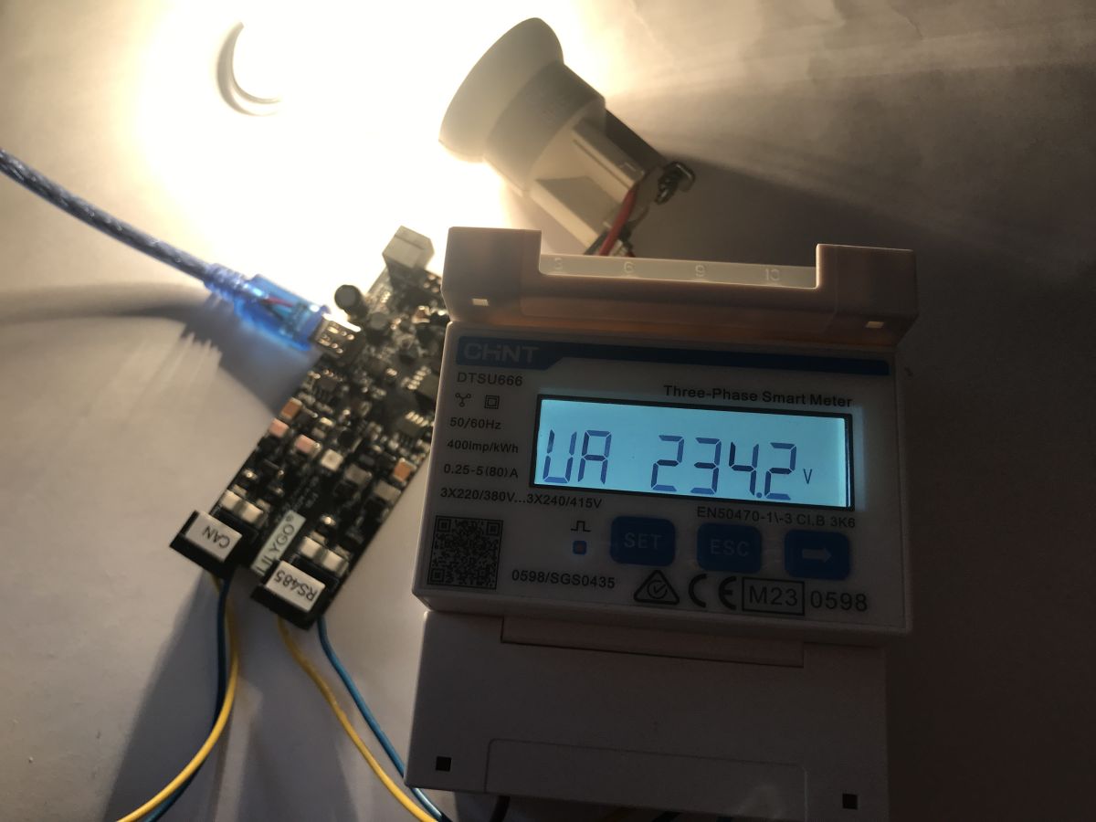
The whole process during testing:
Results on the web:
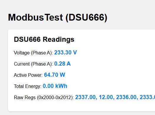
In the same way, you can access other values from the documentation, such as phase current (from 0x200C), total active power (0x2012), power factor (0x202A), total energy consumed and supplied (from 0x101E) or even the mains frequency (0x2044).
Full register table:
| Address | Code | Parameter description | Data type | Length (words) | Read/Write |
| 0000H | REV. | Software version | Signed | 1 | R |
| 0001H | UCode | Programming code (1–9999) | Signed | 1 | R/W |
| 0002H | CLr.E | Energy reset (1: clear energy) | Signed | 1 | R/W |
| 0003H | net | Selection of mains configuration (0: 3-phase 4-wire, 1: 3-phase 3-wire) | Signed | 1 | R/W |
| 0006H | IrAt | Current ratio (1–9999) | Signed | 1 | R/W |
| 0007H | UrAt | Voltage ratio (0.1–999.9) | Signed | 1 | R/W |
| 000AH | Disp | Alternating display time (s) | Signed | 1 | R/W |
| 000BH | B.LCD | Screen backlight duration (minutes) | Signed | 1 | R/W |
| 000CH | Endian | Reserved | Signed | 1 | R/W |
| 002CH | Protocol | Protocol selection (1: DL/T645, 2:n.2, 3:n.1, 4:E.1, 5: o.1) | Signed | 1 | R/W |
| 002DH | bAud | Transmission speed (0:1200, 1:2400, 2:4800, 3:9600) | Signed | 1 | R/W |
| 002EH | Addr | Modbus address (1–247) | Signed | 1 | R/W |
| 2000H | Uab | Phase-to-phase voltage Uab (V, ×0.1) | float | 2 | R |
| 2002H | Ubc | Ubc phase-to-phase voltage (V, ×0.1) | float | 2 | R |
| 2004H | Uca | Phase-to-phase voltage Uca (V, ×0.1) | float | 2 | R |
| 2006H | Ua | Phase voltage Ua (V, ×0.1) | float | 2 | R |
| 2008H | Ub | Phase voltage Ub (V, ×0.1) | float | 2 | R |
| 200AH | Uc | Phase voltage Uc (V, ×0.1) | float | 2 | R |
| 200CH | Ia | Phase A current (A, ×0.001) | float | 2 | R |
| 200EH | Ib | Phase B current (A, ×0.001) | float | 2 | R |
| 2010H | Ic | Phase C current (A, ×0.001) | float | 2 | R |
| 2012H | Fri | Total active power (W, ×0.1) | float | 2 | R |
| 2014H | Pa | Active power, phase A (W, ×0.1) | float | 2 | R |
| 2016H | Pb | Active power, phase B (W, ×0.1) | float | 2 | R |
| 2018H | Pc | Active power, phase C (W, ×0.1) | float | 2 | R |
| 201AH | Qt | Total reactive power (var, ×0.1) | float | 2 | R |
| 201CH | Qa | Reactive power, phase A (var, ×0.1) | float | 2 | R |
| 201EH | Qb | Reactive power, phase B (var, ×0.1) | float | 2 | R |
| 2020H | Qc | Reactive power, phase C (var, ×0.1) | float | 2 | R |
| 202AH | PFt | Total power factor (×0.001) | float | 2 | R |
| 202CH | PFa | Phase A power factor (×0.001) | float | 2 | R |
| 202EH | PFb | Phase B power factor (×0.001) | float | 2 | R |
| 2030H | PFc | Phase C power factor (×0.001) | float | 2 | R |
| 2044H | Freq | Mains frequency (Hz, ×0.01) | float | 2 | R |
| 101EH | ImpEp | Total active energy consumed (kWh) | float | 2 | R |
| 1020H | ImpEpA | Active energy consumed, phase A (kWh) | float | 2 | R |
| 1022H | ImpEpB | Active energy consumed, phase B (kWh) | float | 2 | R |
| 1024H | ImpEpC | Active energy consumed, phase C (kWh) | float | 2 | R |
| 1026H | NetImpEp | Net active energy consumed (kWh) | float | 2 | R |
| 1028H | ExpEp | Total active energy supplied (kWh) | float | 2 | R |
| 102AH | ExpEpA | Active energy supplied, phase A (kWh) | float | 2 | R |
| 102CH | ExpEpB | Active energy supplied, phase B (kWh) | float | 2 | R |
| 102EH | ExpEpC | Active energy supplied, phase C (kWh) | float | 2 | R |
| 1030H | NetExpEp | Net active energy supplied (kWh) | float | 2 | R |
You can also take a look inside the meter:
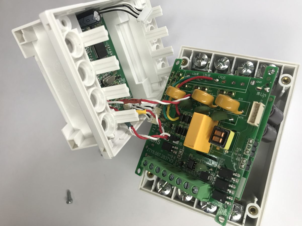

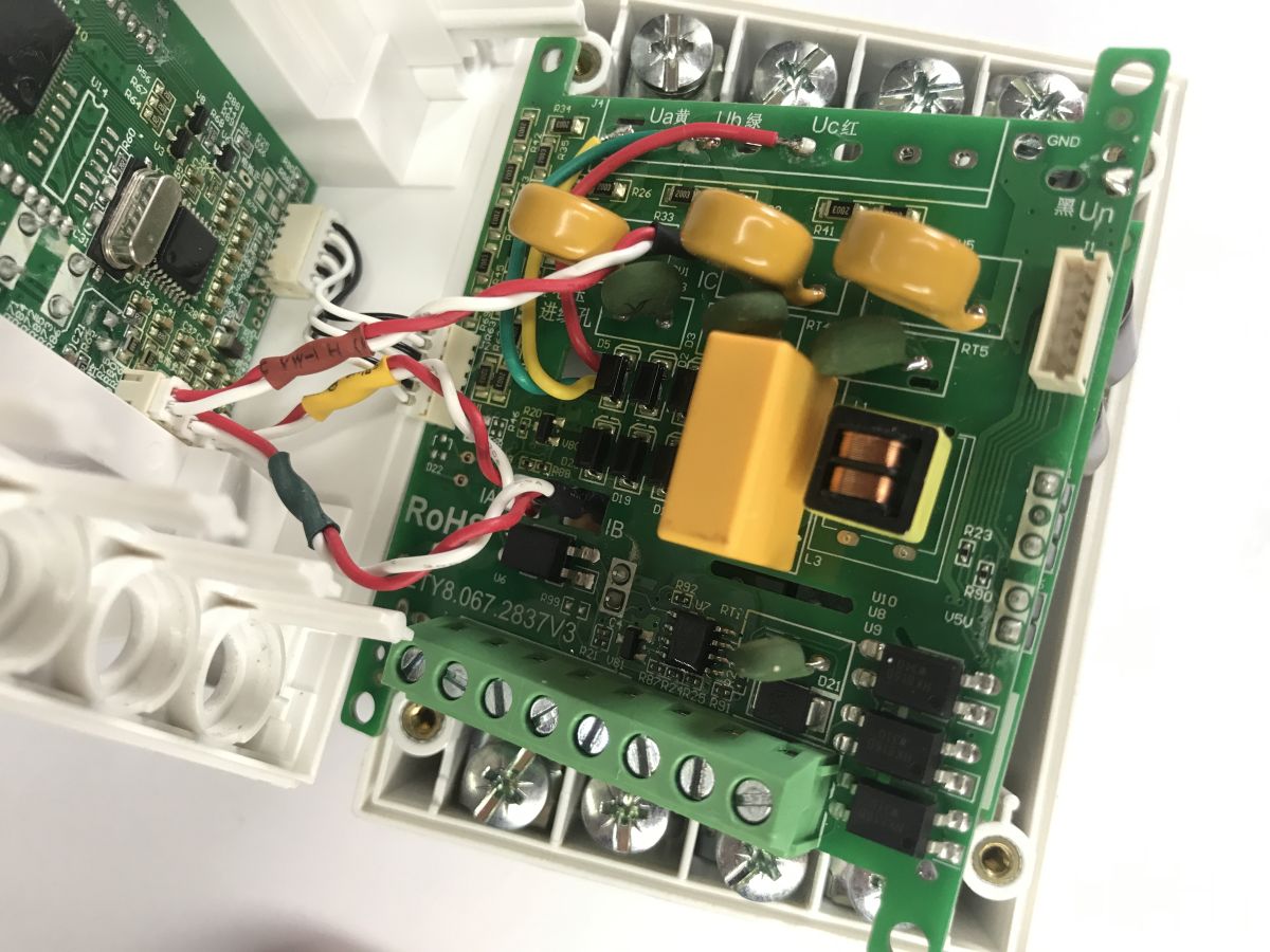
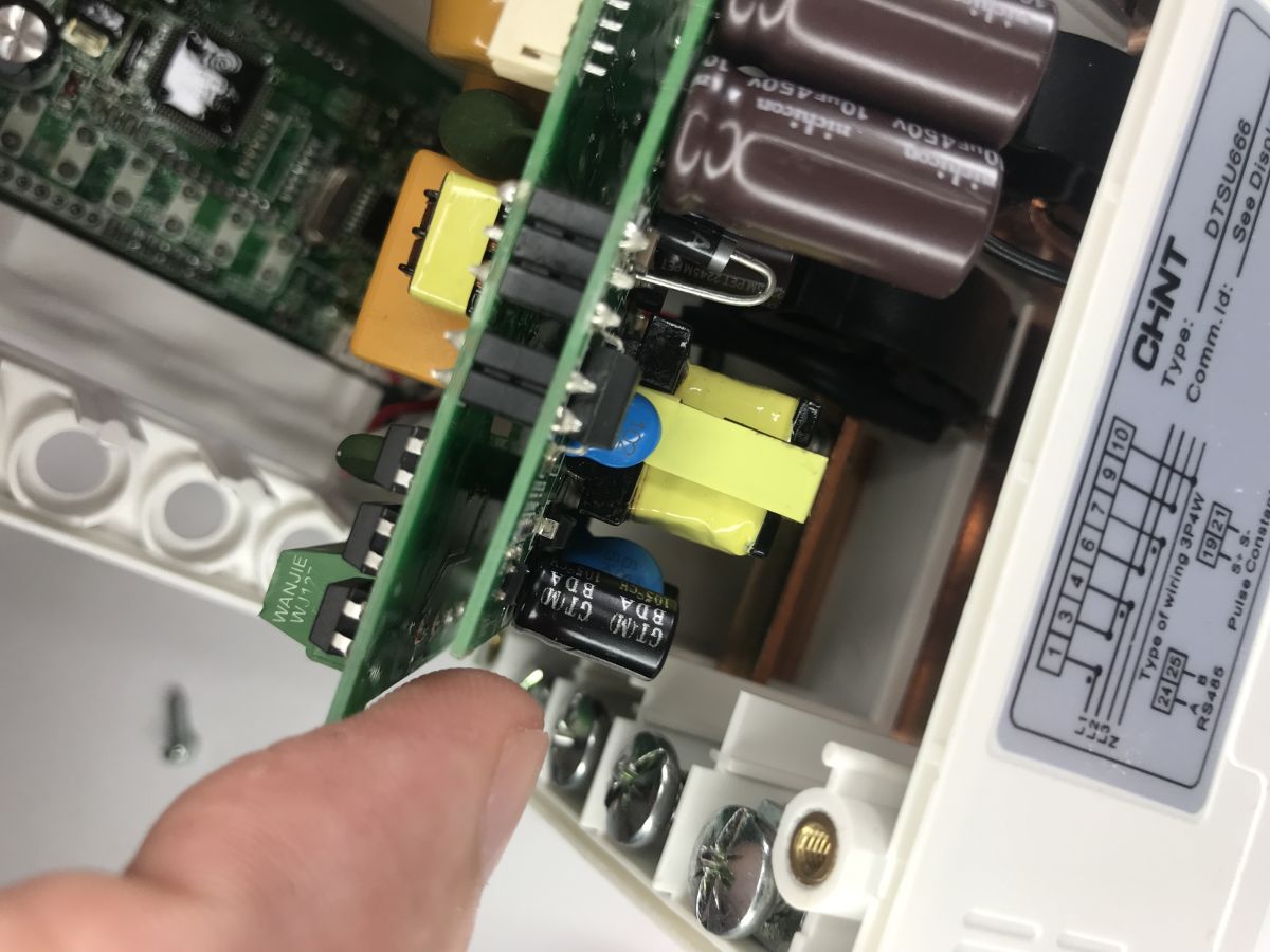
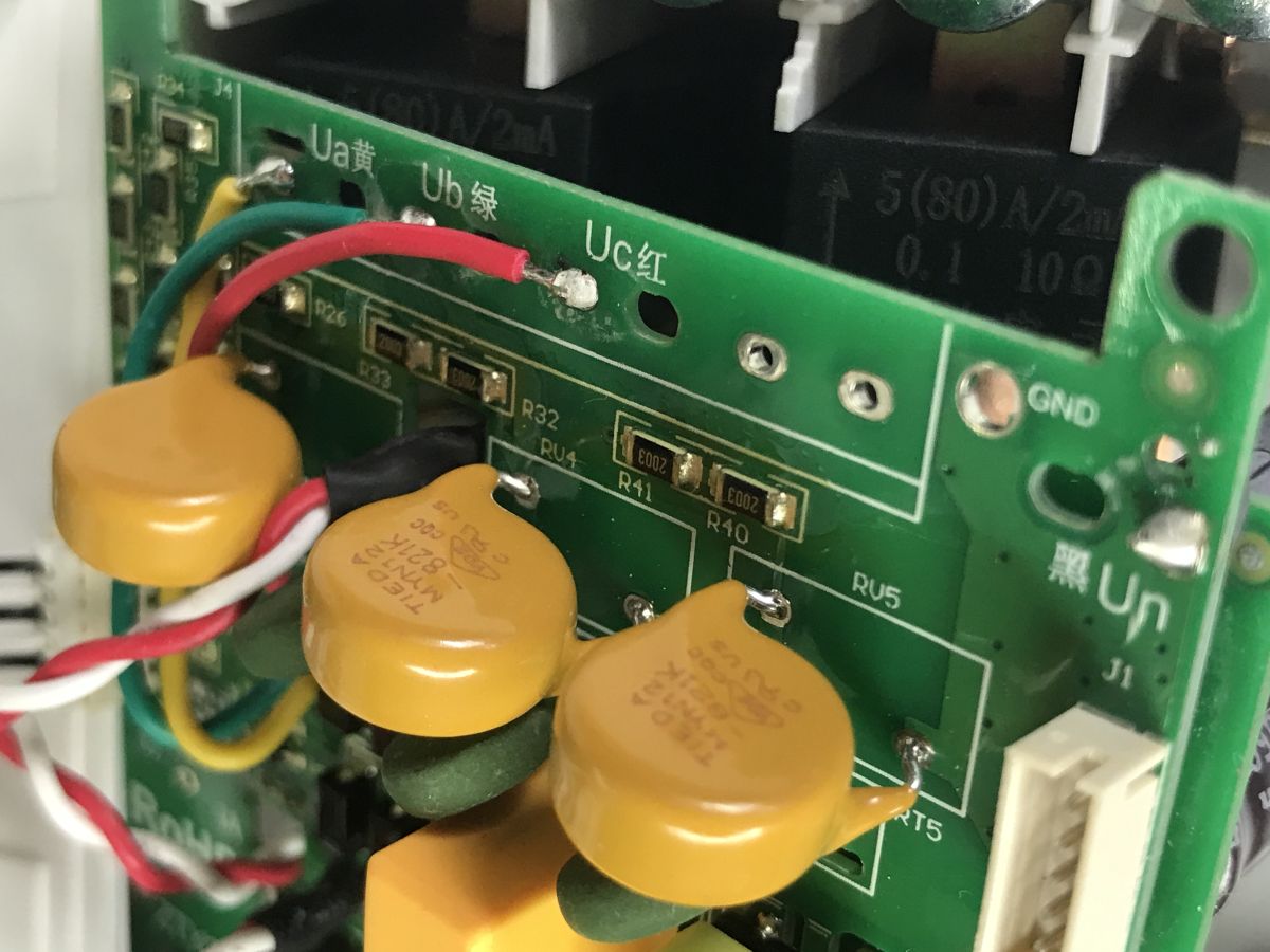
The integrated circuits are unmarked; the board is coated with a layer of varnish for protection. The internal layout appears to be quite elaborate; MYN12-821K varistors can be seen, used for surge protection, along with 5(80)A\2mA current transformers.
In summary, integrating the DTSU666 meter into your own projects relies on handling standard serial communication via an RS485 converter. Thanks to the libraries available for the ESP32, we can handle the Modbus RTU protocol by calling a single function. This enables automated monitoring of network parameters without being locked into a single manufacturer’s closed software ecosystem. We can now freely process the received data and send it on to a display, a database, or perhaps even to Home Assistant.
Do you use energy meters with a Modbus interface?

p.kaczmarek2 wrote 14721 posts with
rating 12806 , helped 659 times.
Been with us since 2014 year.
Comments
This is what it would look like in Python (I don’t have a meter, so I can’t check 100%) Programme functions: Reading all parameters – read_all_data() Reading selected parameters – read_specific_data(['Ia',... [Read more]