Elektroda.com
Elektroda.com
X

Pulse oximeter: measurement of pulse and oxygen saturation of arterial blood

mb1988 74410 36
This content has been translated flag-pl » flag-en View the original version here.
  • Pulse oximeter: measurement of pulse and oxygen saturation of arterial blood

    Hello all.
    I would like to present devices that I and two friends made for the subject of Microprocessor Technology at AGH. At the same time, this and my colleagues' applications will be on display at the Krakow Science Festival on May 14 from 11:30 to 16:00, in the main hall of the A0 building at al. Mickiewicz, so I cordially invite you ;-) .

    :arrow: Principle of operation
    The principle of measuring saturation is based on the fact that oxygenated blood (specifically hemoglobin) absorbs different wavelengths differently. In short, we scan the finger with 660nm and 940nm light, and then we calculate the parameter of interest based on the ratio of the amplitudes of the received signals. The heart rate is calculated based on the time interval between the maxima on the plethysmographic curve.

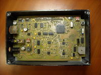
    :arrow: Main board
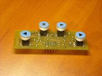
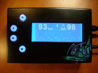
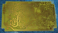
    The system is driven by a 68HC908AB32 microcontroller. Waveforms from the 4-output PWM through a small logical function control the S&H systems and the H bridge switching diodes alternately. The lower transistors in the bridge together with D / A converters are regulated current sources determining the brightness of light pulses. The signal from the photodetector is demultiplexed (red and infrared pulses go to different processing paths), demodulated and filtered. Next, the signal goes to an amplifier with programmable gain to finally be sampled by the transducer contained in the microcontroller structure. The data is presented on a graphic display with 192x64 pixel organization. The keyboard was made on a separate board with illuminated buttons with a label attached to it. These buttons are used to set alarms (pulse decrease / increase, saturation decrease). The whole is powered from a 5V power supply. As you can see in the photo, minor corrections in the schematic diagram were made after soldering the whole :P .
    Pulse oximeter: measurement of pulse and oxygen saturation of arterial blood Pulse oximeter: measurement of pulse and oxygen saturation of arterial blood Pulse oximeter: measurement of pulse and oxygen saturation of arterial blood

    :arrow: Finger sensor
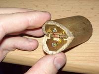
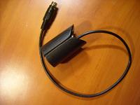
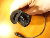
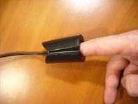
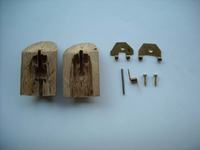
    The finger probe was made of - what can I say - oak style from a shovel :P . The wooden piece was cut in half, then hollowed out on a bench drill. The hinge visible in the photo is a formed piece of a large brass wing hinge. The spring comes from "jaws with teeth" hair clips :P . The cable is a memory of my Logitech UltraX keyboard. In the upper part of the sensor there are 4 diodes - 2 red and 2 infrared ones connected in parallel. In the bottom there is a PIN photodiode. In addition, a piece of sponge has been installed in the sensor, which makes the sensor hold securely on both thin and thick fingers.
    Pulse oximeter: measurement of pulse and oxygen saturation of arterial blood Pulse oximeter: measurement of pulse and oxygen saturation of arterial blood Pulse oximeter: measurement of pulse and oxygen saturation of arterial blood
    Pulse oximeter: measurement of pulse and oxygen saturation of arterial blood Pulse oximeter: measurement of pulse and oxygen saturation of arterial blood

    :arrow: Housing
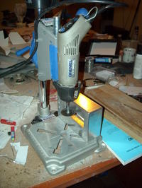
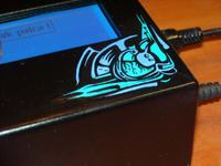
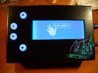
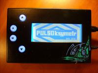
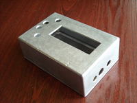
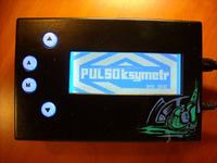
    Due to the fact that the device was intended for a public show, we decided that it should look inviting and distinguish itself somewhat from the usual cold medical equipment. It was made of an aluminum can. The window was cut out with a dremel mounted in a rack. The whole is painted black with a semi-spray. Finally, the graphics were applied with the same hand that adorned the HDDClock standing on my desk ;-) .
    Pulse oximeter: measurement of pulse and oxygen saturation of arterial blood Pulse oximeter: measurement of pulse and oxygen saturation of arterial blood Pulse oximeter: measurement of pulse and oxygen saturation of arterial blood

    Below are some additional photos and a video of the system operation (the alarm was set at 75 beats per minute). For now, I am only providing a schematic diagram (almost final), because the rest of the documentation needs to be worked out before publication. Everyone interesting I invite you once again to the presentation on May 14, and now for discussion.
    Regards :) .
    Pulse oximeter: measurement of pulse and oxygen saturation of arterial blood Pulse oximeter: measurement of pulse and oxygen saturation of arterial blood Pulse oximeter: measurement of pulse and oxygen saturation of arterial blood


    Cool? Ranking DIY
    About Author
    mb1988
    Level 12  
    Offline 
    mb1988 wrote 93 posts with rating 256. Been with us since 2006 year.
  • #2
    parafka
    Level 20  
    Very interesting project. However, I'm afraid that the lack of finger message may slightly distort the pulse rate. :sm31:
    Can you describe in brief why you need to use two wavelengths of light?
    Is one ring not enough?
    Congratulations on successful construction.
  • #3
    Kuniarz
    Moderator of Designing
    An interesting and well-made project, while on the message "NO FINGER" and the icon of a hand without one finger I would think about it :D
    Maybe write something like "put on a sensor" etc.
  • #4
    piotrva
    VIP Meritorious for electroda.pl
    Very interesting design, aesthetically made.
    Could you just include photos of the "mechanism" of the sensor (optoelectronic components)?
    As for the message about the lack of a finger, I have no objections ;-)
    PS. Isn't dr Jacek Kołodziej teaching you?
  • #5
    mb1988
    Level 12  
    The message about the lack of a finger is, say, a student, playful approach to the topic - as I said, the equipment will never go to the hospital :P .

    The measurement is performed for two wavelengths, because it makes the result independent of factors such as skin, bone or dirt thickness on the nail. The signal at the output of the input amplifier for about 2.5V DC and 20 mV Variable. The constant component corresponds to the suppression introduced by bones, tissues, venous blood and non-pulsating arterial blood. Pulsating arterial blood introduces this tiny variable component. In the olden days, when the field was just developing, the measurement was carried out for one wavelength, but this required prior - attention - squeezing the finger so hard that all blood flows out of it, to estimate what suppression is introduced only by the above-described tissues, and only then performed variable component measurement.

    In the afternoon I will upload some additional photos of the sensor. And Mr. dr Kołodziej is one of my leaders among others ;) .
  • #6
    elektronik999
    Level 26  
    parafka wrote:
    Can you describe in brief why you need to use two wavelengths of light?
    Is one ring not enough?

    It is more or less that oxidized blood absorbs one color and blood that has already given oxygen to another.
  • #7
    mb1988
    Level 12  
    Exactly. And based on the analysis of signal amplitudes, we can determine how much percentage of iris blood is oxygenated and how much is not.
  • #8
    tmf
    Moderator of Microcontroller designs
    Great design. I have a technical question - why did you use two separate processing paths? It couldn't be done in one?
    And the second nomenclature note - hemoglobin combined with oxygen is oxygenated hemoglobin - not oxygenated, nor God's oxygenated weapon. Oxidized hemoglobin is methemoglobin - that is, nothing good :)
  • #9
    M. S.
    Level 34  
    How did you scale the oxygen content in your blood? Is this measurement independent of finger "parameters" - skin thickness, cleanliness etc.?
  • #10
    IoNcs
    Level 15  
    Were the measurements compared with other devices of this type?
  • #11
    Anonymous
    Level 1  
  • #12
    mb1988
    Level 12  
    If I would like to use one processing path, demultiplexing and filtration would have to be done after sampling the signal. The applied process is not a signal processor, so applying filters other than moving average becomes a bit troublesome.

    The application was written in such a way that the system adjusts the diode's work point, and the gain in the processing path depending on the thickness of the finger of the examined person.

    The instrument was not calibrated, I only use known empirical relationships. Calibration of the device would require finding a group of volunteers who would first want to test my device, and then donate blood, which will be tested in the laboratory to determine exactly the oxygen content by other methods (judging by the prices of such devices, the costs of obtaining the certificate are not small). The device was also not compared with real pulse oximeters, because I do not have access to such devices. However, on a group of several people that I tested, the result corresponded to a typical for a healthy person, i.e. 95% - 99%. And that my friends didn't look sick ... :P . Remember that this project is intended to illustrate only the idea of measurement and can not be used in any diagnostics.
  • #13
    adamus202
    Level 12  
    And I have a question what is this microcontroller and in what language was the program written for it?
  • #14
    Tomekddd
    Level 23  
    Very interesting device ;) I always wondered how it works. I did a "non-invasive blood flow meter" at the ICU and I also wanted to add something to it, but I didn't know how to build it. Now I know the principle of operation, maybe I will figure something out.

    Heh, what did you do with your pulse so much? :D

    Added after 1 [minutes]:

    I'm also interested in this graphic, is it painted black plexiglass? and highlighted from below?
  • #15
    BartekLecki
    Level 14  
    adamus202 wrote:
    And I have a question what is this microcontroller and in what language was the program written for it?


    This is Motorola, currently Freescale
    http://www.freescale.com/webapp/sps/site/prod_summary.jsp?code=HC08AB&fsrch=1 " target="_blank" rel="nofollow noopener ugc" class="postlink inline" title="" > http://www.freescale.com/webapp/sps/site/prod_summary.jsp?code=HC08AB&fsrch=1

    in what language (C or assembler) must the author already speak ;)

    Very cool design. Congratulations!
  • #16
    mb1988
    Level 12  
    Procek is an 8-bit Freescale CISC microcontroller. The program was entirely written in C.

    The graphics may look illuminated in this light, although this is not the case. It was applied to an already painted box with paints for decorating ceramics.

    As for the irregularity of my heartbeat: especially when recording a video, I would hold my breath at moments to activate the alarm :P . Holding your breath causes a virtually instantaneous marked drop in heart rate.
  • #17
    naelektryzowany
    Level 17  
    Hello, what method were used for the tiles because the effect is phenomenal - no digestion etc.
  • #18
    mb1988
    Level 12  
    Plates made by photochemical method. I used Bungard laminate, factory packed with photosensitive varnish. The mask was printed with an inkjet printer on a specially adapted foil. I used a facial tanning bed for exposure. Exposure time - 4 minutes. In home conditions, it is probably impossible to obtain better quality, and the repeatability of results is almost 100%. Laminate is more expensive, but the plate is ready for pickling after 5 minutes from the moment the mask comes out of the printer, and this is also not without significance.
  • #19
    Taenia_Saginata
    Level 31  
    Have you checked how many you can get down to?
  • #20
    mb1988
    Level 12  
    The device has software limitations and measures heart rate within 35 - 240 beats per minute, and saturation 75% - 100%. However, being healthy, to get a 75% result I would have to hold my breath for about 8 minutes. With my skills I was able to slide at most 2% from the normal result :P .
  • #21
    Galareta
    Level 23  
    If I understand everything correctly, getting the pulse from your finger (ear or something that shines through) is not too much trouble? red diode and photodiode + gain and pulling out of this change in "transparency" of the finger is enough? or would it have to be an infrared diode?

    Ps. I have never been interested in this issue and now that I read it it seems interesting.
  • #22
    mb1988
    Level 12  
    The system for measuring the heart rate itself is much less demanding, because due to the fact that we are only interested in the frequency of the waveform, the signal can be strongly overdriven. In addition, as you have already mentioned, it is enough to use one wavelength (for example 660nm). Virtually all you need is a simple analog front-end. Measurement of saturation, however, requires that the analyzed course be stable and, most importantly, linearly reflect changes in the amount of blood flowing through the arteries.
  • #23
    siejacy_zamet
    Level 12  
    Dear friend! Dr Wiśniewski will make you happy! HC08 is not RISC-i, but CISC-i. And the easiest way to find out about this is by programming them in assembler, as you can see you didn't have the courage (it would be another spectacular asset of the device). Good luck on your presentation! I remember that when I was doing it a few years ago in Odlewnik, there were crowds of testers and clickers.
  • #24
    mb1988
    Level 12  
    Already corrected :P . In assembler I wrote an earlier small project and judging by how I was doing this project I would probably finish in spring, but in 2020 :P .
  • #25
    Xitami
    Level 29  
    Make: DIY Pulse Oximeter
    Polish engineering student mb1988mb1988 and two friends built this homebrew pulse oximeter. It measures oxygen saturation in a patient by shining two wavelengths of light (infrared and red) through their finger, and recording the changes in light transmission over time. To power it all, they are using an 68HC908AB32 processor...
  • #26
    ladamaniac
    Level 39  
    Unfortunately, I had the trouble to use a pulse oximeter. To check the calibration of factory sensors there are "artificial fingers" with specific saturation. The cost of the Nonin FlexiWrap factory sensor is some 500 zlotys a few years ago.
  • #27
    ewilman
    Level 1  
    And any supporting literature while carrying out the project? I am interested in this method of measuring saturation.
  • #28
    stefanino
    Level 1  
    Hi guys
    do you know if it's possible to find a translation from polish to english for the great post of Mb1988 "Pulsoksymetr: pomiar tętna i nasycenia krwi tętniczej tlenem"?

    I am working on a similar objet for an installation I've made, I am developing a new one with a homemade sensor (thanks to Vladimir, of course)
    More info here: http://vimeo.com/10609154

    thank you a lot


    Stefanino
  • #29
    marcelix007
    Level 14  
    mb1988 wrote:
    If I would like to use one processing path, demultiplexing and filtration would have to be done after sampling the signal. The applied process is not a signal processor, so applying filters other than moving average becomes a bit troublesome.

    The application was written in such a way that the system adjusts the diode's work point, and the gain in the processing path depending on the thickness of the finger of the examined person.

    The instrument was not calibrated, I only use known empirical relationships. Calibration of the device would require finding a group of volunteers who would first want to test my device, and then donate blood, which will be tested in the laboratory to determine exactly the oxygen content by other methods (judging by the prices of such devices, the costs of obtaining the certificate are not small). The device was also not compared with real pulse oximeters, because I do not have access to such devices. However, on a group of several people that I tested, the result corresponded to a typical for a healthy person, i.e. 95% - 99%. And that my friends didn't look sick ... :P . Remember that this project is intended to illustrate only the idea of measurement and can not be used in any diagnostics.


    I do not quite understand why it would not be better to do filtering in one track and then split into two lines (directly connect two capacitors C16, C40 to AD8542)?
  • #30
    mb1988
    Level 12  
    Hmm, and how does a friend imagine analog filtering of two time-multiplexed signals without separating them first?