logo elektroda
logo elektroda
X
logo elektroda

CH341 à la Bus Pirate - cheap and moderately useful

ostrytomasz 4167 10
ADVERTISEMENT
Treść została przetłumaczona polish » english Zobacz oryginalną wersję tematu
📢 Listen (AI):
  • Screenshot of the CH341 application displaying measurement options .

    I would like to present an application that is a collection of test tools using CH341 as a physical interface.

    The original purpose of this application was to repair laptop batteries.
    However, I had to familiarise myself with the CH341 chip beforehand, I started with more elementary functions like I2C support and the application took the form of a collection of loosely related modules.
    Programming the smart battery turned out to be more complicated than I expected and, given that I only have a few such batteries, I stopped at reading their parameters for the time being.
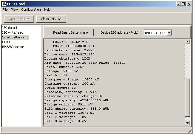
    Screenshot of CH341A Tool application showing smart battery information. .

    What emerged from this, however, was a tool with a wider range of functions, reminiscent of Bus Pirate.

    Currently (version 1.04) funcionality includes:
    - detection of I2C devices
    - writing/reading raw data using I2C, SPI
    - smart battery status reading
    - sensor support: BME280/BMP280, Si7021, BMP180, SHT11, LM75, AHT10/AHT20, AS5600, APDS-9960, L3G4200D, BMI160, MPU6050, VL53L0X
    - support of displays: HD44780 directly and via PCF8574, SSD1306, MAX7219 8x8 LED, CH455 LED from a DVB-T decoder
    - support for Si5351A generator
    - support for FM tuner RDA5807M
    - support for RTC DS1302 and DS1307
    - support for the MCP4725 DAC and ADC ADS1115
    - read/write of ETH PHY registers via MDIO interface (Clause 22 + MMD)
    - support for Ethernet cable length measurement function via LAN8742 (TDR + CBLN)

    Some screenshots and photos:
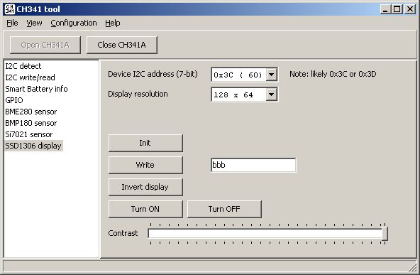
    Screenshot of the CH341 tool application interface for managing I2C devices. .
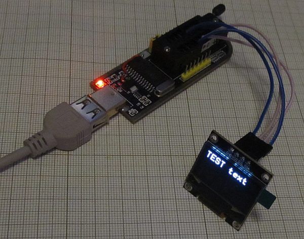
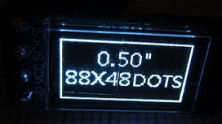
    CH341 module with OLED display showing text. .
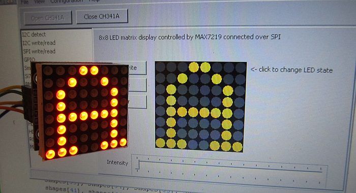
    8x8 LED matrix controlled by MAX7219 with application on screen .
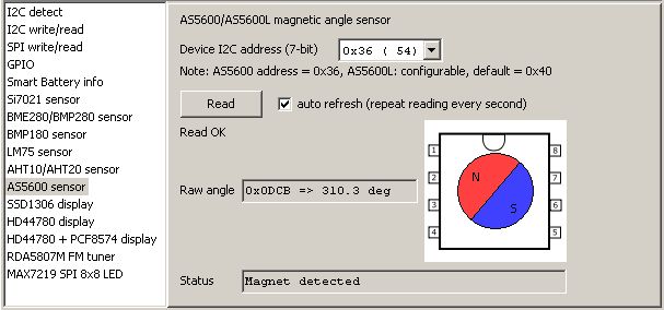
    Test application interface with CH341 chip supporting AS5600/AS5600L sensor .
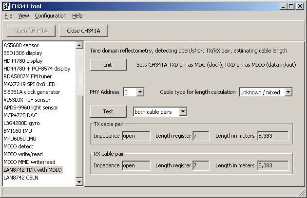
    Screenshot of the CH341 tool application with user interface. .

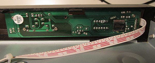
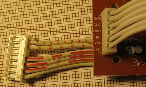
    I found out about the CH455 LED and keypad controller from the topic https://www.elektroda.pl/rtvforum/topic4066595.html, but in my case the "donor" was a WIWA HD-102 (burnt out power supply even before switching to DVB-T2) in which the display with the controller is placed on a separate board connected by tape.
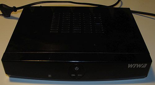
    Black WIWA HD-102 set-top box with power button and channel buttons on the front panel. .
    Close-up of a circuit board controller with a ribbon cable. .
    LED display module with buttons and electronic components. .
    Close-up of a circuit board with an integrated circuit and tracks. .
    Close-up of a circuit board with attached wires. .
    Curiosity: clearly "burnt" segments of the display where "C" was displayed as "CHANNEL":
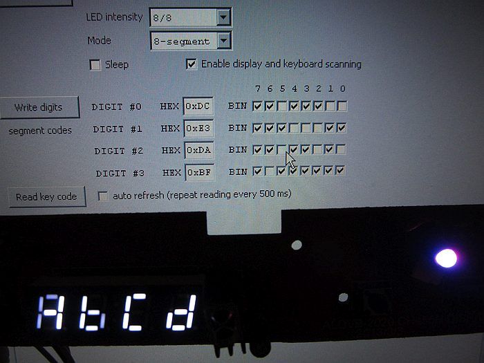
    Segmented LED display and application interface with segment settings. .

    This is already most of the electronic trinket I have that can be handled.
    I have omitted the typical use of the CH341A as a serial memory programmer, as there is already quite a selection of software supporting this.
    To the best of my knowledge, the limitations and shortcomings (limited SPI speed, irregularity of the UART output waveform for higher speeds) of the CH341 will not allow the implementation of 1-wire or the WS2812 protocol.
    Support for a given chip is most often limited to basic or selected functions, allowing testing but not necessarily giving access to all capabilities.
    Much of the source code comes from other open source projects, but I stick to licences that would not introduce problems for commercial use.

    For a slightly longer description: https://tomeko.net/software/CH341A_tool/.
    Attached: source code (Turbo C++ 2006, one of the ancient versions of C++ Builder) and executable file.
    The application only works under Windows x86 or x64, it does not work with Windows ARM or Wine.
    It is required to install the driver "CH341PAR" (if the CH341 was used as a programmer, this driver is probably already installed), the application will not run without it..

    Cool? Ranking DIY
    About Author
    ostrytomasz
    Level 24  
    Offline 
    ostrytomasz wrote 464 posts with rating 179, helped 77 times. Been with us since 2004 year.
  • ADVERTISEMENT
  • #2 21514734
    RomanWorkshop
    Level 14  
    A simple, small, multi-purpose and multi-purpose programmer - these are the kind of tools that prove most useful. I have suggestions for changes/improvements:

    1. the scanner could scan the entire address range of devices on the I2C bus ($00-$7F) and present the result in graphical form - the detected device denoted by a given symbol, placed in the corresponding 0-7 row and 0-F column. This kind of presentation is clear and allows you to quickly determine the addresses of detected devices. I used it myself in my scanner ( Link ).

    2. an option could be added to the program to identify the type of OLED display driver (SSD1306/SH1106/SH1107), based on the identification value read from its status register (status register, address $00). This detection method uses the "ss_oled 4.3.1" library for Arduino ( Link ). The first read of the status register may fail (for example, this is the case with the SH1106 controller), but the second read always returns the correct value.
    The documentation of the SSD1306 controller does not contain a description of the identification value returned (all bits "Reserved"), and also informs that it is not possible to read this register via the serial interface (I2C). Nevertheless, it can be read along with an undocumented identification value, from which the type of display driver can be determined. The returned values are (lower 6 bits): $03/$06 = SSD1306, $07/$0F = SH1107, $08 = SH1106. Additionally, some of the new 128x32/128x64 OLED display modules I currently have return values of: $02/$04 - according to my information and practical experience, these indicate an SSD1315 controller completely compatible with the SSD1306. I'm also curious as to what value a display with an SSD1309 driver returns - I'll check this as soon as I get my hands on one.
  • ADVERTISEMENT
  • #3 21514795
    ostrytomasz
    Level 24  
    RomanWorkshop wrote:
    1. The scanner could scan the entire address range of devices on the I2C bus ($00-$7F) and present the result in graphical form - the detected device denoted by a given symbol, placed in the corresponding row 0-7 and column 0-F. This kind of presentation is clear and allows you to quickly determine the addresses of detected devices. I have used it myself in my scanner (Link).
    .

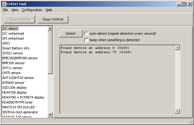
    It does indeed fit very nicely on a small graphical display (and the Linux i2cdetect presents it similarly), but I think the text form is more practical in this case. As I look at it now, it would be possible to add a value in binary form for convenience, because sometimes that's the only thing in the documentation (I just happen to have a pdf of the MAX11601 in front of me) and I myself have sometimes got stuck by confusing 7- and 8-bit conventions.

    Screenshot of CH341A tool showing an interface for detecting I2C devices. .

    I used to think about trying to detect the type of chip based on an address (or set of addresses), but the effectiveness and, above all, the desirability of this seems debatable to me at the moment.
  • #4 21514879
    RomanWorkshop
    Level 14  
    ostrytomasz wrote:
    This does indeed fit very nicely on a small graphical display (and is similarly presented by the Linux i2cdetect), but I think the text form is more practical in this case.
    .
    You could always add a switch of how the detected devices are presented, as both can be useful in practice.

    ostrytomasz wrote:
    I used to think about trying to detect a circuit type based on an address (or set of addresses), but the effectiveness and above all the desirability of this seems debatable to me for now.
    .
    Detecting a particular chip just based on its address is not possible, because many of them use the same addresses. The author of the library Bit Bang I2C recognises a specific device based on its address and the values read from its specific registers. Such detection makes some sense, but only for the most popular chips/sensors. By the way, I've started making a simple database of I2C chip/device addresses - I'm somewhere in the middle of the current offerings from one of the chip companies and already have over 300 chips. I wonder how many chips with an I2C interface have been produced in the world so far? Probably going to be a couple of thousand, which means I'm still a bit down ;) .
  • ADVERTISEMENT
  • #5 21515097
    mrtip
    Level 14  
    >>21514879 .
    Number of unique IC models with I²C interface , i.e. how many different chips (EEPROMs, sensors, RTC clocks, etc.) have been created with I²C support .

    📌 How do you estimate this? .

    1. I²C is a very popular interface - from the 1980s until today.
    Circuits with I²C were and are made by companies such as:
    - NXP, ST, Microchip, Texas Instruments, Analog Devices, Maxim, Infineon, OnSemi, Renesas and hundreds of smaller ones.
    - Chinese manufacturers have added a huge number of low-cost models in the last decade: CJMCU, GY-series, DFRobot, Waveshare, etc.

    2. Types of circuits with I²C: .
    - EEPROM (e.g. 24C02, 24C256)
    - RTC (DS1307, PCF8563)
    - ADC/DAC (e.g. PCF8591, MCP3424)
    - Sensors (BMP280, BME680, TSL2561, MPU6050, SHT21, VL53L0X...)
    - GPIO expanders (MCP23017, PCF8574)
    - Audio converters, microcontrollers with I²C slave, LED drivers (e.g. PCA9685), battery controllers, medical and automotive sensors, etc.

    📈 Estimate: .
    If we assume:
    - 40+ years of development
    - Every major manufacturer could release hundreds to thousands of models with I²C
    - Hundreds of companies + new chip versions/revisions (sometimes one chip has 10-20 variants)

    🔢 Conservative estimate: .
    - At least 50,000-100,000 unique circuit models with I²C have appeared over the last 4 decades.

    ✅ Answer:

    > There are probably over 50,000 different models of integrated circuits with I²C interface produced worldwide, and the number is still growing.
  • #6 21519538
    rb401
    Level 39  
    ostrytomasz wrote:
    Support for a given system is most often limited to basic or selected functions, allowing testing but not necessarily giving access to all capabilities.
    .

    Right. Your program is good for quick component tests, without the need to compile examples from Arduino for example.
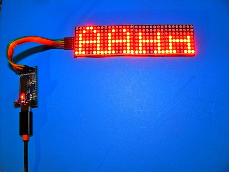
    Just now I checked a 4xMAX7219 display I bought from the Chinese with your program and the result seemed strange at first glance:

    4xMAX7219 display showing HMMM with a controller. .

    But after looking into the DS of this MAX, it came out that everything is as ok as it should be.

    It's also cool that your programme is growing.


    There is one problem with this topic though, that the CH341A is associated with these particular memory programmer boards. Which are simply faulty by design and the first action after purchase is to cure them. I see from the pictures that your board is also corrected.
    But I would like to point out here that for use as a component tester with your software, CH341A boards are more suitable, but in the version without ZIF socket. For example such as I use myself.
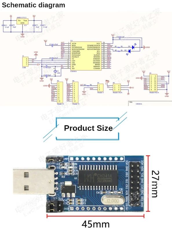
    Here it is with a little unclear schematic, but I could not find a better one:

    Schematic of the CH341A circuit and its dimensions. .

    Switching the logic and power supply voltages of the circuit under test (3.3V, 5V) is correct and convenient. The rest of the features in use as a tester, are the same as this unfortunate programmer board.
  • ADVERTISEMENT
  • #7 21519697
    ostrytomasz
    Level 24  
    rb401 wrote:
    .
    Just now I was checking a 4xMAX7219 display I bought from the Chinese with your program and the result seemed strange at first glance:
    .

    I haven't thought about series bonding unfortunately - I only have one piece for now. Looks like an empty byte needs to be added on the transitions.

    rb401 wrote:
    .
    There is one problem with this topic though, that the CH341A is associated with these particular memory programmer boards. Which are simply faulty by design and the first action after purchase is to cure them. I see from the pictures that your board is also corrected.
    But I would like to point out here that for use as a component tester with your software, the CH341A boards are more suitable, but in the version without the ZIF socket.
    .

    I plan to add one to my next order from ali too - a bit as a spare, a bit for convenience and availability of (I think) all pins.

    Interestingly, I've come across a strong opinion ( https://www.youtube.com/watch?v=J8-Sh7DjiXw ) that conversion to 3.3V is not necessary due to the limited current capacity of the pins. I wouldn't put my head under it myself (not all the pins have been tested, it's impossible to comment on all the circuits in the world), but I did use the programmer for a while without a rework.
  • #8 21520135
    rb401
    Level 39  
    ostrytomasz wrote:
    I haven't thought about linking in series unfortunately - I only have one piece so far. It looks as if you need to add an empty byte on the transitions.
    .
    This is not a nuisance. You only need to additionally press the Write key once so that those words left in the shift registers of the previous cubes reach those cubes displaying the incomplete image and it is ok.

    So it is perfectly possible to test such multiple displays with your program.
    It is just a matter of not immediately panicking when you see missing lines on the right-hand displays that maybe the Chinese have inserted the LED matrix wrongly in the socket or have not soldered something in.

    But in fact, adding some No-Op (i.e. e.g. 16 zero bits) at the end of each transfer would probably not hurt and would eliminate this effect.
  • #9 21524935
    Michal2002
    Level 24  
    Cool toy :) Merry Christmas Resurrection.
  • #10 21569159
    George54351
    Level 6  
    I am wondering about CH341 if it could do some EMMC programming as an alternative and cheap solution to large,professional and a lot more expensive programmers.Maybe i am totally wrong since i dont have encountered EMMC programming in the past and i dont have a programmer that can handle the job yet.
  • #11 21569251
    ostrytomasz
    Level 24  
    George54351 wrote:
    CH341 whether it could do EMMC programming as an alternative and low-cost solution for large, professional and much more expensive programmers


    If speed is what matters, it would be very unattractive due to the severely limited SPI speed, limited USB Full Speed and the need for polling. Any dedicated USB-SD adapter would be many times better. For a multiple programmer, you could look for a microcontroller with 4 SD and Ethernet controllers or USB HS.

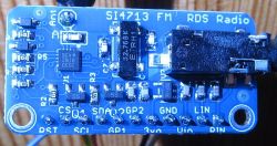
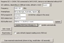
    List of changes in version 1.5.0:
    - added ADC MAX11601
    - Added TEA5767 FM tuner
    - Added RTC S35390A
    - RTC DS3231 added
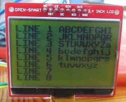
    - added LCD display ST7567
    CH341 à la Bus Pirate - cheap and moderately useful
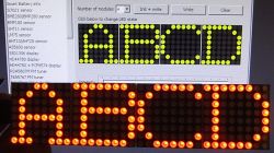
    - added support for cascaded 8x8 LED displays with MAX7219 (up to 4 units)
    CH341 à la Bus Pirate - cheap and moderately useful added magnetometer/computer HMC HMC.
    - added HMC5883L magnetometer/compass
    - added INA226 power monitor
    - added presentation style selection (list or "i2cdetect") to I2C device detection module
    - CH341 is reinitialised automatically if I2C speed is changed in settings
📢 Listen (AI):

Topic summary

A software tool utilizing the CH341 chip as a physical interface was developed initially for laptop battery repair but evolved into a multi-functional test suite similar to the Bus Pirate. Current features (v1.04) include I2C device detection, raw data read/write via I2C and SPI, smart battery status reading, and sensor support. Suggestions for improvement include graphical I2C address scanning and OLED driver identification (SSD1306, SH1106, SH1107) based on status register reads. The challenge of identifying chips solely by I2C address was discussed, noting many devices share addresses, and detection often requires reading specific registers. The extensive variety of I2C devices from manufacturers like NXP, ST, Microchip, and Chinese brands was highlighted, covering EEPROMs, RTCs, ADC/DACs, sensors, GPIO expanders, and more. The CH341A board's hardware design issues were noted, recommending versions without ZIF sockets for component testing. The program supports testing cascaded MAX7219 LED displays and various added modules in version 1.5.0, including ADC MAX11601, TEA5767 FM tuner, RTC S35390A and DS3231, ST7567 LCD, HMC5883L magnetometer, and INA226 power monitor. CH341 limitations for high-speed tasks like eMMC programming were acknowledged due to limited SPI speed and USB Full Speed constraints. The software offers selectable presentation styles for I2C detection and automatic CH341 reinitialization on speed changes.
Summary generated by the language model.
ADVERTISEMENT