logo elektroda
logo elektroda
X
logo elektroda

Illuminophony, or a return to the past in a different edition.

efi222 4140 31
ADVERTISEMENT
Treść została przetłumaczona polish » english Zobacz oryginalną wersję tematu
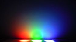
  • Three LED spotlights in red, green, and blue illuminating a wall, blending in the center. .

    Before publishing, I wondered if anyone else was interested in this topic. But maybe there is still a maniac for flashing lights :) .
    Illuminophony - a somewhat forgotten topic. The device has, in my opinion, undergone a backward evouluation and at the outset let me quote my colleague @Preskaler who wrote 20 years ago:

    The idea of illuminophony originated in the 18th century and consisted of casting coloured light on a screen depending on the content of particular frequencies in the music. Low tones corresponded to red (also low frequency) medium tones were green and blue tones were high. These were the beginnings of RGB! Listening to music in this way, that during its amplitude changes of individual frequencies, the listeners simultaneously saw colours changing, dimming when the music was quiet and brightening when the music was strong, and in addition with changing colours across the spectrum. This gave an enhanced artistic experience and the listeners were delighted. Of course, this was done by hand. Modern illuminophony has an excellent tool for this purpose but, unfortunately, the whole principle of this illuminophony has been neglected. What has appeared is a colourophone with three mercilessly flashing lights. This does not give the effect of mixing colours and creating resultant colours, thus making the effect negligible. It is no wonder that it is not clear why there is a division of the acoustic frequencies and even of the three spotlight colours?

    another post in that thread confirms @Preskaler's argument :)
    source: https://www.elektroda.pl/rtvforum/topic190754.html#928465

    I did the project at the request of a colleague. Unfortunately not completed due to undecided periphery (executive headlights).
    The main idea was to simulate the inertia of the bulb filaments. Unfortunately simple circuits using LEDs do not provide smooth modulation of light only, they work zero-one.

    My design is an attempt to meet this challenge.
    I have abandoned analogue filters in favour of a fast Fourier transform (FFT). This simplified the electronics layout considerably.
    To do this, I used the powerful and inexpensive ESP32 MCU and the arduinoFFT.h library

    Device features:
    Three RGB channels.
    9 bit PWM controlling the LED, exponentially modulated in 64 levels.
    LED brightening and dimming inertia setting for each colour. Lovers of 'nystagmus' can set zero.
    Atomatic level for each channel.
    Free frequency (stripe) allocation for each channel.
    Enabling or disabling LED glow in the absence of an audio signal (PWM = 1).
    Unfortunately, the device did not get a UI and the settings have to be changed in program code.

    Program description:
    Program written in Arduino IDE.
    For the purposes of the FFT, 512 samples are taken at a sampling frequency of 40kHz.
    With these parameters, the bar value is approximately 78Hz.
    The audio samples and FFT calculations are performed in the main loop.
    It takes approximately 16ms to take a set of samples and calculate the FFT.
    In the timer interrupt, the PWM LED waveform is modulated.

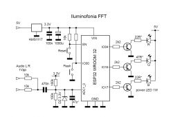
    In the prototype circuit I have used a 1W power LED. Of course, this part can be freely extended.
    I attach a schematic with the development circuit. For the development board, the 3.3V stablizer circuit and the Flash and Reset buttons must be omitted.
    The circuit can be assembled "on your knee" within an hour.
    Good luck with your experiments :) .

    Example settings:

    Increased light incidence:


    .
    Settings for "optical sprinters" (pure PWM): ;) .
    And so it is better than switched LEDs.


    .
    Diagram:
    Diagram of a photophonic device using ESP32 and FFT. .

    Cool? Ranking DIY
    Do you have a problem with Arduino? Ask question. Visit our forum Arduino.
    About Author
    efi222
    Level 19  
    Offline 
    efi222 wrote 528 posts with rating 961, helped 6 times. Live in city Toruń. Been with us since 2019 year.
  • ADVERTISEMENT
  • #2 21489719
    Preskaler
    Level 40  
    @efi222 Congratulations on making this device. However, I was concerned with colour mixing and not flashing three separate colours. Colour mixing as it is, for example, on an LCD screen. Then there is no flashing, but rather a uniformly pulsating resultant colour, arising from the R/G/B ratio, whose brightness is proportional to the amplitude of the voltage at the individual frequencies emitted by the filters (low-pass, band-pass, high-pass). This can also be done with a projector, in which the individual pixels in the three channels (RGB) are independently controlled by filtered tones. It is also possible to project images from three reflectors onto a screen (or matte) but through 3 lenses and in such a way that the 3 colour patches overlap. Then you will get all the colours (purple, red, orange, yellow, green, peacock and blue).
  • #3 21489740
    efi222
    Level 19  
    This is a prototype. We have an RGB output. Further you can do whatever you want with it. You can mount the Led more point-wise. I focused more on the smooth modulation of the light. Nothing prevents you from projecting this light even on the wall.
    But there is already a substitute for mixing. This is difficult to capture on film. I've struggled to film it reasonably correctly at all. Thanks for the response :) .

    Added at 8 [minutes]: .

    In Wojciechowski's book "Modern Toys" there was this illumination on incandescent lamps with projection onto a screen.

    Added after 22 [minutes]:

    So it occurs to me now that mixing RGB colours in a simple way can probably be done on RGB LED tape.
  • ADVERTISEMENT
  • #4 21490132
    Preskaler
    Level 40  
    Sixty-plus years ago I did the blending on three bulbs painted with transparent spirit varnish and placed behind a milky glass. The bulbs were as close together as possible and placed some distance from the matte, in a dark room they gave a blending effect. Nowadays, a single RGB diode placed a short distance from the milky glass will give a much better effect. There is only the problem of controlling it so that it produces linear changes in brightness as a function of the voltage controlling it. Changes in current will not help much either, because its brightness is not linear as a function of current. Unless, perhaps, there are such diodes? It would be much better to achieve such an effect on an LED matrix (LCD, QLED, etc.). Maybe use a ready-made monitor with RGB input?
  • #5 21490148
    efi222
    Level 19  
    LEDs, unlike incandescent bulbs, are not suitable for voltage control. The current characteristics are too steep. About the linearity of the luminosity of such a solution I will not even mention. (Most simple illuminophones work this way).
    In the presented device, the LEDs are controlled by changing PWM depending on the amplitude of the audio signal.
    Led brightness with such control is practically linear in relation to the PWM filling.
    In addition, this characteristic is bent exponentially due to the logarithmic perception of light by our eyes.
    Exponential changes in light with logarithmic vision give visually linear changes.
    In my spare time I might experiment with light projection.
  • #6 21490169
    miroskop
    Level 23  
    I tried to compile the sketch but there are errors of missing declaration: adcAttachPin, timerAlarmWrite, timerAlarmEnable and some more errors.
    What am I doing wrong? The board I have chosen is the ESP32C3 Dev Kit.
  • #7 21490215
    efi222
    Level 19  
    ESP32 C3 is a rather different architecture to ESP32 Wroom (ESP32 Dev Module). The code may not compile for this module.
    At the very top of the source code the requirements for correct compilation are given.
  • #8 21490237
    miroskop
    Level 23  
    I had to roll back the version of "ESP32 by Espressif System" from 3.0.7 to 1.0.4 for the sketch to compile. Selected "ESP32 Dev Module" board.
  • #9 21490287
    efi222
    Level 19  
    Exactly as it is in the description.
    1.0. 4 is the latest version where you can sample the ADC 40kHz and above. In all higher ones the maximum frequency at the ADC input is 10kHz. At least in Arduino core.

    Added after 6 [hours] 20 [minutes]: .

    @Prescaler. I increased the inertia of the lights further. I positioned the LEDs close together. I projected the light onto a white background.
    And something like this came out :) . This is difficult to film. The eyes see differently and the camera exposure differently. Such light projection probably needs to be calibrated. With three colours of the same light intensity there should be white light?


    .
  • #10 21491137
    Preskaler
    Level 40  
    For me "the bomb"! A really great job. White light will be difficult to achieve, because in this way of mixing there will always be unevenness in the individual colour beams and colour spots will appear. However, this is not a problem as it is only a matter of artistic impression.
  • #11 21491758
    LEDówki
    Level 43  
    How does it work driven by "Enola Gay", "Take On Me" and "Gimme All Your Lovin'"?
  • #12 21491770
    efi222
    Level 19  
    On which settings? I can fire it up in the evening.
  • #13 21491776
    LEDówki
    Level 43  
    And how it comes out better there. I won't guess whether with high or low inertia.
  • ADVERTISEMENT
  • #14 21491900
    vodiczka
    Level 43  
    Preskaler wrote:
    60+ years ago I did the mixing on three bulbs painted with transparent spirit varnish and placed behind milk glass. The bulbs were as close together as possible and placed some distance away from the matte, in a dark room they gave a stirring effect
    I did something similar and at a similar time but I placed the bulbs in my parents' large, deep-cut crystal vase. The wall of the vase was about 25 mm thick.

    efi222 wrote:
    I further increased the inertia of the lights. I positioned the LEDs close together. I projected the light onto a white background. And something like this came out
    Super came out.
  • #15 21491938
    efi222
    Level 19  
    I can see that those interested in the device are of an older vintage. Not surprisingly, anyway. When the word "illuminophony" is said, the younger generation makes big eyes. Some try to analyse it....
    I'll just add that the cost of this project, as it stands (development module) should close at around 20pln. With the development board a little more.
    Only minimal knowledge in programming is required to adjust the values of several variables according to yourself. But for this, you do not have to fight with analogue filters.
  • #16 21491954
    LEDówki
    Level 43  
    In Radioelektronik and Praktyczny Elektronik there were diagrams of such colourophones/colorophones :) . In Młody Technik there was a micro-luminophone - three or four transistors and attached to them each a 20 mA diode. It flashed like this.
  • #17 21492006
    Preskaler
    Level 40  
    LEDówki wrote:
    .
    .... It flashed just so.
    .
    That's right - it flashed. The effect is only satisfactory if the colours are mixed.
    I "discovered" illuminophony in 1962 in an article from the magazine "Yunyj Tiochnik" (the Russian equivalent of our "Young Technician"). It referred to the interplay of nerve centres in the human brain between the sense of sight and hearing. This relationship was supposedly discovered as early as the 18th century. Indeed - the sensations are very pleasant.
  • #18 21492493
    LEDówki
    Level 43  
    But then there were no blue LEDs. So there was red, green and yellow. The Colorofon C23B also had these colours and on the wall the light mixes, but the effects are not like RGB mixing. That's what they did, that's what I bought, I'm not going to rework. Some people find these lights laughable. You have to do a bit of work to get the light pulsations to match the music. Not everyone understood this and disco-goers remembered that the lights should be on all the time.... This has no effect. As you can see, not everyone understands that red is supposed to react to bass, green to midrange, yellow/blue to treble. For them, it's supposed to blink and that's it.
  • #19 21492550
    efi222
    Level 19  
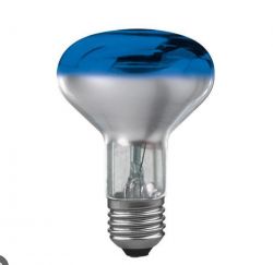
    The first illuminophony I made also had a yellow filter instead of blue. It wasn't until years later that incandescent bulbs with reflectors and coloured filters appeared. Also with blue.
    And whether it should flash sharply or more smoothly and gently is the preference of the viewer.
    Which doesn't change the fact that the original wasn't intended to flash, but to modularise different coloured light.
    Everything flashing that was developed later is unfortunately a prosthesis.

    Light bulb with a blue filter on top. .
  • ADVERTISEMENT
  • #20 21494101
    Preskaler
    Level 40  
    LEDówki wrote:
    but there were no blue diodes then.
    ...
    .
    Of course not. There were no diodes or incandescent bulbs in the 18thw either but other light sources were and coloured filters too. The control was manual with a large time constant. I did on incandescent bulbs painted with lacquer and they were close to RGB colours (red, green and blue). The time constant was in about 0.1 sec. The mixing was also good and the effect was satisfactory.
  • #21 21494245
    efi222
    Level 19  
    I don't know what time constant is being referred to.
    In video #9 where the colour mixing happens I changed the soft a bit and used something like a fifo buffer (array) with 30 audio samples. The samples move around in this buffer. A new sample is saved at the beginning and the oldest sample flies out. Each time a new sample is written, the average of the entire buffer is calculated from all 30 and this value controls the LED PWM.
    This way of averaging, results in a very smooth change in the average value of all samples regardless of their number, with an update rate of a single sample. In this case, 16ms.
    Of course, each colour has its own buffer.

    Added after 3 [hours] 41 [minutes]: .

    To recap:
    The inertia of the lights depends on the number of declared sound samples in the buffer. The more, the slower the changes.
    I often use something like this for voltage measurements on the ADC MCU when I want a stable measurement. At the expense of speed of course.
    You can go even further here and extract the median from the sorted values.
  • #22 21502653
    398216 Usunięty
    Level 43  
    Congratulations. Really. It's just a pity that (as far as the schematic corresponds to reality) you won't be able to connect high power in such a final arrangement....
    Nevertheless - BIG plus for the effect.
  • #23 21503111
    efi222
    Level 19  
    As I wrote earlier, the LED control circuit is an example. In the quoted circuit I have used a power LED of 1W.
    There is nothing stopping you from raising the power and connecting more LEDs in series, or grouping them in series/parallel. Also with more power. The simplest option with series resistors. Only that there will be quite high losses on them. To reduce them, you can use, for example, the popular, cheap PT4115 current source (30V 1.2A) controlled by PWM from the MCU.
    The choice of high-power LEDs is considerable. I don't know if there is any point in using triac-controlled 230V bulbs. For smooth operation of these, phase control with zero crossing detection is required, etc.... Other software and hardware changes. In addition, there is the problem of colour filters. Bulbs with >>21492550 are not likely to be produced anymore.
    I think that at least for domestic applications this circuit does the job.
    For those who are interested, I am uploading the DS PT4115.
  • #24 21503214
    398216 Usunięty
    Level 43  
    efi222 wrote:
    I don't know if there is any point in using triac controlled 230V bulbs.
    .
    Currently? It doesn't. There was a point when there was no alternative and today every LED, even 3mm, gives a saturated colour and there is not little light either.
    I once used 60W painted bulbs in my equipment (from the factory) - it turned out that with prolonged use, the bulb bulb bulb bulb would get so hot that the paint would crack and flake off. So I switched to tinted glass bulbs - while a few of the colours gave some colour (saturation), the green one, for example, gave more yellow, while the yellow one practically glowed normally (like a normal bulb). So I sunk a lot of money and still the effect (compared to your mrygotes) was weaker. I once tried (and even made) such a mini illumination on LEDs, but 5mm (because I had such from a metre) - about 40 pcs in one colour per "spotlight" and it gave saturation of colour and quite a lot of light - in any case, as for a house party it was with a finger in the nose. And I eliminated the problem of rapid fading in, the simplest possible way - a capacitor in parallel to the LED group with a small (experimentally selected) capacitance. Aha! - in my case there were four colours - with the yellow one responding to a wider slice of the bandwidth than the green one (medium frequencies) Bass - of course assigned to red, and high frequencies to blue.
    Preskaler wrote:
    I "discovered" illuminophony in 1962 in an article from the magazine "Yunyj Tiochnik"
    .
    I caught up somewhere a book (also from that district) treating about light and lighting effects in the "Light Theatre". - Apparently at that time with them it was something more popular even than normal theatre - except that their music.... ;)
  • #25 21503258
    efi222
    Level 19  
    398216 Usunięty wrote:
    And I solved the problem of fast fading in, the simplest possible way - a capacitor in parallel to the LED group
    .
    Such a patent improves the inertia of the light a little, but it is still LED voltage control. It will hold a little light that is about to go down fast. I write this from practice. However, the steep current characteristics of the LED do give.
  • #26 21506971
    DJ_KLIMA
    Level 24  
    I see a classic with bias matching, and managed to get a colleague to do amplitude tracking and match that to the FFT, I'm struggling with the beat detector and overall with me I'm stuck on that, I even relied on the PID to adjust the gain, I have signals -10 to +6db and nowhere near matching, I have to aim around 0 to +2db, I've assumed 100Hz to 250Hz foot. Even that goes, great times for colourophones.
  • #27 21507177
    efi222
    Level 19  
    Using a PID controller on the analogue side risks losing dynamic range in my opinion. But maybe I'm wrong.
    On the analogue side I think it's harder to make a compressor with good dynamics. 16db is quite a lot...

    I do the ARW after sampling from the FFT.
    It looks more or less like this:

    Values for the code using arduinoFFT.
    max_poziom = jakaś wartość; //górny limit wyjścia
    arw_spadek = 50; //  skok spadku dzielnika
    arw_wzrost = 25; // skok wzrostu dzielnika
    dzielnik = 1000; wstępna wartosć dzielnika 
    prog_arw = 100; dolny próg dzielnika
    
    // pętla
    pasmo =  wartość pasma z FFT 
    poziom_wyjscia = pasmo/dzielnik
    if(poziom_wyjscia > max_poziom) dzielnik = dzielnik + arw_spadek;
    odczytaj poziom_wyjscia();
    dzielnik = dzielnik - arw_wzrost;
    if(dzielnik <= prog_arw) dzielnik = prog_arw;
    
    .
    The FFT samples have a value in the thousands, so there is a need to reduce it to the required value max_level. .
    The action is to increase level_output by decreasing the FFT sample divisor by arw_increase . If, after any subsequent loop run, level_output exceeds max_level , there is an increase in divisor by arw_decrease . Which results in a drop in level_exit .

    The dynamics can be manipulated by changing the values of arw_drop and arw_rise .
    prog_arw is the value that results in no increase in level_output .

    Looking at the whole path, i.e. from the ADC to the PWM output, a low audio level causes the PWM to gradually increase in certain steps towards a set value. And once this is exceeded, the action reverses.

    The ADC input should have a range of maximum voltage supplied to it (audio signal).

    But maybe someone has a better patent :) .
  • #28 21508570
    _ACeK_
    Level 7  
    :) Wow , the sentiment returns ;) .
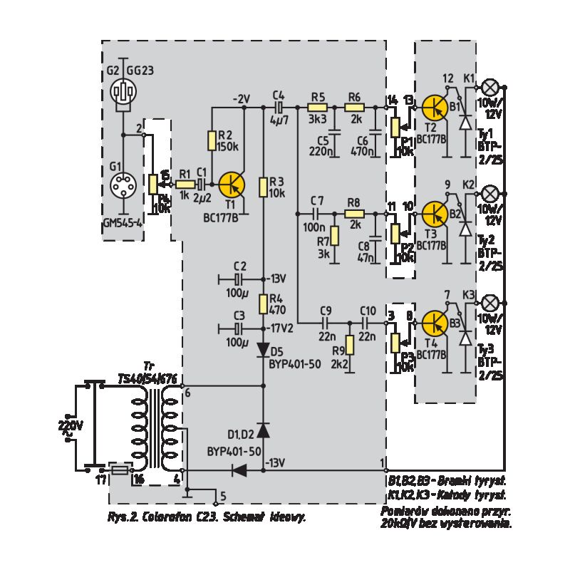
    40 years ago I got the schematic C23
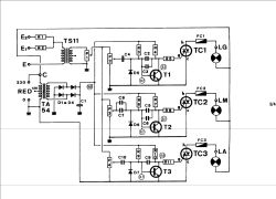
    Colorofon C23 electronic schematic with components like transistors and light bulbs. .
    I made my first working electronic circuit based on it. To increase the power, I gave more powerful bulbs 21W 12V . What was my surprise that the circuit didn't work very well because the delay on the bulbs was too high :( Only by changing the power supply to 24V did it work. I used the coloured glass used on the railway in semaphores as filters. I got them from a friend through acquaintanceship :) Back then everything had to be obtained ;) .
  • #29 21508683
    LEDówki
    Level 43  
    I had this diagram together with the colourophone, but put it somewhere. The colourophone is still in working order today. One knob is missing thanks to my brother-in-law.

Topic summary

The discussion centers on illuminophony, an 18th-century concept involving the modulation of colored light based on audio frequency bands, originally using incandescent bulbs with colored filters to produce RGB-like effects synchronized with music. Modern implementations use RGB LEDs controlled via PWM to achieve smoother, visually linear brightness changes corresponding to audio amplitude in low, mid, and high frequency bands. Challenges include achieving proper color mixing without discrete flashing, linear LED brightness control despite non-linear current-luminosity characteristics, and replicating the original smooth modulation rather than sharp flashing. Solutions involve using buffers (FIFO arrays) for smoothing audio samples, FFT for frequency analysis, and microcontroller-based PWM control. Hardware considerations include selecting appropriate development boards (ESP32 Dev Module preferred over ESP32 C3 for compatibility), managing ADC sampling rates (Arduino core version 1.0.4 recommended for >40kHz sampling), and using power LED drivers like the PT4115 for higher power applications. Historical references include vintage colourophone circuits (e.g., Colorofon C23B), use of painted incandescent bulbs, and triac-controlled 220V lamps with isolation transformers. The project is noted for low cost (~20 PLN) and minimal programming requirements, with emphasis on artistic impression over perfect white light mixing. The discussion also touches on the limitations of LED voltage control, the benefits of PWM, and the potential for digital signal processing to enhance effects beyond analog methods.
Summary generated by the language model.
ADVERTISEMENT