logo elektroda
logo elektroda
X
logo elektroda

Mitsubishi W142 AUX IN MP3 Homemade: Connecting RCA Input, CD Module, and Radio Compatibility

kutom 9586 4
ADVERTISEMENT
Treść została przetłumaczona polish » english Zobacz oryginalną wersję tematu
  • #1 8555577
    kutom
    Level 2  
    Hello, group members

    https://www.elektroda.pl/rtvforum/topic1634491.html#7933003&sid=#7933003

    On the forum you can find "RCA output" for the radio as in the subject, but I would like the opposite.
    The first question is: Will the radio play when there is no CD after pressing the CD button, when NO DISC is displayed?
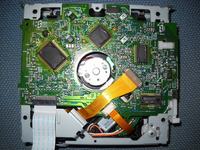
    2) If the above is happening, how do I plug in the module CD and the radio? There is one ribbon from the CD section to the rest of the radio, so I assume there must be three audio cables, like in headphones. Am I right?
    Mitsubishi W142 AUX IN MP3 Homemade: Connecting RCA Input, CD Module, and Radio Compatibility

    Thank you
  • ADVERTISEMENT
  • #2 9318235
    kutom
    Level 2  
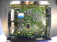
    I decided to try myself despite the lack of response. After undressing the radio, you can clearly see that the CD module is connected to one suspender with the rest. So I thought that one of these pins must be left, right channel and mass. Isolating pin by pin I found which one. As in the picture below, the shoulder straps (left, bottom corners) are marked with places where I soldered with the left and right channels, and mass. If I remember correctly, 1 pin is left, 2 is mass, 3 is right.
    Mp3 plays, unfortunately, a little bit softer than the radio and CD, and you need to have a blank track on the CD (repeat), because you will hear the CD track in the background.
    Works and probably with the advice of a specialist you could join in a better place and find a way that the CD does not have to play to unlock the input on the preamplifier

    Mitsubishi W142 AUX IN MP3 Homemade: Connecting RCA Input, CD Module, and Radio Compatibility
  • ADVERTISEMENT
  • ADVERTISEMENT
  • #4 12057446
    Zakatek
    Level 1  
    I have a big request. Could someone write what capacitors to use, i.e. the small one visible in the picture and the bigger one? to the original cables. I would like to try to do it though I can not decipher what is written there ;)
  • #5 21340140
    lorenzh920
    Level 1  
    I know this is super old, and I also do not speak Polish, but probing around I found that the pins on the image, from top to bottom seem to be arranged like this: R-ch, L-ch, and most likely ground (GND). The bottom most pin, GND, is connected to an Analog ground (AVss) on the MN662741RH Chip (pin 74). This is most likely speaker GND.
    From L-R, on the ribbon connector it is like this: pin 1: L, 2: R, 3: GND/AVss.
ADVERTISEMENT