logo elektroda
logo elektroda
X
logo elektroda

Where to install the pump on the supply or return in an open system?

maras0001 151790 46
ADVERTISEMENT
Treść została przetłumaczona polish » english Zobacz oryginalną wersję tematu
  • #1 10443977
    maras0001
    Level 10  
    Hello.
    I am asking specialists for advice on where to install the pump for central heating in an open system on the supply or return, because the stove will be in the kitchen and the pipes for the radiators would go horizontally under the ceiling and up under the radiators. Ceiling with a thickness of about 0.5m.
    Will the pump cope with the power supply?
    Should it be mounted on the return? :?:
  • ADVERTISEMENT
  • Helpful post
    #2 10444076
    kreslarz
    Level 35  
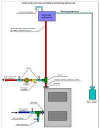
    I am a supporter of a feed pump due to some of the benefits that come with it. Diagram as in the picture below:
    Where to install the pump on the supply or return in an open system?
    When circulating pipes below the boiler, air vents must be installed in the right places, otherwise the system will be constantly aired and the pump will not be able to push the heating medium through.
    Sketch what it should look like in nature, it will be possible to suggest where to place the vents.
  • ADVERTISEMENT
  • #3 10444940
    Grzegorz Siemienowicz
    Level 36  
    There may only be a pipe between the boiler and the expansion vessel.
    There can be neither a valve nor a pump.
  • #4 10444997
    maras0001
    Level 10  
    https://obrazki.elektroda.pl/6750305700_1327451868.jpg

    The solution must be the same as in the diagram with the arrangement under the ceiling for radiators, there is no other option because in the apartment in each room there are two pairs of doors apart from the bathroom and there is no way to install the installation in the rooms and therefore I have some concerns whether the pump is on the power supply or on the returning known, the installation may contain air, please ask for professional advice :D
  • Helpful post
    #5 10445371
    kreslarz
    Level 35  
    Buddy, basic mistake: the expansion vessel must be connected directly to the boiler there cannot be any elements on the way, such as valves, pump, etc. - as I marked in my drawing. It's all about security. You have a vessel after the pump and you will have big problems if the water in the boiler is boiled! The rest of the installation is OK. It is necessary to install automatic air vents on the radiators, because due to the siphon system of pipes, they will get aired. Do not forget to supply the boiler to the boiler with cold water for filling and topping up the liquid in the system, and also install a valve for emptying the system from water if necessary at the lowest point.
  • Helpful post
    #6 10445568
    EkoGrzew
    Level 20  
    maras0001: For me, this gravitational pattern and diagram is almost meaningless to me. Why use it if it will not pass the exam anyway when there is no electricity. In fact, at this time the water heated in the boiler (solid fuel) will only supply the heater above the boiler and the overflow vessel well. If you really want to use a system with a solid fuel boiler and such a system, then the power supply should be led under the ceiling above the boiler and the supply risers should be brought down to the radiators below the boiler. You can run the return along the basement ceiling as shown in your diagram. Then you will always be sure that the heating water will be fully circulated and will even supply the radiators below the boiler when there is no electricity and it will not throw out the water through the overflow vessel. The point is that you should have one heating circuit - up and down, not as you have in the diagram now: up, down, up. As there are technical problems with such a distribution, you have to take into account what I wrote above. Besides, you don't use a differential valve, just a vertical check valve. And the pump in an open circuit on the supply. AND THE OVERFLOW TANK IS CONNECTED FROM THE RETURN WITHOUT ANY VALVES. THE MOST SEPARATE PIPE FROM THE RETURN PIPE AT THE BOILER.
    greetings
    (radoslav1)
  • Helpful post
    #8 10446417
    kreslarz
    Level 35  
    Picture 4527574800_1327494156 is correct.
    However, the picture 5057764900_1327494157 has a certain drawback. The circulation pump has a head of approx. 6 m. In the system shown in the figure, the water pumped towards the boiler outlet will take the path of the least resistance. This will cause an uncontrolled outflow of water from the expansion vessel. Such systems are often used, provided that the expansion vessel is at least 5 m above the boiler level. The system then works fine.
    EkoGrzew wrote:
    For me, this gravitational system and diagram is almost meaningless. Why use it if it will not pass the exam anyway when there is no electricity. In fact, at this time the water heated in the boiler (solid fuel) will only supply the heater above the boiler and the overflow vessel well.

    Not entirely without sense. Above the boiler there is an exchanger for DHW. In the event of a power failure, it is able to absorb the excess heat produced by the boiler. With an appropriate size, it is a buffer that prevents water from boiling in the boiler.
    EkoGrzew wrote:
    AND THE OVERFLOW TANK FROM THE RETURN WITHOUT ANY VALVES. BEST SEPARATE PIPE LOWERED FROM THE RETURN PIPE AT THE BOILER.

    Overflow vessel, maybe yes, but the expansion vessel protecting against steam explosion in the boiler definitely NOT. In the event of water boiling, the steam will collect in the upper part of the boiler and when the expansion vessel is mounted on the supply outlet pipe, it will find an immediate outlet to the atmosphere through the vessel and its opening to the atmosphere without causing any damage. When a vessel is installed on the return pipe, the steam must first force all the water out of the boiler to find an outlet to the atmosphere. In the meantime, he will probably find another way, destroying the boiler or one of the elements of the system.
  • #9 10446717
    EkoGrzew
    Level 20  
    Draftsman: Read the post carefully. The title itself says that it is an open system, and therefore with a non-expansion overflow vessel (nomenclature reserved correctly for diaphragm vessels) which is used in closed systems. Anyway, you have also included the diagram with the overflow vessel, by the way, let it be an open expansion vessel as already.
    Installations or a boiler are not destroyed by steam, but by pressure. The pressure is nothing more than the height of the water column: 1 atm = 10 m and it does not matter whether it will be in the tube fi 12 or fi 120. Each hydraulic device withstands at least 10 bar, so in other words, the height of 100m of water column! Do you see the installation of an overflow vessel at this height somewhere? Do not confuse the pressure with the weight of the water. By the way, we are here to help others and not to conduct discussions and prove who is right. I do not know electronics, so I do not speak, but I can say that I have removed many failures of the electronic system from the boilers without replacing the drivers, but I do not comment on electronics in the forum ... And you too, please ... take care of your profession. And help people where you are sure of your physics.
    greetings

    maras: I don't know what you're up to. the first pattern was the best and probably the simplest. pump on the supply. use these tips if possible, which I described above.

    PS
    to installers:
    The draftsman added an installation diagram: there is an overflow vessel on the suction side of the pump. Can someone authorize such a solution?
  • #10 10446759
    Grzegorz Siemienowicz
    Level 36  
    EcoHeater .....
    I also read the posts Draftsman -aiz his statements, I know that he understands installations (although sometimes I have a different opinion). That he understands means he won't botch something like some of the people calling themselves "service technician" or "installer".
    If you want, you can check out the whole thread of installers / service technicians on this forum.
  • #11 10446817
    EkoGrzew
    Level 20  
    Grzegorz S ....: I do not deny the skilled worker as a person, but I have doubts about his technical knowledge in the field of plumbing. I am waiting for the comments of people related to this subject.
    I also did not avoid errors and this portal is here to help. And in this particular case, according to my knowledge and practice, I can see that it can be harmful.
    greetings
    (radoslav1)
  • #12 10446904
    maras0001
    Level 10  
    Hello: EKO Grzew, you say that the best solution would be in the first scheme 4527574800-1327494156
  • Helpful post
    #13 10446911
    EkoGrzew
    Level 20  
    regarding the assembly of the vessel in the open configuration, please refer to:

    https://www.elektroda.pl/rtvforum/topic1900517.html

    Added after 2 [minutes]:

    no maras. your first schematic. only swap the vessel connection from supply to return. although this one could also be.

    https://obrazki.elektroda.pl/6750305700_1327451868.jpg

    Added after 1 [minutes]:

    or wait for others to comment on the topic. I'm waiting for the opinions of the service technician73 and mirrzo
  • #14 10448242
    maras0001
    Level 10  
    I will stick to the first diagram, only add an expansion pipe from the supply connector to the expansion vessel and leave the pump with the differential valve on the bypass or connect it directly to the radiator supply thread. :?:
  • Helpful post
    #15 10448972
    EkoGrzew
    Level 20  
    do you ask about air vents? if the installation is to look like in the diagram, it should be mounted on the power supply. personally, i only recommend afriso vents. and, in addition, on standard radiators.
  • #16 10449048
    maras0001
    Level 10  
    One more question is to use a bypass differential valve or not :D
  • ADVERTISEMENT
  • #17 10449126
    EkoGrzew
    Level 20  
    do you mean a gravity CO check valve (with a ball in the middle)? of course it must be. otherwise the pump may pump water into the boiler via the feed :) and consider that the pump is a bypass. You install the valve on the main supply riser. anyway, as you drew it on your diagram. (1)

    Added after 22 [minutes]:

    the best way to install the vessel would be according to this scheme:

    http://forum.info-ogrzał.pl/index.php?app=core&module=attach§ion=attach&attach_rel_module=post&attach_id=12316

    use for your installation
  • #18 10451750
    maras0001
    Level 10  
    Hello, I looked at this diagram and in the diagram we have two floors above the vessel we have an expansion pipe and a safety pipe will it pass the test because where the boiler is to stand, the height is 2.60 m from the floor to the ceiling with the connection as in the diagram that I got from you, the vessel must have to hang right above the boiler, it is not possible to hang it above, I am waiting for the answer: best regards :D
  • Helpful post
    #19 10456036
    EkoGrzew
    Level 20  
    hi
    read this post. Just don't make mistakes like there and follow the advice of the users and you'll be fine.
    and the diagram of what I sent you only as an illustrative one and it concerned only the vessel itself - its correct connection. if you give a pump on the supply, it is enough if from under the vessel it will be above about 0.5 m above the highest heating point. a little more from calculations, but from practice it is enough (see: https://www.elektroda.pl/rtvforum/topic1900517.html)

    https://www.elektroda.pl/rtvforum/topic2154683.html
  • #20 10456416
    maras0001
    Level 10  
    Thanks for the hint, this installation is really tragic. I watched the photos, it was tragic. Expansion vessel connect according to the instructions safety pipe from the top of the supply vessel between the boiler and the nearest valve and the expansion pipe from the bottom of the vessel on the return near the boiler ok greetings :D
  • ADVERTISEMENT
  • #21 10466989
    EkoGrzew
    Level 20  
    I did not understand with this valve. I repeat. any valves on the supply and return to the vessel, if there is any one, do a separate connection.
  • #22 10467357
    maras0001
    Level 10  
    Hello, with this valve, I meant that I would put a tee on the supply between the boiler and the differential valve and connect the safety pipe and the expansion pipe on the return to the cat there, and is it possible, for example, to connect the expansion pipe from the supply to the boiler outlet and connect it to the bottom of the vessel and the pipe safety from the expansion vessel to the top, best regards
  • #23 10472718
    EkoGrzew
    Level 20  
    Properly connected vessel is nothing more than, in a sense, a heater at the highest point - so it should be connected in the same way as a radiator. supply upstairs return downstairs. in addition, a vent (snorkel) and an overflow pipe.
  • #25 10472941
    saskia
    Level 39  
    Whether it is the lower or the upper supply, it does not make too much difference, it is important that the whole thing is professionally made, and especially that the appropriate cross-sections and slopes of the pipes are taken into account.

    As for the location of the pump, in my opinion, it is better to return to the boiler.
    With the maintained slopes and cross-sections, it increases the heat reception from the boiler, i.e. faster heating of the system.
    The laws of physics confirm that higher pressure in the boiler itself increases (strengthens) the contact of water with the boiler heating surfaces, and thus faster heat removal. At the same time, the pump creates a slight underpressure in the radiators, which causes a temperature drop, which means that heat is released faster.
  • #26 10513231
    msawik
    Level 9  
    Hello,

    Gentlemen, I do not want to start a new topic, so here I am asking for your opinion on the heating and hot water installation diagram as in the attachment. Is it ok. And please tell me if this location of the pump for what (on the boiler side) allows the installation of an overflow vessel in the boiler room - is it on the return and according to this principle, the overflow vessel should be 0.7xHp higher?
  • #27 12954520
    rokefeler
    Level 15  
    Hello and I am sorry that I am writing in the old topic, but I would like someone to explain to me the requirements of the requirement that in the case of the pump on the boiler return, the overflow tank should be 07xH of lifting the pump above the radiators. Such a case would be real for me if the pump was in the pond. After all, the pump is pushing water to the boiler, but it will be drawn from the radiators and the boiler when a vacuum is created, so the water will go there from where the pump sucked out. And it will certainly not go to the overflow because it has no return and the pump will not vacuum it. Thank you in advance for the explanation.
  • #29 12999801
    nautes
    Level 13  
    The pump head is not the head :) .
    Pressure is key here. the pump does not raise anything, it just has to force circulation. The task of the pump is to help overcome pressure losses in the system, NOT to RAISE.

    The zero point is the expansion vessel. In the pump, the pressure rises by the pressure of the pump. Later this difference is leveled on the web.

    With the pump in the flow, the highest radiator is at least under pressure higher than the pressure in the expansion vessel by the difference in height.
    So there will be no vacuum.

    In the case of the pump in the return, the most unfavorable pressure is even less the value corresponding to the "pump head".

    Edit: we could simply say that the pump pushes on the supply, and sucks on the return.

    Buddy marcinek96b.
    The scheme is incorrect.
    It is necessary to transfer the pump between the boiler and DHW return. Or the use of a check valve in the domestic hot water circuit (worse solution).

    Consider the advisability of using a differential valve and the possible addition of a pump to the domestic hot water.
  • #30 13930289
    tkotwa82
    Level 11  
    Hello
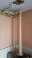
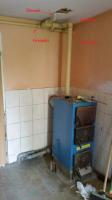
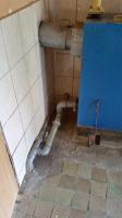
    I am trying to buy and install a pump. My question is where in my case is best to mount the pump. It is an old type of gravity heating. Due to the need to install additional heaters, there was a problem that the radiators at the very end of the circuit did not heat up very well. And there was a pump insertion solution. And as I wrote at the beginning, where to insert such a pump. If I can ask for advice, possibly send a solution (draw it in a photo or a drawing by hand :D . I attach photos of the currently connected system to the furnace.

Topic summary

The discussion revolves around the optimal placement of a pump in a central heating system using an open configuration. Participants debate whether the pump should be installed on the supply or return line, considering factors such as air venting, pressure dynamics, and system efficiency. Key points include the necessity of connecting the expansion vessel directly to the boiler, avoiding any valves or pumps in between for safety reasons. The consensus leans towards placing the pump on the return line to enhance heat transfer and reduce the risk of air entrapment. Diagrams are shared to illustrate proposed configurations, emphasizing the importance of proper installation to prevent issues like water boiling in the boiler. Various opinions on the use of differential valves and air vents are also discussed, with recommendations for specific brands and models of components.
Summary generated by the language model.
ADVERTISEMENT