logo elektroda
logo elektroda
X
logo elektroda

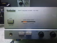
Technics SU-V460 - Does not turn on the relay, the transistors are heating up

cpikson 15618 14
ADVERTISEMENT
Treść została przetłumaczona polish » english Zobacz oryginalną wersję tematu
  • #1 11739320
    cpikson
    Level 15  
    Hello
    The problem is that after switching on the power supply on the front panel, only the "Voltage control" LED is lit and the other "Current drive" is not. In addition, the transistors on this small heat sink before the SVI terminal get very hot (checked with a meter they turned out to be operational), and of course the relay does not react. The tip itself does not heat up at all. Does anyone have any suggestions on what elements to check next, or maybe it's the fault of a burnt tip?
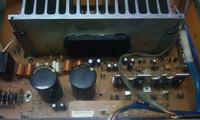
    Technics SU-V460 - Does not turn on the relay, the transistors are heating up Technics SU-V460 - Does not turn on the relay, the transistors are heating up
  • ADVERTISEMENT
  • #2 11740143
    mateos21
    Level 13  
    Check that there is no DC voltage at the loudspeaker outputs.
  • #3 11741729
    ugur
    Level 15  
    Disconnect the power supply from the Hybrid SVI3204 and check the voltages on these heating transistors (voltage amplifier).
  • #4 11743109
    cpikson
    Level 15  
    The voltages on pins 3 and 6, i.e. on the speaker outputs, are 0 V and 49 V, respectively, so there will be nothing from this terminal. On the other pins of the SVI3205, the voltages also in most cases do not coincide with the data sheet. Hence my next question, does anyone know where to get such a chip and at what price or how to replace it?
  • ADVERTISEMENT
  • #5 11747640
    mateos21
    Level 13  
    The originals are very expensive and the replacement is different.
  • #6 11747665
    cpikson
    Level 15  
    It would be a shame to turn such nice equipment into razor blades. Maybe someone has a suggestion what can be adapted as a power amplifier instead of the SVI? Of course, at a reasonable price and parameters at least a little close to the original.
  • #7 11747675
    ugur
    Level 15  
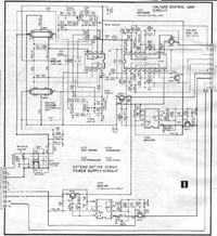
    DC voltage on the SVI3205 hybrid does not indicate a damaged power amplifier. Please check the voltages with the diagram on the AN7062 IC (located on the potentiometer board). This damaged IC often gives constant voltage to the hybrid.
  • ADVERTISEMENT
  • #8 11748954
    cpikson
    Level 15  
    I just checked the voltages on this AN7062 IC and almost all of them agree except for pins 16 and 17, where it should be 0 V and there are 12.8 V and 4.2 V respectively. There is a positive supply voltage on the unconnected pins.
    Technics SU-V460 - Does not turn on the relay, the transistors are heating up
  • #9 11749127
    mateos21
    Level 13  
    Do you know the best way to check this system with a meter? There is a simple way to do this.
  • ADVERTISEMENT
  • #10 11750061
    sebek20
    Level 11  
    I once dealt with a similar model (there, after a few seconds, these small transistors burned and the power had to be quickly disconnected.
    The reason was a damaged hybrid, which gave the maximum voltage value on one channel.

    Check if you don't have a significant DC voltage at the outputs of the hybrid. I don't know about your application, but in the amp I made, the correct value was +/- 60 mV at rest.
  • #11 11750102
    cpikson
    Level 15  
    mateos21 wrote:
    Do you know the best way to check this system with a meter? There is a simple way to do this.

    If you would be so kind, please share this valuable knowledge :D

    sebek20 wrote:
    I once dealt with a similar model (there, after a few seconds, these small transistors burned and the power had to be quickly disconnected.
    The reason was a damaged hybrid, which gave the maximum voltage value on one channel.

    Check if you don't have a significant DC voltage at the outputs of the hybrid. I don't know about your application, but in the amp I made, the correct value was +/- 60 mV at rest.

    I checked the output voltages and there is 0 V on one channel and +49 V on the other.
  • #12 11750689
    mateos21
    Level 13  
    Set the meter to the diode testing range, put the positive probe of the meter to the ground of the integrated circuit and the negative one to the other terminals of this system and the meter will show you the indications as if you were checking a diode. It's best when you desolder the system. Show me these instructions.
  • #13 11750896
    sebek20
    Level 11  
    cpikson wrote:
    I checked the output voltages and there is 0 V on one channel and +49 V on the other.

    So it looks like you have a busted channel in the hybrid.

    mateos21 wrote:
    Set the meter to the diode testing range, put the positive probe of the meter to the ground of the integrated circuit and the negative one to the other terminals of this system and the meter will show you the indications as if you were checking a diode. It's best when you desolder the system. Show me these instructions.

    This method is not always possible to check the hybrid.
    I had a case where the wire leading to the connector structure burned on one transistor in the hybrid, and the other one was functional, except that during the amplifier's operation the system drove it to full, which indicated a fault.
    However, after removing the power supply, the meter on the diode did not indicate anything because the transistor was operational, while on this burnt transistor it did not indicate anything either, because the wire leading to the emitter was burnt. After the autopsy of the hybrid was done, everything was visible.

    The fact is that the +49 V voltage appears on one channel, which indicates a hybrid failure (in principle, the external auxiliary elements surrounding such a hybrid do not break down, everything that can burn up along with the zero resistors is in this black cube).
    Just for peace of mind, disconnect the amplifier from the power supply, make sure that all capacitors are 100% discharged near the hybrid, especially the main ones in the filtration behind the bridge, then set the meter on the diode and apply it to the + power supply and the hybrid output of the channel on which +49 V appears. If there is a short circuit, you have a 200% hybrid.
  • #14 11751349
    mateos21
    Level 13  
    With this method, I wanted to check the AN7062 IC, although I assume it is operational and I bet on a damaged power amplifier.
  • #15 11847865
    cpikson
    Level 15  
    After all possible measurements, etc., there is only one conclusion, a stoned hybrid. With this, unfortunately, I consider the topic closed. Thanks for all your help and advice.

Topic summary

The Technics SU-V460 amplifier is experiencing issues where it does not activate the relay, and the transistors are overheating. The "Voltage control" LED is lit, while the "Current drive" LED is not. Users suggest checking for DC voltage at the speaker outputs and measuring voltages on the SVI3204 hybrid. The author reports abnormal voltages on the SVI3205 and AN7062 IC, indicating potential hybrid failure. Suggestions include checking for DC voltage at the outputs and considering the replacement of the hybrid with a compatible power amplifier. Ultimately, the author concludes that the hybrid is defective.
Summary generated by the language model.
ADVERTISEMENT