logo elektroda
logo elektroda
X
logo elektroda

Pioneer Amplifiers: PA0016 Chip Replacement, Circuit Diagram & Trusted Sources

majsterek 17073 25
ADVERTISEMENT
Treść została przetłumaczona polish » english Zobacz oryginalną wersję tematu
  • #1 17304545
    majsterek
    Level 25  
    Hello,
    Since I have already bought two PA0016 chips and both are unfortunately not working (I check them on a working channel), I wonder if they can be replaced. I found on the net this:
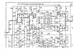
    Pioneer Amplifiers: PA0016 Chip Replacement, Circuit Diagram & Trusted Sources Pioneer Amplifiers: PA0016 Chip Replacement, Circuit Diagram & Trusted Sources
    Question
    - is it a real or a simplified diagram of this system?
    - in short, is it possible to make this simple layout and replace the original?
    - if not, where to buy a proven and working PA0016 today?
    Maybe someone has already worked on this topic and can confirm / deny it?
    Thank you in advance for your help
  • ADVERTISEMENT
  • #2 17304586
    jakubek56
    Level 32  
    There is a quiescent current regulator in this system.

    Added after 2 [minutes]:

    Wojtek(KeFir) wrote:
    It is responsible only for the stabilization of the quiescent current and the overcurrent protection of the power stage. Theoretically, you can run the amplifier without it at all.

    Without stabilization of the quiescent current, the amplifier may be damaged.

    Try to make this layout according to the diagram you sent.
  • #3 17304869
    aaanteka
    Level 42  
    Unfortunately, the PA0016 replacement solution is not that simple. After all, on the page from which you took the solution, you have the answer:
    Quote:
    Errors enthusiasm, short circuit protection transistors Q2, Q3 in the collectors have 1500 Ohm resistors! and are connected to the resistors in the Q129 and Q131 drivers base.

    Therefore, Q2 and Q3 cannot be protected and installed in vain.

    From UH in parallel to the resistor R4 = 100 ohms (in the enthusiasts diagram)

    in the amplifier circuit there is a circuit R159 = 270 Ohm + C119 = 68p, then through R171 = 100 Ohm to the base of the control transistor.

    NOT logical.

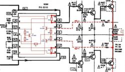
    In the Pioneer AX530 circuit, you can see the block diagram of the PA0016

    Pioneer Amplifiers: PA0016 Chip Replacement, Circuit Diagram & Trusted Sources

    Basically, the damage to PA0016 is a consequence of a malfunction of the rest of the system, in particular the input stage. There must be fairly precise symmetry in the circumference.
    What exactly is the amplifier model do you have?
  • #4 17305784
    zadam64
    Level 39  
    Hello, and also in the VSX 512K receiver
  • ADVERTISEMENT
  • #5 17305909
    wkj
    Level 37  
    If you buy some "coloring books" then the new ones do not work. In fact, I did not pursue the topic of where and if the original can be purchased.
    If the amplifier is of a higher model, you can always use parts from weaker, lower models with the same quiescent current stabilization solutions of the power stages.
  • #6 17307841
    PZ IX
    Level 35  
    Hello

    And where did your colleague buy these systems from? Is it Cybor Tech? Do they confirm that they are original systems? Because if you took a new one for PLN 20-30, then you are worried about originality ...

    I bought these systems 7 years ago for PLN 50-70. From what I can see, North has them, but the price is prohibitive (PLN 104), unless you find good spines, sometimes it works.

    I hope that the rest of the system is 100% efficient and helpful 230V bulb is plugged in in series?
  • ADVERTISEMENT
  • #7 17307922
    majsterek
    Level 25  
    aaanteka wrote:
    What exactly is the amplifier model do you have?

    Pioneer A656
    wkj wrote:
    If you buy some "coloring books" then the new ones do not work.

    I asked the Sellers. They said they were the originals. I paid about PLN 70 with the shipment
    PZ IX wrote:
    Hope the rest of the system is 100% working

    So efficient, I wrote that I check the systems in a working channel
    PZ IX wrote:
    a helpful 230V bulb is plugged in in series

    I did not plug in the bulb. I check with a desoldered power amplifier
    PZ IX wrote:
    unless you find good hatches

    I am happy to buy such a system
  • #8 17308189
    PZ IX
    Level 35  
    majsterek wrote:
    operational, I wrote that I check the systems in a working channel

    OK, I didn't read it.
    majsterek wrote:
    I check with a desoldered power amplifier

    Well, in fact, the bulb could not be useful for a lot. My 60 watt control stage was burning in the Tosca 303 as I had an error in the system.

    Does the working PA work for you also with soldered transitions? final?

    What am I going to? Well, PA0016 can be equipped with quiescent current detection, which interrupts the operation of the system in the event of extremely incorrect values. Not having plugged transducers. end, you are definitely reducing this current.
  • #9 17308241
    majsterek
    Level 25  
    PZ IX wrote:
    Does the working PA work for you also with soldered transitions? final

    Yes, although it has twice the voltage at output 9 and 13. But it maintains symmetry. I must admit that this method has already been described by my colleagues on the Electrode. In this way, they verified the correctness of PA0016 operation.
    I would like to try with a connected power amplifier, but I am afraid of the consequences if it turns out to be wrong. Are you saying that securing with a light bulb will not work?
  • #10 17308663
    PZ IX
    Level 35  
    The bulb may fail and at worst will only save at best the end transistors.

    Anyway, since an efficient PA maintains the symmetry, and after the swap everything starts to bloom, the problem is clearly in the purchased systems.

    There is one Buy It Now auction with these layouts on Allegro. Please take a look and tell me if yours look the same, because I don't remember seeing a Pioneer badge in the form of PacMan on this layout. If this is the case, I would still demand that the systems be returned to the seller.
  • #11 17310056
    aaanteka
    Level 42  
    PZ IX wrote:
    What am I going to? Well, PA0016 can be equipped with quiescent current detection, which interrupts the operation of the system in the event of extremely incorrect values. Not having plugged transducers. end, you are definitely reducing this current.

    There is no such thing in the system, therefore, at the slightest malfunction, the system is damaged.
    There is, however, the "Over load detector" detection system and the measurement of voltage drop across pin 10 and pin 12 emitter resistors. Lack of proper continuity in this path may cause various malfunctions.

    Replacing a working system that is working properly with a system purchased for checking seems quite unreliable in such a precisely working system. The monolithic structure is not identical and similar, therefore each copy will have slightly different operating parameters - the spread.
    It is good to physically and actually check all the values of the cooperating elements, as well as the continuity of connections.
    After all, there are not that many of them.
    majsterek wrote:
    Are you saying that securing with a light bulb will not work?

    No, not in this amplifier, as in many others, it will not work. Please check the amount of charge in the filter capacitors. Calmly enough energy is enough to damage several such end stages. The optimal protection that always works is to limit the current between the stage itself and the amplifier's power supply. This is not always easy to do, but it is and can be done in several ways.
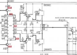
    Pioneer Amplifiers: PA0016 Chip Replacement, Circuit Diagram & Trusted Sources
    In this particular model, we have a simplified checking thanks to the possibility of checking the circuit itself (symmetry on pin 8-14) and the circuit with only Q129 / Q131 first stage transistors mounted, and then Q133 / Q135 next stage transistors mounted. At each stage, we check the symmetrical operation of the system manifested by 0 voltage on pin 11.
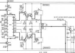
    Pioneer Amplifiers: PA0016 Chip Replacement, Circuit Diagram & Trusted Sources

    The assembly and checking of the Q1 and Q3 final stage elements is a pure formality in the case of correct symmetrical operation in the earlier stages of commissioning.
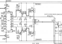
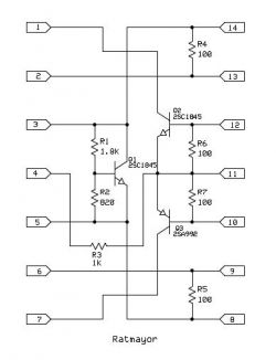
    Pioneer Amplifiers: PA0016 Chip Replacement, Circuit Diagram & Trusted Sources
  • #12 17311324
    wkj
    Level 37  
    aaanteka wrote:

    majsterek wrote:
    Are you saying that securing with a light bulb will not work?

    No, not in this amplifier, as in many others, it will not work. Please check the amount of charge in the filter capacitors. Calmly enough energy is enough to damage several such end stages. The optimal protection that always works is to limit the current between the stage itself and the amplifier's power supply. This is not always easy to do, but it is and can be done in several ways.

    Sometimes I put resistors between the power supply and power amplifiers, 20? 20W, limiting the current, always faster than the idea with a light bulb.

    From a different barrel: maybe an extreme idea, but - if the author does not buy the circuit or has a "coloring", then maybe it is worth thinking about converting it into a discrete quiescent current control circuit taken from sevens amplifiers? 676 and 777 have them. Unfortunately, both channels would have to be redone.
  • #13 17311379
    majsterek
    Level 25  
    Sorry for the break in writing but unfortunately there is not always time. So in short answer:
    PZ IX wrote:
    because I don't remember seeing a Pioneer badge in the form of PacMan on this layout

    There is a stamp, the layouts look very similar
    aaanteka wrote:
    The monolithic structure is not identical and similar, therefore each copy will have slightly different operating parameters - the spread

    Please tell me what you have written. Because I was also thinking about it, if it is not necessary to change their working points. But where and how?
    aaanteka wrote:
    It is good to physically and actually check all the values of the cooperating elements, as well as the continuity of connections.
    After all, there are not that many of them

    System environment checked. Besides, it's a working channel. Besides, I currently have both channels working, but unfortunately only one working PA0016 :-) .
    aaanteka wrote:
    In this particular model, we have a simplified checking thanks to the possibility of checking the circuit itself (symmetry on pin 8-14) and the circuit with only Q129 / Q131 first stage transistors mounted, and then Q133 / Q135 next stage transistors mounted. At each stage, we check the symmetrical operation of the system manifested by 0 voltage on pin 11.

    This is how I check these layouts. No end step connected. The new circuits no longer have symmetry on the power supply itself. The negative voltage is on the order of about 1V and the positive voltage is practically equal to zero.
    wkj wrote:
    maybe it is worth thinking about converting to a discrete quiescent current control circuit taken from amplifiers of sevens?

    An interesting idea worth developing.
  • #14 17311782
    aaanteka
    Level 42  
    majsterek wrote:
    This is how I check these layouts. No end step connected. The new circuits no longer have symmetry on the power supply itself. The negative voltage is on the order of about 1V and the positive voltage is practically equal to zero.


    But where exactly these tensions occur and at what stage of checking. Because we can only guess our colleague's actions.

    wkj wrote:
    maybe it is worth thinking about converting to a discrete quiescent current control circuit taken from amplifiers of sevens? 676 and 777 have them. Unfortunately, both channels would have to be redone.

    majsterek wrote:
    An interesting idea worth developing.

    Hmm, that's where my friend started the topic? The main argument against this solution is the change of the "superA" class to the regular AB class. In a word, say goodbye to the sound of the A656 with a considerable amount of work. In addition, there is always a risk of a mediocre final effect.

    Advertise the purchased system as soon as possible, unless it was first inserted into the damaged channel and then checked in the latter.
  • #15 17311794
    majsterek
    Level 25  
    aaanteka wrote:
    at which stage of checking

    I carry out measurements with mounted Q129 / Q131 first stage transistors and Q133 / Q135 second stage transistors. The power transistors are unsoldered.
    aaanteka wrote:
    where exactly these tensions occur

    Feet 14 and 8 of the PA0016 system. This translates into incorrect tensions on legs 13 and 9 (lack of symmetry and too low tensions). I will add what I already wrote that installing the only efficient and original circuit that I have in the same channel causes its correct operation (voltages in accordance with the diagram, symmetry of voltages on legs 13 and 9) and the entire power amplifier.
    In my opinion, I either have "painted" systems, or they differ in parameters so much that they have to be controlled differently to work properly.
  • ADVERTISEMENT
  • #16 17312182
    aaanteka
    Level 42  
    If you want to experiment with these purchased systems, I suggest that, if you can do it reliably and correctly, measure the current flowing to pin 14 and pin 8 (at the mA level). If these currents do not flow, the system is damaged.
  • #17 17312446
    majsterek
    Level 25  
    aaanteka wrote:
    if you can do it reliably and correctly, measure the current flowing to pin 14 and pin 8 (at mA level)

    I will try to take such a measurement and provide the results.
  • #18 17312511
    PZ IX
    Level 35  
    majsterek wrote:
    I have "painted" circuits, or they differ in parameters enough that they have to be actuated differently to work properly.


    In my opinion, only the former. I have not heard of this type of problem with PA0016 chips. Assembled with functional peripherals it must work.
  • #19 17312715
    aaanteka
    Level 42  
    Oh, PA0016 can be very capricious and demanding, among others in this model and A91D. It is also a fact that the current licensed products work in some models and do not want to in others (especially in the oldest solutions).
    But there was a problem with this Pioneer patent solution from the start, even during the warranty period.
  • #20 17314452
    PZ IX
    Level 35  
    At home in the VSA-1000 I did not notice any problems. He started off the kick. :)

    It is a pity that these arrangement solutions used to be so capricious. After all, old audio equipment should be characterized by construction reliability both in the time of their production and with the passage of years, at most age-appropriate repairs and should continue for years.

    To be honest, on the Electrode I read a few posts that in difficult working conditions (parties) PA0016 sometimes refused to obey and it would not be surprising if it were not for the high prices of these systems in relation to their capabilities. After all, for PLN 100, you can buy a set of transistors for some older Yamaha or even Pioneer without this type of fancy at good prices.

    Since it can be such a troublesome circuit, on my part I suggest - if it is your equipment - after a successful repair, sell the amplifier for a reasonable price and buy something older and more successful. I did it myself when I thought it was time to sell something with an STK or other unusual circuit and buy equipment that is simpler and easier to repair - this applies mainly to amplifiers.
  • #21 17323475
    aaanteka
    Level 42  
    PZ IX wrote:
    To be honest, on the Electrode I read a few posts that in difficult working conditions (parties) PA0016 sometimes refused to obey and it would not be surprising if it were not for the high prices of these systems in relation to their capabilities. After all, for PLN 100, you can buy a set of transistors for some older Yamaha or even Pioneer without this type of fancy at good prices.

    Because this is not a dedicated amplifier with parameters that actually exceed typical class AB transistor designs. Well, "audiophiles" appreciate its sound until the present day.


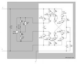
    Pioneer Amplifiers: PA0016 Chip Replacement, Circuit Diagram & Trusted Sources

    The above discreet design of the system has been implemented in several designs that are favorably reviewed. It is a bit better solution than PA0016, because it has full quiescent current control.
  • #22 17329087
    PZ IX
    Level 35  
    aaanteka wrote:
    o an amplifier with parameters that actually exceed the typical class AB transistor designs is not intended for this purpose. Well, "audiophiles" praise its sound until the present day.


    Yes, but I prefer and recommend solutions without any freaks. Old Yamaha or Harman Kardon also get very good opinions, and they were often implemented only with the use of typical elements.
    It is true that it is a pity to combine such an amplifier with substitutes, but in Harman, for example, I was very pleasantly surprised by the fuse resistors, which protected the entire system. And on my current Kenwood KA-7X, repairing the steering stage did not cost a fortune. Although if it failed very much and burned all the final Toshibas, it would not be cheap on the full originals (I'm deliberately omitting a bit of other Sanken here - privately I would go for a full factory here), but I prefer it to Pioneer - in the VSA-1000 I had the final burned and I had to do a bit other insert + to this today already high cost of PA0016.

    An amplifier is an amplifier, one of the most vulnerable devices in the audio path, and it should be a design that is easy to repair.
  • #23 17329228
    aaanteka
    Level 42  
    Therefore, a discrete solution as shown can be used higher and enjoy the full Super A class for little money compared to PA0016 and similar systems.

    PZ IX wrote:
    An amplifier is an amplifier, one of the most vulnerable devices in the audio path, and it should be a design that is easy to repair.

    But it is not ? The cost of repair is different.
  • #24 17329419
    PZ IX
    Level 35  
    aaanteka wrote:
    Therefore, you can use a discrete solution as presented above and enjoy the full Super A class for little money compared to PA0016 and similar systems.

    It is possible that the sound will be good, but it is still an interference in the factory and for me a much smaller modification is the insertion of typical electronic transistors instead of the originals in some Japanese, fully discrete construction. Which does not mean that I am a supporter of both.

    aaanteka wrote:
    PZ IX wrote:
    An amplifier is an amplifier, one of the most vulnerable devices in the audio path, and it should be a design that is easy to repair.

    But it is not ? The cost of repair is different.

    In my opinion, it is not, because you have to buy the expensive PA0016 or modify the system. Following this path, the Technics SU-v560 is affordable, because in the event of burning the whole AA class chain, I will put something else. Well, what will be left of the original? Sure, you can have such an approach, but most of all, it's not the equipment anymore.

    And the costs are always there, as long as we want to use exactly the same transistor models as the manufacturer. A good replacement is also not bad - I am able to understand it despite my opinion on this subject.
  • #25 17329489
    aaanteka
    Level 42  
    Buddy, the original does not suit you, because it is too expensive. The alternative is not a factory. You have to make up your mind and choose the right option. By the way, my colleague understands the functioning of the super A class (in fact, it's just a trade name for a pretty cool solution)? In the years of popularity, they were made at the factory either using dedicated systems to reduce production and commissioning costs, or, as JVC, was done discreetly.

    The topic of this thread should also be remembered.

    The aforementioned SVI 3205 for Technics is available in a new version, but it is difficult to expect the same production after such a time. On the other hand, with such old equipment, it is difficult to require repair for a symbolic zloty. After all, this is only a bit of equipment for a connoisseur or audiophile with sentiment.
  • #26 17330259
    PZ IX
    Level 35  
    aaanteka wrote:

    Buddy, the original does not suit you, because it is too expensive

    It's expensive, but that's another matter altogether. I like my Kewnood kit (KA-7X and KT-9X) and there are no replacements or modifications, so the price doesn't matter. Anyway, I wrote this:
    PZ IX wrote:
    And on my current Kenwood KA-7X, repairing the steering stage did not cost a fortune. Although if it failed very much and burned all the final Toshibas, it would not be cheap on the full originals (I'm deliberately omitting a bit of other Sanken here - privately I would go for a full factory here), but I prefer it to Pioneer - in the VSA-1000 I had the final burned and I had to do a bit other insert + to this today already high cost of PA0016.

    In my opinion, the amplifier, and especially the final stage built on unusual elements, is an excess of form over content and only the manufacturer will benefit from it - lower costs in the production phase, because silicon wafers are a much cheaper matter than installing THT in each unit and forcing the purchase of new equipment for most consumers (those who do not want to repair for various reasons). And the integrated circuit itself ceases to produce, stocks disappear and there is a problem, as happened with STK a few years ago.

Topic summary

The discussion revolves around the replacement of PA0016 chips in Pioneer amplifiers, particularly in the context of the A656 model. Users express concerns about the reliability of replacement chips, with some suggesting that the failure of the PA0016 may stem from issues in the amplifier's input stage rather than the chips themselves. Circuit diagrams are debated, with emphasis on the importance of quiescent current stabilization to prevent damage. Users share experiences regarding sourcing original PA0016 chips, noting that many replacements may not be genuine. Suggestions include measuring currents at specific pins to diagnose issues and considering alternative discrete designs for improved reliability. The conversation highlights the challenges of maintaining older audio equipment and the potential for modifications to enhance performance.
Summary generated by the language model.
ADVERTISEMENT