logo elektroda
logo elektroda
X
logo elektroda

Wiring Diagram for 13-Pin Trailer Socket Connection (Germany)

Miś21 186088 44
ADVERTISEMENT
Treść została przetłumaczona polish » english Zobacz oryginalną wersję tematu
  • #31 11754861
    viper555
    Level 39  
    It turns off the fog in the car and turns on in the trailer.P
  • ADVERTISEMENT
  • #33 11755025
    hubertbaran
    Level 17  
    If I may interject, I do not recommend mounting sockets "live" to the bundle, even in older constructions. A module that is not expensive works much better. Most have diagnostics that make life easier in the event of a damaged stop lamp or direction indicator. It does not burden the installation that is in a different condition. Also eliminates the problem of micro contact in the socket (not necessary)

    As for the type of socket, the 13-pin socket is super useful in my opinion, sometimes the "outside" power supply is useful. Much better to fasten it and hold it securely.
  • #34 16305408
    Junior_86
    Level 10  
    goliat777 wrote:
    viper555 wrote:
    Wiring Diagram for 13-Pin Trailer Socket Connection (Germany)

    Why correct the original.P


    what is this gray contactor with two gray cables for. when i put the plug in what does it turn on.???


    you can see here, as in my socket, that one wire is bridged. Plus to the anti-fog, and the other one?? where to put it?? goes out to the trunk with a wiring harness. If it's ground, why isn't it bridged? Or does it only work with an add-on? I cut out the module because I bought it used and it was hard to get to the load - half of the wires were cut during disassembly. I put in a "short"
  • ADVERTISEMENT
  • #35 16305543
    borbet
    Level 13  
    Junior_86 wrote:
    goliat777 wrote:
    viper555 wrote:
    Wiring Diagram for 13-Pin Trailer Socket Connection (Germany)

    Why correct the original.P


    what is this gray contactor with two gray cables for. when i put the plug in what does it turn on.???


    you can see here, as in my socket, that one wire is bridged. Plus to the anti-fog, and the other one?? where to put it?? goes out to the trunk with a wiring harness. If it's ground, why isn't it bridged? Or does it only work with an add-on? I cut out the module because I bought it used and it was hard to get to the load - half of the wires were cut during disassembly. I put in a "short"


    Which "bridge" are you talking about? Gray or brown? Gray is unfastening the PM of the car after connecting the trailer plug. Brown is double mass.
  • #36 16305682
    Junior_86
    Level 10  
    o gray with white stripe.
  • #37 16306220
    borbet
    Level 13  
    Junior_86 wrote:
    o gray with white stripe.


    As I wrote PM. Gray with a stripe is the rear PM power supply in the car, which is disconnected after connecting the trailer.

    Example below:
    Wiring Diagram for 13-Pin Trailer Socket Connection (Germany)
  • ADVERTISEMENT
  • #38 16312815
    Junior_86
    Level 10  
    please explain it to me in layman's terms. what should I connect this "gray with a white stripe" the other one I understand is a bridged PLUS PM light.
    I have such a fairy tale in the 7PIN socket. but so far "gray with a white stripe" not connected.
  • ADVERTISEMENT
  • #39 16312998
    borbet
    Level 13  
    Junior_86 wrote:
    please explain it to me in layman's terms. what should I connect this "gray with a white stripe" the other one I understand is a bridged PLUS PM light.
    I have such a fairy tale in the 7PIN socket. but so far "gray with a white stripe" not connected.


    Connect as shown in the picture (2 - fog light feed and 14 - fog lamp return). You just need to cut into the power circuit. This applies to the circuit in the car. However, I advise against such treatments in a car with bulb control or CAN bus.
    This type of socket is also available in the 7-pin version. I mean the switch that disconnects the power supply to the rear PM lamp of the car.
  • #40 16314472
    Junior_86
    Level 10  
    I don't understand ;) is gray with a b. stripe a mass? or what? I rather have a can bus but does it bother me?? passat b5 2000
  • #41 16314804
    borbet
    Level 13  
    Junior_86 wrote:
    I don't understand ;) is gray with a b. stripe a mass? or what? I rather have a can bus but does it bother me?? passat b5 2000


    1. The switch in the socket (7 or 12 pin) is to turn off the rear PM in the car when the trailer is connected.
    2. To turn off the PM in the car, you need to plug into the car's installation (2 - fog light feed - PM supply in the car and 14 - fog lamp return - PM supply return - from the trailer socket) - then the PM shines either in the car or in the trailer
    3. In cars after +-96-99r. (I assumed this as the end of golf mkIII production), and certainly, if the manufacturer requires it, it is best to use the trailer module, because it does not burden the car's electrical system
    4. The module can be universal (e.g. with Allegro) or dedicated to the car (a more expensive solution, because in addition to the price of the module, you may need to upload the software to the car, but usually there is no need to cut, solder, etc.). With a dedicated one, it is best to also have the original harness and hook socket.
    5. Universal modules have instructions and connection diagrams, but it is also good to have a car wiring diagram, multimeter and a bit of knowledge. It is often better to spend PLN 100-200 for connecting the module / socket of the towbar than to do something yourself and burn the car's electronics (CAN, control modules, etc.), because here repair prices start from a bag of coins.

    PS On the VAG group after 96. I don't know much, but for example, in such a Volvo V70 until 2004, you can connect the towbar installation to the installation of the car without the module (it is optional) and from 2005. there must already be a module (because, for example, after connecting a trailer, it changes the characteristics of the automatic transmission).
    Added after 9 [minutes]:
    Junior_86 wrote:
    passat b5 2000


    hmm. I used the "Search" option...

    https://www.elektroda.pl/rtvforum/topic1183208.html

    This reminded me that in the Golf III I had a separate free connector in the (probably) left lamp with pins for the trailer socket. I simply connected the socket of the hook with pins clamped on the wires.
  • #42 16316624
    Junior_86
    Level 10  
    It reminds you well of those extra contacts in the lamps. I know all this. I just didn't know how to make it good :) all in all, it still means little to me when the PM returns from the socket. It seems to me that the left rear lamp PM is One wire, the so-called "Plus" and the general mass - as the second wire closing the circuit ;)
  • #43 16316686
    borbet
    Level 13  
    Junior_86 wrote:
    It reminds you well of those extra contacts in the lamps. I know all this. I just didn't know how to make it good :) all in all, it still means little to me when the PM returns from the socket. It seems to me that the left rear lamp PM is One wire, the so-called "Plus" and the general mass - as the second wire closing the circuit ;)

    You are cutting into the (+) PM supply circuit. The power goes to the trailer socket. Return connects to this switch.
    In the situation without a trailer - the power supply goes through the socket and further to the PM of the car.
    When the trailer plug is connected, the switch disconnects the return to the car's PM and only the trailer's PM is lit,
  • #44 19729104
    ericssoun3m
    Level 9  
    Hello users,

    I have a request for help because I am unable to connect the plug to the 13-pin socket from the Brenderup trailer.
    All the schematics I found have the following description of the plugs/cable colors:

    1. Left indicator (yellow)
    2. Fog lamp (blue)
    3. Ground (white), pins 1-8
    4. Right indicator (green)
    5. Right position lights (brown)
    6. Brake Lights (Red)
    7. Left position lights (black)
    8. Reverse Lights (Red/Black)
    9. Constant Voltage (Orange)
    10. Charging terminal (purple)
    11. Empty
    12. Empty
    13. Ground (brown) pins 9-13

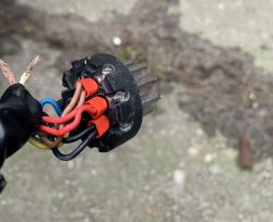
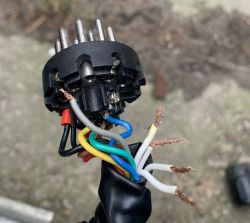
    Meanwhile, my beam - as you can see in the pictures has:

    - bridged (factory) cables 2x brown, 2x black, 2x red
    - there are 4 white (mass) wires, there are no "free" brown - mass wires
    - there is no single orange wire (there is one free one, gray)
    - there is no purple wire

    I connected brown, red and black stranded wires to pins 5-6-7 respectively, single yellow, blue and green wires to pins 1-2-4 respectively.
    I have no idea if these 4 loose wires are all ground - but assuming that I bridged them (twice under two white wires) and connected them to ground plugs, i.e. 3 and 13. Nothing works in this system (positions, direction, feet, number plate lights) except for the two side marker lights. The side marker lamps also do not work when the jumpered grounds are disconnected from pins 3 and 13.
    I also do not understand what the pin descriptions are on the occasion of the position of the mass wires (i.e. there was a mass of plug 3, pins 1-8 and a brown mass (which I do not have) plug 13 and pins 9-13).

    I have absolutely no idea what is going on here or how to deal with it / determine which wire is responsible for what.
    I kindly ask people with better electrical knowledge (and/or the ability to understand diagrams, because I have little to do with it) for any help and an indication of how to determine exactly what my 4 white "mass" wires are and how/to which plugs I have connect them, why the factory bridged the wires 2x brown, 2x red, 2x black (since the diagram indicates otherwise) and what is this one "free" gray wire, because I simply have no idea how it should be for it to work - because even these wires that have the correct colors and are in "their" pin numbers (i.e. yellow, blue, green) also do not turn on the lighting that they should - specifically, nothing turns on (except for the outlines mentioned after connecting the bridged, white wires to the pins 3 and 13).

    I appreciate any advice, thank you in advance!
    e.
    Wiring Diagram for 13-Pin Trailer Socket Connection (Germany)
    Wiring Diagram for 13-Pin Trailer Socket Connection (Germany)
  • #45 21171273
    esox53
    Level 11  
    PIN 2a (fog light return) is used to automatically disable the fog lights on the car (why light them when they are already on the trailer or bike rack). I also throw up a description of the socket for those looking for this (the colours of the cables sometimes vary).

Topic summary

The discussion revolves around the wiring diagram for a 13-pin trailer socket connection commonly used in Germany. Users seek assistance in connecting the socket to a trailer, sharing various pin configurations and wiring recommendations. Key points include the identification of pin functions such as left/right indicators, fog lights, brake lights, and ground connections. Users also discuss the importance of wire gauge for proper current flow and voltage drop prevention, suggesting specific sizes for different connections. Additionally, there are inquiries about integrating the 13-pin socket with existing 7-pin setups and the implications of vehicle electronics, particularly in cars with CAN bus systems. The conversation highlights the necessity of using appropriate fuses and the potential need for relay modules to manage electrical loads effectively.
Summary generated by the language model.
ADVERTISEMENT