logo elektroda
logo elektroda
X
logo elektroda

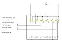
Diagram of the hook module - You need the wiring diagram of the hook module.

qqrqnapatyq 50769 37
ADVERTISEMENT
Treść została przetłumaczona polish » english Zobacz oryginalną wersję tematu
  • #1 16283677
    qqrqnapatyq
    Level 9  
    Hello,

    Does anyone have a diagram of a universal hook module that can, for example, be bought on Allegro?
    Alternatively, please explain the principle of operation.
    Does such a module only power a given channel so as not to overload the car's system, or does it have other additional functions?
    Could it run on transistors that just open and feed the channel directly from the battery?

    I have a hook connected in the car according to the current standard and the trailer is a bit crazy. There are no such problems in a car with a module. I suppose that the connection scheme in the trailer is different, and the module in the other car may be able to adapt to a different scheme. Is it possible?
  • ADVERTISEMENT
  • #2 16284521
    sadek1979
    Cars specialist
    diagram please (taken from alle ...) Diagram of the hook module - You need the wiring diagram of the hook module.
  • #3 16284535
    Pawel wawa
    VIP Meritorious for electroda.pl
    qqrqnapatyq wrote:
    In the car, I have a hook connected according to the current standard and the trailer is a bit crazy. There are no such problems in a car with a module
    Either the car requires a module or your connection is just wrong. No module "adapts" to the scheme of the trailer, it's total rubbish. What kind of car that you are in such trouble?
  • #4 16284801
    kryst
    Level 15  
    All trailers and trailers have the same plugs connected, first check in your socket (water and mud get there, maybe it's rotten).
  • #5 16285411
    grala1
    VAG group specialist
    It can work on transistors, but these transistors better control the relays.
    Special Features?
    It depends on the car because some of them have one 21W bulb for stopping and parking, where the driver in the car supplies the bulb with less power.
    In this case, the module should distinguish it and turn on the brake light bulb or ordinary light.
  • #6 16285480
    andrzej20001
    Level 43  
    You connect the stop signal for the module to the middle stop in the flap as you have 21W PWM controlled.
  • #7 16286234
    qqrqnapatyq
    Level 9  
    Tomasz Sadowski - thanks, but I meant a diagram for the construction of the circuit.

    Volvo V40, 1.9 TD 2003.

    The hook and socket are new, connected according to the diagram attached to the hook. Is there a rule by which you should connect the wires? I simply checked the back of the car with a meter where the voltage appears after pressing the brake, etc. and connected it to the socket.
    In the car socket, the mass is on one pin, and in the trailer, the mass is everywhere except for this pin. Should it be so that most of the pins from the trailer have a connection to the structure?
  • #8 16286385
    kryst
    Level 15  
    In the plug, you have a mess on each pin, because the bulbs short to ground and it should be so. It's best if you drive to someone, even to a gas station where they have trailers for rent or for castorama. At least I would check the socket like that.
  • ADVERTISEMENT
  • #9 16286529
    andrzej20001
    Level 43  
    If you measure it with a meter on the trailer, good luck.
  • #10 16289204
    qqrqnapatyq
    Level 9  
    Andrzej - I use the meter in the socket next to the car.

    I connected the wires from the bulbs in the rear lights, is it not the correct connection?
  • #11 16291264
    andrzej20001
    Level 43  
    Overall good luck with the meter :)
  • #12 16291578
    qqrqnapatyq
    Level 9  
    Do you think that the meter is not enough to find the current on the wires? Tell me more about what exactly you mean
  • #13 16291730
    rob4028
    Level 25  
    qqrqnapatyq wrote:
    I have a hook connected in the car according to the current standard and the trailer is a bit crazy

    can you explain this "freak"?
    I'd like to help you, but I don't know what the problem is ....
  • #14 16292941
    andrzej20001
    Level 43  
    qqrqnapatyq wrote:
    Do you think that the meter is not enough to find the current on the wires? Tell me more about what exactly you mean

    In high-current systems, I wish you good luck in finding the truth :) Unless you do everything from scratch and know what you are doing and how. I think so.
  • #15 16293417
    kryst
    Level 15  
    Are you sure you have bulbs or maybe LED lamps?
    qqrqnapatyq wrote:
    I connected the wires from the bulbs in the rear lights, is it not the correct connection?
  • #16 16294055
    qqrqnapatyq
    Level 9  
    Andrzej, thank you that you wish me good luck for the second time, but you think that the 12V that appears on the cable, for example after pressing the brake, is a distortion and is not there at all?

    rob4028
    I do not remember exactly what it looked like, but from what I remember it all seems ok. When I turn on the direction, everything seems to work, although maybe the other lights dim slightly. The problem is when I press the brake and then turn on the turn signal, from what I remember the direction is missing and similar with the fog light.

    There are definitely bulbs in the trailer.
  • #17 16294418
    kryst
    Level 15  
    I meant the car, because if you have LED lamps, they consume less electricity. It could be that there is no electricity for the trailer, a module would solve the problem.
  • #18 16294977
    qqrqnapatyq
    Level 9  
    The lamps are ordinary. From what I read, the module is not required, but as you write, the truth may be different and more power is needed.
  • #19 16295246
    abart64
    Level 33  
    You wrote in post 7 that you do not have weight on the pin where it should be. Check it in the plug, the mass must be on this pin.
    Perhaps in another car there is a weight on the trailer from the hook ball and then the trailer works fine.
  • ADVERTISEMENT
  • #20 16295285
    kryst
    Level 15  
    kryst wrote:
    In the plug, you have a mess on each pin, because the bulbs short to ground and it should be so.
  • #21 16295293
    abart64
    Level 33  
    qqrqnapatyq wrote:

    In the car socket, the mass is on one pin, and in the trailer, the mass is everywhere except for this pin.
  • #22 16296467
    qqrqnapatyq
    Level 9  
    abart64 in the car, mass and all voltage in the socket are ok (everything is correct when measured with the meter).
  • #23 16296536
    abart64
    Level 33  
    qqrqnapatyq wrote:
    abart64 in the car, mass and all voltage in the socket are ok (everything is correct when measured with the meter).

    The plug is usually in the trailer. I wrote "check in the plug" because you wrote that there is no mass on the pin.
  • #24 16301635
    qqrqnapatyq
    Level 9  
    Anyway, I meant that everything is fine on the car side :)
  • #25 16307084
    qqrqnapatyq
    Level 9  
    Will this module layout be correct?

    Relays
    songle-srd-12vdc-12v-10a-250vac-transmitter

    Diagram

    Diagram of the hook module - You need the wiring diagram of the hook module. [/ img]
  • ADVERTISEMENT
  • #27 16307862
    kryst
    Level 15  
    On each relay coil you need to give a rectifier diode. Otherwise something in the car will go with the smoke. Diagram of the hook module - You need the wiring diagram of the hook module.
  • #28 16307941
    qqrqnapatyq
    Level 9  
    kryst thank you very much, I already know why the relay failed in the simulation ;)
  • #29 16308097
    grala1
    VAG group specialist
    The failure of the relay has nothing to do with the lack of a diode.
    This protection is only to protect the electronics in the car and not to protect the relay.
  • #30 16308703
    qqrqnapatyq
    Level 9  
    So why does the relay blow up? As I added the diodes, it does not blow up now.

Topic summary

A user seeks a wiring diagram for a universal hook module compatible with trailers, specifically one available on Allegro. The discussion reveals that the module's function is to prevent overload on the car's electrical system and may include features like distinguishing between different bulb types. Several users suggest checking the trailer's socket for issues, as common problems include poor connections or incorrect wiring. The conversation also touches on the use of transistors and relays in the module's design, with recommendations for specific components like diodes to protect against electrical faults. The user shares their experience with a Volvo V40 and discusses the wiring discrepancies between the car and trailer. Various relay models and circuit designs are mentioned, along with suggestions for software to aid in circuit design.
Summary generated by the language model.
ADVERTISEMENT