logo elektroda
logo elektroda
X
logo elektroda

What closed profile should be used to withstand the weight of a person?

jawoks 83352 24
ADVERTISEMENT
Treść została przetłumaczona polish » english Zobacz oryginalną wersję tematu
  • #1 12555667
    jawoks
    Level 20  
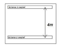
    I do not know what closed profile to use, which will be placed between 2 brick walls at a distance of 4 meters so that under the weight of a person standing in the middle of this profile it does not bend (let's assume 200 kg). It is best if it was a 80x80mm profile, such are available with wall thicknesses of 2.3 or 4 mm.
    I know that there are different patterns, but to be honest, I don't know how to use them, I just mean what profile can withstand this weight.

    What closed profile should be used to withstand the weight of a person?
  • ADVERTISEMENT
  • #2 12556308
    MALTIN
    Level 15  
    You can use profiles with a rectangular cross-section and a longer diagonal to arrange it vertically.
    I think 80x40x2 will be enough. I would even think about 60x40 (30) x2, depending on the price, because if there is a difference of PLN 2, it is not so bad. I personally walked the 40x40x2 profile on a similar span and hardly bent. But we are talking about more than 2 times that weight.
  • #3 12556419
    jawoks
    Level 20  
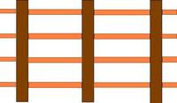
    Thanks for the answer. Generally, this profile cannot bend more than ~ 1mm, because currently the floor in one place is working too much and the tiles are cracking - the photo below shows everything:
    What closed profile should be used to withstand the weight of a person?
    If I buy it, the 80x80x2 / 3 mm profile, I just need to be sure that it will be enough
  • #4 12556536
    MALTIN
    Level 15  
    and not easier and cheaper to insert another beam?
  • #5 12556644
    jawoks
    Level 20  
    Unfortunately, there is no room for that anymore, the wooden beams are correspondingly much larger - I would like to do as little damage to the floor as possible.
    And steel is probably stiffer after all.
  • #7 12556766
    jawoks
    Level 20  
    It seems to me that the 80x80 closed profile will be stronger than the I-beam 80. Generally, I mean, let someone count the "deflection arrow" of this beam (I get strange results when I go for it) or say from experience that this beam is 4m will not bend under the weight of a person.
  • ADVERTISEMENT
  • #8 12556984
    Anonymous
    Anonymous  
  • #9 12557023
    jawoks
    Level 20  
    I don't know how you calculated it, but thanks a lot :)
  • #10 12557403
    saskia
    Level 39  
    Such stiffening of the ceiling is done differently.
    I don't know why everyone is blindly following the direction of the floor beams.
    If you add an additional beam (steel or wood), the beams will work independently anyway, which is what causes the tiles to crack.

    The floor beams you have there are sure to give you sufficient strength and you should rely on them, and stiffening the floor (s) is another matter.
    For the tiles, you need to create a uniform and rigid board based on the beams that are already there.
    It needs to be strengthened (stiffen with beams in pieces. :-) Oh yes, beams in pieces. :-)
    Such pieces when used properly give the same as an entire extra beam. :-)
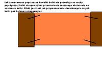
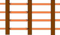
    I will try to make a drawing of a cross-section of such a stiffener.
    At construction sites, something like this is practically done on a daily basis to stiffen the ceiling.
    In the case of new ceilings, only 2-3 rows of replacements are made, which are made of waste pieces of beams.

    Added after 25 [minutes]:
    The following method, in addition to stiffening the ceiling, provides additional support points for panel joints.
    These exchanges do not have to be as thick as the ceiling joists, 4-5 cm is enough, but the height should be min. 2/3 of the height of the ceiling joists.
    Fasten preferably with screws, but nails hammered in alternately in different (opposite) directions (angles) give similar results. see figure 4.
    The replacements should be cut at an angle of 90 degrees, but you know, the old ceiling is slightly sagging and the beams are slightly twisted, so you mainly need to make sure that the ends of the replacements adhere to the ceiling joists at the top and bottom, without gaps.
    What closed profile should be used to withstand the weight of a person? What closed profile should be used to withstand the weight of a person? What closed profile should be used to withstand the weight of a person?
    What closed profile should be used to withstand the weight of a person?

    Added after 2 [hours] 6 [minutes]:

    jawoks wrote:
    It seems to me that the 80x80 closed profile will be stronger than the I-beam 80. Generally, I mean, let someone count the "deflection arrow" of this beam (I get strange results when I go for it) or say from experience that this beam is 4m will not bend under the weight of a person.

    A 100mm I-section with a span of 4m will have a deflection of about 12mm, which is more than a 22mm deflection of a plate, over a span of 80cm between the beams.
    Such a board needs a support of at least 60cm and 40cm. that is, if it is supported every 60 cm along its width, it must be supported every 40 cm along its length. I have already seen such boards supported reasonably well and a thin leg of a heavy piece of furniture passed right through it. :-)
    Besides, how do you want to fix the wood (boards) to steel, with glue?
    You're going to get a messier than you expect. Steel works differently than wood and the effect on the tiles will be worse than without it.

    A quicker and rather moderately good way is to use a flexible transition between the plate and the tiles (eastern glue), point gluing, and tiles of small dimensions, as well as givelarger than typical widths of the joints, which will reduce (spread) most of the stresses, but will not eliminate them completely.
    The support of the disc must be one way or another, only these replacements did not have to be that high.
    It is your decision, there is always something for something. The lower the quality of the stiffening, the greater the risk of damaging the tiles.
    You will make the stiffening solid, the plate will have good support and the plates will not crack.
  • #11 12558500
    Anonymous
    Anonymous  
  • #12 12558509
    saskia
    Level 39  
    It depends what type, but it is not essential. Even 7.5mm is too much. :-)
    The ceiling beam will be 0-2mm. :-)
    So there will be no good support on this steel beam, especially between two wooden ones. :-) The steel one works like a spring, and the wood damps vibrations (various resonances).
    It is enough to walk on such a steel beam. You have the impression that you are not going, but jumping up. :-)
    The author writes that the distance from the edge of one ceiling beam to the edge of the adjacent beam is 90 cm (spacing 110 cm), so I suppose these ceiling beams are about 25 cm x 50 cm, and such a beam does not have a deflection under human weight. :-)
    The problem is the space between them and the elimination of any movements between these beams.
  • ADVERTISEMENT
  • #13 12559318
    _jta_
    Electronics specialist
    The major component of strength is roughly proportional to the product of the height, width and thickness of the profile divided by the length; the side walls of the profile give an additional component ... together it is the formula H * d * (D + H / 3) / L, where d = thickness, D = width, H = height, L = length for the end load (for the load of the beam supported at the ends, the strength is 4 times higher), then it is necessary to multiply by the material strength factor (of the order of 100 kg / mm2 for steel - it can be from 40 to 150). So for 8cm x 8cm x 3mm, 4m supported at the ends and loaded in the middle: 80 * 3 * (80 + 80/3) /1000=25.6 mm2 - it will withstand at least a ton.

    Worse with the deflection assessment, this is where the main Young's modulus enters, for steel about 21000kG / mm2, i.e. under a load of tons, the steel will change the size by almost 1/500 of the length in the most loaded place - as much as the length changes by 2mm, this corresponds to a deflection of 2mm * 2m / 8cm = 50mm = 5cm; it really will be a bit smaller, with 3cm under the weight of a ton, i.e. 6mm under the weight of 200kg. I think the digiglobe mistook the unit, it was supposed to be 0.57mm, but 0.57cm ... or maybe I was wrong somewhere by a factor of around 10?

    I-section has a better strength-to-material ratio than a rectangular section of the same size and thickness - in the formula for strength, instead of H * d * (D + H / 3) / L will be H * d * (D + H / 6) / L, but for D = H an I-section has 3/4 of the material as a square profile - of course, as it lies as an I-section, not the letter H (the letter H has H * d * (H / 3) / L - for H = D 4 times less).
  • #14 12560081
    jawoks
    Level 20  
    Thanks for the comprehensive answers.
    saskia such "lattice" stiffeners as you write are the best solution, unfortunately now I would have to tear off the entire floor. Only in one place, as I showed, the floor works too much and the tiles move even though they are on elastic glue. Therefore, I am left with the installation of a steel profile.

    Today I bought a profile a bit stronger - 100x40x4mm 4m, I think it won't bend.
  • #15 12560145
    saskia
    Level 39  
    If these floor movements are only in one place, it is better to check these beams carefully.
    Beam damage is very likely. These can be wood pests, a fungus, or just a crack. You also have to check the ends embedded in the wall.
  • #16 12560162
    _jta_
    Electronics specialist
    Hopefully 100 will be vertical and 40 will be horizontal? Because the deflection depends on it (although the strength is not much).
  • #17 12560429
    jawoks
    Level 20  
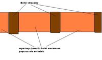
    Wooden beams are definitely ok, the reason for these bending osb boards is that in this place (where I want to install the profile) these boards connect, exactly between the supporting beams - as shown in the diagram above. This is also the weakest point.

    Yes of course 100mm will be vertical :)
  • #18 12561169
    saskia
    Level 39  
    It is not possible to give connections between beams and on the same beam.

    If you give all the connections of the plates to the steel one, you have a bank with all the plates cracking just as long as the connection is made. :-)
  • ADVERTISEMENT
  • #19 12561171
    _jta_
    Electronics specialist
    Well, joining the boards between the beams has the right to deform the boards and crack the tiles ... I think that this additional support at the connection point will remedy that. If you still have some space vertically, then put something on this profile (such as a plate, with a profile length and width of half a meter, even thinner than the floor ones - which will fit) - this will reduce the deformation of the floor in place joints under load next to it - the profile itself will only prevent a shift from the load at the joint.
  • #20 12561296
    saskia
    Level 39  
    jta, it won't do any good, linking will always be linking.

    Building elements cannot be treated as for example when calculating the deflection between two points.
    All the elements must be taken into account at the same time and how they work together and work together.
    The basic error here is the use of a 22mm OSB board with a span of 90 cm without additional support as a whole board, and this joining all the boards on one and such a different material beam is asking for more problems. :-)
    I wonder how this disc pad will prevent the disc from bending upwards? Because that's how the tiles crack. :-)

    The rest are just combinations that don't change anything.
  • #21 21543826
    AdrianDuda
    Level 6  
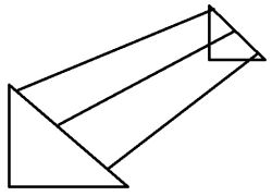
    What profile should I use so that the 6 m long hollow sections do not bend? I wanted to hang 3 photovoltaic panels on this, i.e. a weight of about 80 kg. Does this make any sense at all?
    Should I use 2 beams or 3?
    Schematic drawing of a triangular frame made of closed profiles, forming a mounting rack for photovoltaic panels. .
  • #22 21543893
    _jta_
    Electronics specialist
    Look on the manufacturer's website, e.g. Blachotrapez makes trapezoidal sheets for roofing and states their strength.
  • #23 21543932
    AdrianDuda
    Level 6  
    >>21543893 But I'm talking about hollow sections, not sheet metal, the panels would only be on steel beams.
  • #24 21543943
    _jta_
    Electronics specialist
    But I think the manufacturer gives the same information about durability - look for it on the manufacturer's website.
  • #25 21544293
    saskia
    Level 39  
    AdrianDuda wrote:
    What profile to use so that the 6m long hollow profiles do not bend? I wanted to hang 3 photovoltaic panels on this, so a weight of about 80kg. Does this make any sense at all?
    Use 2 beams or 3?
    Schematic drawing of a triangular frame made of closed profiles, forming a mounting rack for photovoltaic panels.
    .
    >>21543826 .
    Check where the support-mounting points are according to the panel assembly instructions, as this will determine how many beams you will need.
    And for a 6m span I'd advise giving the same triangular support to the beams in the middle as at the ends. 6m is quite a lot, too much distance for the structure to be stable.

Topic summary

The discussion revolves around selecting an appropriate closed profile to support a weight of 200 kg over a 4-meter span between two brick walls. Various profiles were suggested, including 80x80mm with wall thicknesses of 2.3mm or 4mm, and alternatives like 80x40mm and 100x40mm. Concerns about deflection were raised, with calculations indicating that a 80x80x3mm profile could deflect approximately 14mm under load. The importance of ensuring minimal bending to prevent damage to the floor and tiles was emphasized. Suggestions included using additional beams or stiffeners to enhance support, while also considering the structural integrity of existing wooden beams. The final choice made by the author was a 100x40x4mm profile, believed to provide sufficient strength without significant bending.
Summary generated by the language model.
ADVERTISEMENT