logo elektroda
logo elektroda
X
logo elektroda

BOSCH AL 3640 CV - Short circuit after connecting the charger to the power suppl

daro19862 36795 43
ADVERTISEMENT
Treść została przetłumaczona polish » english Zobacz oryginalną wersję tematu
  • #31 13561311
    daro19862
    Level 25  
    I put all the parts in the starting resistor, I gave 270 Ohm and the resistor from the 32 Ohm transistor, but the charger does not work.

    How to check if the inverter has taken the trick?
    The supply voltage of the converter is about 14-15V.

    I don't know why there is no voltage on the auxiliary winding of the transformer.
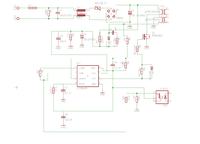
    I made a piece of the schematic:
    BOSCH AL 3640 CV - Short circuit after connecting the charger to the power suppl

    I replaced the diode and capacitor, but there is still no voltage.
  • ADVERTISEMENT
  • Helpful post
    #32 13561844
    cezarjak
    Level 19  
    daro19862 wrote:
    the starting resistor I gave 270 Ohm

    There should rather be as already 270 but Kom! yes, a colleague will damage the system again,
    daro19862 wrote:
    I don't know why there is no voltage on the auxiliary winding of the transformer.

    Because the converter does not work, as the transformer is supposed to produce voltage there, the starting resistor only 'initiates' the converter and then the auxiliary winding is responsible for the power supply. Either there is a short circuit on the capacitors after the secondary or damage to the primary one.
    Does the inverter start for a fraction of a second? what is the output voltage at the moment of switching on? maybe something is overloading the inverter
  • ADVERTISEMENT
  • #33 13562273
    daro19862
    Level 25  
    I was wrong in spelling of course there is a 270 K Ohm starting resistor.
    How can I check if the converter starts for a fraction of a second?
    Should I check the output voltage on the leg 6 of the inverter?
  • #34 13562331
    cezarjak
    Level 19  
    On the secondary side, after the transformer and the diode on the capacitor, there is no 3-pin tl431 or something similar next to the optocoupler?
  • #35 13562390
    daro19862
    Level 25  
    There is WL431 the first and third leg are connected by a path, but it is probably from the loudspeaker because when I check it with a meter, the speaker in the charger sounds.
  • #36 13563510
    daro19862
    Level 25  
    Can it not work because instead of 190k ohm I put 270k ohm? I do not have 190k Ohm, and can I connect 2 resistors in series, e.g. 160k and 30k?

    There is no short circuit on the secondary side.

    No voltage at the output of the inverter.

    The transformer has 2 windings on the primary side, one thick which is connected through the P6NK90Z transistor (I understand that the output signal from the converter that goes to the P6NK90Z gate makes this transistor conductive?)

    The second lean path winding is connected via a capacitor and the resistor I do not really understand what the converter has to do with this winding, in total there is a 27k Ohm resistor in the diagram, it looks like this:
    BOSCH AL 3640 CV - Short circuit after connecting the charger to the power suppl
    I just do not know which way the current flows, or from the 3 Current Sense leg of the inverter through the 27k resistor to the primary auxiliary winding, or from the primary auxiliary winding through the 27k resistor to the 3 Current Sense leg of the inverter?
  • #37 13570976
    daro19862
    Level 25  
    I made a diagram of the primary part of the charger:
    BOSCH AL 3640 CV - Short circuit after connecting the charger to the power suppl

    The voltage on the legs of the converter is 0.1V in addition to the power supply, I only saw that instead of UC3842B, the seller sold me TL3482P

    Will anyone be able to suggest something now with a piece of the schematic?

    Added after 1 [hours] 6 [minutes]:

    After connecting 160k and 45k in series, the charger comes to life as a starting resistor, the green LED is on, and when the battery is inserted, the LED blinks.

    Thanks to everyone for your help.
  • ADVERTISEMENT
  • #38 13571561
    cezarjak
    Level 19  
    My colleague, I am glad that there is progress, but my colleague needs to learn the basics of the inverter's operation, the current sense leg is used to explain in a blatant way as an overload protection and measures the voltage on the resistor which is between the transistor and ground and is usually below the ohm, the output leg, i.e. transistor control , VCC we know the power supply and here the system is first powered by the resistor and after starting from the auxiliary winding, this leg is usually a zener diode, voltage feedback is a kind of feedback which pulses are taken from the optocoupler which is connected to the converter output and stabilized the voltage of the inverter under different load. Simply put, the inverter thus keeps the voltage constant in this way.
    As for the fact that the diode is blinking, i.e. the converter either has no power or there is a short circuit somewhere further, you also need to check whether the system is actually interchangeable.
  • #39 13571866
    daro19862
    Level 25  
    The diode is blinking because it probably should only blink when the battery is inserted. And this is how it all works because the battery is charged.
  • #40 13572059
    cezarjak
    Level 19  
    And how do I understand it, although I do not know what the charging process should look like in this charger, and after finished charging, does the green LED light up continuously?
    Or maybe it goes out, it would mean that the charger is already operational, but unfortunately I do not know if it is correct, but since it has charged the battery it is ok. I am glad that I could help and that the repair was finished.
  • #41 13572266
    daro19862
    Level 25  
    The charger blinks when I charge the battery and when it is already charged, it beeps 2 times and the LED is on. I read in the manual that it must be so.
    I do not know what to do with 2 resistors, the first one should have 30 Ohm that goes to the gate of the transistor, I did not have 30 Ohm, I put 32 Ohm, I do not know if these 2 ohms will not cause damage. Also, instead of 190k ohms, I put 160k ohms and 45K ohms in series, which gives a total of 205K ohms.

    @Edit
    I would like to add that after connecting to the network, the charger lights up the diode only after 2-3 seconds, I do not know if this is normal or not.
  • #42 13572284
    cezarjak
    Level 19  
    You can leave it like that, which is all right, and so I will ask, buddy, what was it that the inverter did not start?
    Congratulations on your persistence and I think it paid off, my friend learned something and repaired the equipment. Regards.
  • #43 13572302
    daro19862
    Level 25  
    The converter did not start because the starting resistor had too high resistance, at the beginning 270K Ohm was sitting there and the charger did not want to work, after replacing it with 205K Ohm, the charger started working.

    Thank you again for your persistence and patience. GREETINGS
  • ADVERTISEMENT
  • #44 18267157
    wieniufa
    Level 12  
    The original value of this resistor is 170 k?.

Topic summary

The discussion revolves around troubleshooting a BOSCH AL 3640 CV charger that experienced a short circuit after a user attempted to bypass a missing fuse. The user discovered a damaged thermistor (NTC 100-11) and several other components, including diodes and a MOSFET transistor, which were also found to be faulty. Various responses provided guidance on testing and replacing components, including the use of a light bulb to prevent further damage during testing. The user successfully replaced several parts, including the UC3842B chip, and adjusted resistor values to restore functionality. Ultimately, the charger began to operate correctly, indicated by a blinking LED during battery charging and a steady light when fully charged.
Summary generated by the language model.
ADVERTISEMENT