logo elektroda
logo elektroda
X
logo elektroda

FAAC 414 Actuator & E045 Control Panel Cable Connection: Terminal 1-6 Guide & Photocell Setup

Gruchalublin 95325 15
ADVERTISEMENT
Treść została przetłumaczona polish » english Zobacz oryginalną wersję tematu
  • #1 14732689
    Gruchalublin
    Level 9  
    Hello

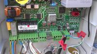
    I need help with the correct connection of the cables in the FAAC E045 control panel for actuators and starting capacitors.

    The following cables come out of the actuators:
    -Green / Yellow
    -Black
    -Gray
    -Brown
    I have two unmarked cables in the capacitor.

    According to the instructions, I connect the blue or gray cable from the first actuator to terminal 1, and other cables to 2 and 3. My question is which cable where and to which clamp to connect the capacitor cables?

    The situation is similar with the second actuator, which is connected to terminals 4,5,6. I know that I should connect gray or black to 4.

    I have only one pair of photocells installed in the system. All jumpers in both photocells are ON. Is there anything else I should bridge or set for the system to work properly? I would like to add that the photocells are connected to the BUS-2EASY socket.

    I am asking for a pathological explanation of the connection method.

    greetings


    [/ youtube]


    .................................................. ..........................
    Announcement


    We invite you to read the guides, highlighted topics, articles in the field of security systems such as intercoms, gate and barrier automation, alarm systems, cameras, access control:
    Security Systems Tutorials


    If you do not find the answer to your question in the above-mentioned topics, please visit the forum:
    Security systems


    We also encourage you to visit the General Guides section, where you will find materials from other forum sections, including those for people starting their adventure with electronics:
    General Tutorials
  • ADVERTISEMENT
  • Helpful post
    #2 14732901
    kotbury
    Gantry automation specialist
    Well, read the instructions carefully ...
    You connect condenastors to 2,3 and 5,6
    The yellow and green cables from both actuators are connected to the PE terminal on the power supply cube (first from the left).
    The gray or blue cables from the actuators are connected to terminals 1 and 4
    The remaining actuator cables (i.e. brown and black) are connected to the capacitors, respectively. You can check the correctness of the connection with the + and - buttons in the switchboard. You position the wings in the middle of their stroke and without entering any menu, press +, then -, the left and right wings should start to close, respectively. As they open, swap brown and black on both cylinders. (gray or blue stiff in 1 and 4)
    Pics wrong. When closing, they should be On Off Off Off (set when the power is off) then after turning on the power, perform the BUS accessories detection procedure - chapter 5.3.

    I should also bridge 11 and 16, i.e. stop with a minus, otherwise the gate will not move at all.
    Then you have to do time assimilation.
    EVERYTHING IS IN THE MANUAL.
  • #3 14735001
    Gruchalublin
    Level 9  
    Approx
    The cables from the actuators and capacitors are connected correctly, the remote control is programmed.

    Now I'm trying to do a time absorbtion. I set up bumpers in the middle of the gate with the wings closed and the wings open.
    1) I close the wings
    2) I press R1 and R2 starts the first wing, after reaching the limiter I press the button on the remote control, then the second wing, after reaching the buffer, I press the button, the second wing closes and then the first one. I UNDERSTAND THAT THE CONFIGURATION ENDED SUCCESSFUL, the display shows 00.

    This is where the problems begin. At the first attempt to open the gate (with or without bumpers), both leaves open to the maximum, i.e. the actuators fold completely and begin to hum and the dowels are torn off the posts. The gate does not stop at the programmed position. I am not able to check if the situation repeats when closing because I am afraid that it will burn the actuators and turn off the power.

    Please help!!!


    kotbury wrote:
    Well, read the instructions carefully ...
    You connect condenastors to 2,3 and 5,6
    The yellow and green cables from both actuators are connected to the PE terminal on the power supply cube (first from the left).
    The gray or blue cables from the actuators are connected to terminals 1 and 4
    The remaining actuator cables (i.e. brown and black) are connected to the capacitors, respectively. You can check the correctness of the connection with the + and - buttons in the switchboard. You position the wings in the middle of their stroke and without entering any menu, press +, then -, the left and right wings should start to close, respectively. As they open, swap brown and black on both cylinders. (gray or blue stiff in 1 and 4)
    Pics wrong. When closing, they should be On Off Off Off (set when the power is off) then after turning on the power, perform the BUS accessories detection procedure - chapter 5.3.

    I should also bridge 11 and 16, i.e. stop with a minus, otherwise the gate will not move at all.
    Then you have to do time assimilation.
    EVERYTHING IS IN THE MANUAL.
  • ADVERTISEMENT
  • #4 14735280
    kotbury
    Gantry automation specialist
    Basically everything ok. This is how the Faac 414 actuators work - the wings hit the bumpers and the actuators hum for a few seconds - this is a normal condition and the actuators will be fine - so that the work on the blockade does not last longer than 3-4 seconds. (reserve for thick grease in winter, rusty hinges, etc.). Are the layoffs well positioned or are they so spread out that they are gone?

    I have some experience with the 452/455 control panels and there, too, the times were first set manually (here in 045 there is only an automatic machine) and not an automatic machine, and secondly, they were very indicative. I suspect 045 is similar. Hence the categorical recommendation to use bumpers on the wings.
    You can shorten the time of "humming" by signaling that the wing reaches the stop immediately after touching it or even a little earlier, the machine will add its own .... If the decelerations are also indented or are too short - just before the bumps - you can modify them - parameters r1 and r2 in the advanced settings.
    The use of encoders on the actuators would slightly improve the situation (but only slightly - the precision of the times would still be average, the only big benefit from their installation is the appearance of the obstacle detection function on the wings) but it costs PLN 200 per actuator and the need to bring two additional cables to the actuators.
  • #5 14735298
    Gruchalublin
    Level 9  
    Hmmm
    Indeed, after a while, the actuators turn off after hitting the bump stops on opening, but after pressing the button to close the gate, nothing happens.
    There is a code 03 on the control panel, meaning "stopped, then closes".

    I press a button on the remote and nothing happens.
    I thought maybe something with a photocell and checked its condition. In the bu function, the state looks like this _ - that is, the first dash is only on the bottom and the second dash in the middle.

    Added after 1 [minutes]:

    the slowdowns begin after opening a little more than half of the gate's movement. Set up from the beginning, I didn't set it up myself.
  • Helpful post
    #6 14735363
    kotbury
    Gantry automation specialist
    If the photos are not covered (and you have only one set for closing), in the check by the bu function, the left display is to be off, only the middle dash on the right. If you cover the photos (and they are set as I wrote you - on closing, i.e. on off off and finally the same on the transmitter and receiver), the lowest segment on the left digit should only light up.
    At the same time, the red LED DL15 (at the BUS socket) should light up when covering the photos, and the green LED, signaling the correct state of the line, should be on continuously.
    As long as this segment is burning, it will be "_-" and not "-" the gate cannot be closed. Check the cables from the photos, maybe they are just wrongly positioned and can't see each other?
    Check the settings of the switches on the transmitter and receiver, they should be the same, do the detection again.

    Check the setting of the LO parameter in the basic - it should be EP, i.e. open-stop-close-stop.
    You can change the exemptions by editing r1 and r2 as I wrote earlier.

    As with the photos, you do not coil anything (dead or loose cable somewhere under the ground), disconnect the cable from the board at all and do bus detection - the gate will go without.
  • #7 14736597
    Gruchalublin
    Level 9  
    The actuator programming is exactly as you write.
    We start programming on the closed gate, then give the signal to stop the opening of the leaves much earlier than they are to actually open (for me it is about 60 cm earlier). We give the signal to stop the leaves when closing exactly at the point where the leaves are to stop. The matter of trial and error, after about 6 programming attempts, I managed to set such a range of movement in which the gate can operate without mechanical stops.
    Unfortunately, the matter becomes more complicated when the photocell signal is cut while the gate is closing. The control unit stops the gate and the leaves begin to open unfortunately for the time programmed for complete opening from the gate closing point, which results in the gate opening to its maximum position and the motors hum for the rest of the working time.

    The conclusion is that only one gate must be fitted with mechanical stops when opening the gate, not necessarily when closing. If someone does not want to install mechanical stops, he must resign from installing any devices that may interrupt the operation of the leaves during movement, e.g. photocells.

    I hope the topic is exhausted :-)

    Now I have another problem, namely how to connect Normsthal remotes from the garage door to operate the FAAC entrance gate? I know that you need to buy a special module, can you recommend something and describe how to do it?
  • #8 14737420
    kotbury
    Gantry automation specialist
    You buy a receiver compatible with Normstahl, e.g. a damn expensive original: http://automacik.pl/akoszenia/odbiorniki_radi...nik_uniwersalny_normstahl_24v_2-kanalowy.html or a three times cheaper Proxim NW2 replacement in the Normstahl version (the version is agreed upon when ordering).
    Power from J9 and the output - radio relay contacts under Open A (J9) and minus (J3)

    So the photos have started? As for getting lost, it is enough to use the remote control several times in a row in the middle of the movement, it will get lost and on closing. The only way out then is to go through a full cycle of opening and closing. Encoders on the actuators would change the situation, but as I wrote - additional cables and additional cash.

    Ps. The bump in the middle of the gate on the closing is as recommended as possible - apart from timing issues, it stiffens the closed gate (the gate does not shake from the wind and drunks)
  • ADVERTISEMENT
  • #9 14739043
    Gruchalublin
    Level 9  
    So the photocells moved without any problem. Today I will mount the bumpers and post a few photos, maybe someone will have similar doubts when installing actuators as I do.

    I should have no objections to the FAAC 414 set and the E045 control unit, because all the problems resulted more from my ignorance than a malfunction of the set, but yesterday I talked to a neighbor who has NICE actuators and from what he described he is more friendly to installation and correct programming than mine.
    Its set works without limiters and the possibility of manual programming and adjustment of the wings is a good solution, I either manage to stop the wings in the desired place or repeat the configuration procedure again.

    greetings
  • #10 14966177
    streser
    Level 1  
    I will stick to the topic. I have the same kit, but the actuators won't budge. I connected it as simply as possible, i.e. only motors with capacitors and 11-15 jumper, the DL7, DL16 and DL17 LEDs on the display do not light up and pressing + or - does not cause any reaction. I don't really see what you can do wrong here and it doesn't work. FAAC 414 Actuator & E045 Control Panel Cable Connection: Terminal 1-6 Guide & Photocell Setup
  • #11 14967262
    edziu
    Level 29  
    If nothing is lit on the display, you have a faulty control panel (display)
    after connecting the control panel to the network, wait 10sec
    press F (setup) 12 times
    and on, see manual page 26 type of learning time.
  • #12 14970316
    starter55
    Level 24  
    Hello,
    I will ask such a question,
    What are the costs of installing such a set on a double-leaf gate and
    What is the best set to choose? actuators? what electromagnetic lock? the budget without assembly is about PLN 1600
    double-leaf gate, one leaf, about 80-100 kg, length 2.6 meters.
    Greetings.
  • #13 15047351
    QazazaQ
    Level 2  
    Hello
    I have the same switchboard and I have 11 and 15 bridged
    A colleague wrote a few posts above that you need to bridge 11 and 16
    My question is whether this bridge needs to be replaced or can it be?
  • #14 15047398
    kotbury
    Gantry automation specialist
    15 and 16 are the same minus (ground) of the accessories and are short-circuited. Please - run your brains and watch the instructions carefully.

    So --- IT CAN STAY
  • #15 15763612
    starydekorpak
    Level 11  
    and how to check if the actuator is operational
  • ADVERTISEMENT
  • #16 15764604
    kotbury
    Gantry automation specialist
    Directly to 230 V go. (Careful - the web can kill)
    So gray (common - com) to network zero. Directional (i.e. usually black and brown) connect with a capacitor and touch the brown or black one with the phase. The actuator should extend or retract. If it just buzzes, first buy a new capacitor in the electrician (it does not have to be the original one, it will be enough if it will have the same parameters), if you still have nothing to measure, give it to the electronics engineer - the stator may have shorted windings or, more prosaically, a worn power cable. The cable can be replaced, the stator can be purchased at a moderate price (less than PLN 100) - it is rather not profitable to rewind, especially since the original has a very effective thermal fuse.
    A mechanical failure is also possible - a broken gear or damaged clutch release (the engine is spinning - you can feel vibrations and the actuator does not extend) but they occur extremely rarely.

Topic summary

The discussion revolves around the correct cable connections for the FAAC 414 actuators and the E045 control panel, specifically addressing the wiring of actuator cables and capacitors. Users seek guidance on connecting the green/yellow, black, gray, and brown cables from the actuators to the control panel terminals, as well as the setup of photocells. Several responses provide detailed instructions on connecting the cables to terminals 1-6, bridging necessary terminals, and troubleshooting issues related to actuator movement and photocell functionality. Users also share experiences with programming the actuators and adjusting settings to ensure proper operation without mechanical stops. The conversation highlights the importance of correct wiring, programming, and the use of bumpers for optimal gate operation.
Summary generated by the language model.
ADVERTISEMENT