One very good method of filtering high frequency interference and noise from the power line, especially when it is shared between multiple circuits - digital and analog - are ferrite beads. These are passive components that help to filter out some of the high-frequency noise for which they present a fair amount of resistance and dissipate the noise energy as heat. It is connected in series with the device in the supply line along with a filter capacitor to ground (either side of the bead). Such a system forms a low-pass filter, which additionally helps to filter out disturbances from the power line of a given system.
Of course, as in any case, incorrectly selecting ferrite beads may not help filter the feed lines or may have negative effects. An example of this may be additional resonances that occur between the bead and the filtering capacitor or the incorrect selection of this element to the current that is to flow through it, which translates into reduced interference suppression efficiency. In order to correctly use this element in your electronic systems, it is necessary to understand its basic parameters - thanks to this, it will be possible to avoid mishaps with the selection and use of this element.
In the article below, we discuss important issues related to the design of power filtering systems using ferrite beads. We will focus on the analysis of impedance as a function of the frequency of this element with variable DC polarization and undesirable LC resonances that may arise in the system. Finally, we will get acquainted with the techniques of using beads to suppress interference in power lines and we will compare the basic features of several power filter architectures.
The use of beads will be discussed on the example of an output filter from a DC-DC converter with a current capacity of 2 A and two independent voltage outputs - positive and negative. This converter is based on the ADP5071 chip, and the ferrite beads used are usually surface mount components (SMD).
Simplified model and simulations of a ferrite bead
The ferrite bead can be modeled using the equivalent diagram consisting of a resistor, inductance and capacitance as shown in Figure 1a . The RDC resistor is responsible for the DC resistance of the element, CPAR is the parasitic capacitance of this element, LBEAD is the bead inductance, and RAC is the resistance related to the saturation of the core when working with alternating voltage.

Fig. 1. (a) A simplified replacement diagram for a ferrite bead. (b) Tyco Electronics BMB2A1000LN2 impedance measurement result.
Ferrite beads are characterized in three ranges - inductive, resistive and capacitive. It is easy to distinguish them by looking at the bead impedance graph shown in Figure 1b . The diagram shows the impedance (Z), resistance (R) and reactance (X) of the bead as a function of frequency. The best filtering performancenoise is achieved for disturbances in the resistive range of the bead, especially when we want to filter electromagnetic disturbances. In this range, this element acts as a resistor, blocking the signals from flowing in a certain frequency range. The resistive range is defined as the frequency range from where X = R to where -X = R. Below the frequency in this range, the bead is in the inductive range and above in the capacitive range.
In a number of cases, the simplified ferrite bead model can be used up to hundreds of MHz.
Tyco Electronics' multi-layer BMB2A1000LN2 bead was selected as an example to be discussed in this article. On Figure 1b presents a diagram of the impedance of this element with zero polarization with a constant current.
For the inductive range where the impedance is approximately equal to $$X_L$$ The bead inductance can be determined using the following formula:
where f is the frequency in the inductive range - in our case f = 30.7 MHz, and XL is the reactance at this frequency, equal to 233?. The equation shows that the inductance of this bead is 1.208 uH.
For the capacitive range where the impedance is approximately equal to $$|X_C|$$ , we find the parasitic capacity using the equation:
where f is the frequency in the capacitive range - in our case f = 803 MHz, and | XC | is the reactance at this frequency, equal to 118.1 ?. The equation shows that the capacity of this bead is 1.678 pF.
The bead's DC resistance is 300m? and we can find it in the catalog card of the element. The AC resistance is the maximum impedance at the point where the behavior of the bead is purely resistive. To find this value, we have to subtract the value of the DC resistance RDC from the impedance Z, which gives us the results of 1.082 k?.
By having the values of the individual elements in the replacement diagram, we can model the behavior of the bead. For this purpose, you can use, for example, the ADIsimPE tool for simulating circuits, using SIMetrix / SIMPLIS. This allows you to generate a plot of impedance versus frequency. On figure 2a the model used for the simulation is presented, and on figure 2b shows the determined theoretical curve and the measured impedance as a function of frequency. The compliance of the measurement with the calculations is very good.

Fig.2. (a) Equivalent diagram of the modeled bead, (b) Comparison of the measured and modeled impedance value as a function of frequency for the discussed bead.
The ferrite bead model can be very useful when designing and analyzing circuits with such elements. For example, by approximating a bead as inductance, it is easy to determine the bead's resonant cutoff frequency when it is in a circuit with a filter capacitor, forming a low pass filter. However, the presented model only works properly with zero DC polarity. If we want to use it for a DC polarized element, we have to use a more complicated model.
The influence of direct current polarization
Choosing the right ferrite bead for a given application requires not only an analysis of the system's filtering bandwidth, but also the influence of the bead's DC polarization on the impedance characteristics as a function of frequency. In most cases, manufacturers only provide the bead impedance specification for 100 MHz and present the impedance spectra at zero DC polarization. However, when we use a bead to filter the power, a current flows through it to power the device, and as it increases, the parameters of the bead change significantly.
As DC flow increases, the bead core material begins to saturate, thereby reducing the bead inductance. How much the core will saturate at a given current depends on what material it is made of. Figure 3a shows the typical behavior of two sample beads for polarization with different currents. For polarization with a current of 50% of the maximum, the inductance of the element is reduced even by 90%.
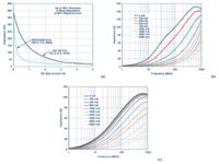
Fig. 3. (a) The influence of the polarization current on the inductance and impedance of the bead for the beads: (b) TDK MPZ1608S101A and (c) Würth Elektronik 742 792 510.
To ensure efficient filtering of power noise, it is recommended to use the bead at a current of about 20% of the maximum. As shown in the graphs, at 20% of the maximum current, the inductance drops to about 30% for a 6 A bead and 15% for a 3 A bead. parameter indicating the current at which the bead should work continuously.
Additionally, the influence of DC polarization manifests itself as a decrease in the impedance value for all frequencies, which translates directly into a reduction in the bead's effectiveness in suppressing EMI disturbances. On figures 3b and 3c shows how the ferrite bead impedance changes for different DC polarities. After already applying 50% of the maximum current, the effective impedance at 100 MHz drops from 100? up to 10 ? for TDK MPZ1608S101A bead (100?, 3 A, 0603) and with 70? to 15? for Würth Elektronik 742 792 510 (70?, 6 A, 1812) bead.
Summarizing this part, it must be repeated that when designing a power system and choosing a bead for a specific application, it is necessary to choose it taking into account the current that is to flow through it. For optimal EMI suppression efficiency in the power line, it is best that the current does not exceed 20% of the maximum value for the component.
LC resonance effects
Resonance may occur when the system incorporates both a ferrite bead and a power filtering capacitor. This is an often overlooked or neglected effect, however, it can amplify - rather than suppress - line noise in a certain frequency range. It happens that this range coincides with the operating range of the DC-DC converter in the system, which, as you can easily guess, is a ready recipe for a very poor quality power supply to the system behind the bead and capacitor.
Unwanted phenomena occur when the resonant frequency of the low-pass filter composed of the ferrite bead inductance and the high Q filter capacitance is below the bead frequency. In this situation, the filter does not suppress the noise as much as shown in figure 4 in the graph of impedance versus frequency for the TDK MPZ1608S101A bead. The resistance on which the signal scattering depends does not have a significant value up to the frequency of 20..30 MHz, below this frequency the bead has a high goodness and behaves like an ideal inductance. The LC resonance frequency for a typical bead is 100kHz to 10MHz and the typical inverter switching frequencies are 300kHz to 5MHz. In a situation where these two frequencies coincide in the designed system, additional noise suppression is necessary to reduce the filter goodness.

Pic.4. (a) Graph of impedance as a function of frequency for A bead TDK MPZ1608S101A, (b) Graph of the gain of the low-pass filter consisting of a capacitor and a ferrite bead.
On figure 4b An example of the situation described above is presented, which manifests itself in the form of a gain maximum near the cutoff frequency. TDK MPZ1608S101A ferrite bead (100?, 3A, 0603) and Murata ceramic capacitor GRM188R71H103KA01 (10nF, X7R, 0603) were used. The system was loaded with several microamperes during the measurement.
The undamped filter composed of a bead and a capacitor has maxima of about 10 dB to 15 dB, depending on the filter quality. On figure 4b the diagram shows that at a frequency of about 2.5 MHz, the filter gain increases to about 10 dB.
In the wider spectral range, from 1 MHz to 3.5 MHz, you can also see how the filter amplification is arranged. The phenomenon described above is particularly harmful if the system is to filter the voltage from a pulse converter operating in this frequency range or for systems sensitive to interference of a specific frequency - phase-coupled loops (PLL), voltage controlled oscillators (VCO) or precise analog-to-digital converters with high definition (ADC). The measurement results presented in figure 4b were obtained for a small load of a few microamperes, but in a realistic case the current consumption will be at the level of a few milliamperes or more, which means an increase in the significance of the described phenomenon and the possibility of e.g. crosstalk between devices operating on one power line.
Picture nr 5 shows an example application - the ADP5071 chip - with a ferrite bead at the output. On Figure 6 the voltage spectrum from the positive output is presented. The switching frequency is 2.4 MHz and the input voltage is 9 V. The output voltage is 16 V and the output current is 5 mA.
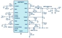
Pic.5. Converter based on ADP5071 with a ferrite bead as part of the output filter.
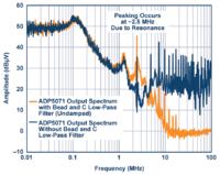
Pic. 6. Spectrum of the output voltage from the ADP5071 with a current consumption of 5 mA.
Resonance in the filtering system occurs at a frequency of about 2.5 MHz, due to the bead inductance and the capacitance of the ceramic capacitor in the filter - 10 nF. Instead of attenuating the interference from the converter at 2.4 MHz, a gain of 10 dB is observed.
Other factors influencing the formation of resonances are the series impedances and the loads that are seen through the bead. The above-described effect is strongly suppressed if the impedance of the power source is high, however, in this way the precision of voltage stabilization decreases, which is effectively not a practical method. On the other hand, at low load impedance, the effect is significantly suppressed.
Methods of resonance suppression
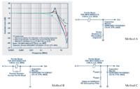
This section provides a practical description of how to suppress resonances in ferrite bead filter circuits. Look figure 7 . Three methods are described below - A, B, and C.
Method A is based on adding a series resistor to the circuit, which will suppress resonance, but also - unfortunately - limit the attenuation by bypassing the high frequency filter.
Method B it consists of adding a small resistor in parallel with the ferrite bead. In this situation, high frequency filter attenuation deteriorates as shown in figure 8 . It presents a graph of the filter impedance as a function of frequency for the MPZ1608S101A bead with and without a 10? Resistor.
Method C is based on the addition of high damping capacity (CDAMP) with a series resistor (RDAMP) - most often this is the optimal solution. The addition of a resistor with a capacitor does not deteriorate the noise suppression properties of the system, and at the same time suppresses the filter resonance. The CDAMP capacitor prevents excessive heat emission on the RDAMP damping resistor, as no direct current flows through it, cut off by CDAMP capacitance. The capacity of the CDAMP capacitor must be significantly greater than the sum of all filter capacitors. As a result, the resistance value of the RDAMP resistor can be small.
On Figure 9 presented the spectrum of the output from the ADP5071 converter with the implemented C-type damping circuit, which gives a significant improvement in relation to the spectrum shown in Figure 5 . This circuit uses a ceramic CDAMP capacitor with a capacity of 1 F and a RDAMP resistor with a resistance of 2 ?. Thanks to the use of this system, the interference with a frequency equal to 2.4 MHz (switching frequency of the converter) is suppressed by 5 dB, and not amplified by 10 dB, as in the original case.
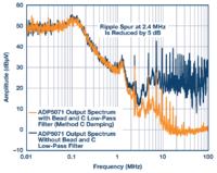
Fig. 9. Spectrum of the output signal from ADP5071 with bead and filter capacitor, using method C of resonance suppression.
In general, method C is the best and should be implemented as often as possible. Thanks to the use of separate discrete elements, instead of an expensive dedicated damping capacitor, which also has a positive effect on the cost of such a solution. Thanks to the use of discrete elements, it is also possible to adjust the values of CDAMP and RDAMP elements to the needs of the system at the stage of system prototyping.
Summary
The above material describes the key aspects of the use of a ferrite bead along with the phenomena behind it, as well as a model - a substitute diagram - of the bead along with information on how to characterize this element. The model shown shows good agreement with the experimental results.
The article describes various details related to the use of ferrite beads, e.g. the influence of the polarization current on its operation and the formation of resonances in the spectrum due to the LC resonance in the filtering system. The methods presented above make it possible to adequately reduce the impact of these phenomena on the operation of the filter.
As the ferrite bead is inductive, it should not be used with high Q capacitors without careful analysis of the situation. This situation can generate resonance peaks, whichit translates into a significant deterioration of the interference filtering ability in the system, especially when the resonant frequencies coincide, for example, with the switching frequency of the DC-DC converter or the sampling frequency of the ADC converter.
Source: http://www.analog.com/library/analogdialogue/archives/50-02/ferrite-beads.HTML
Of course, as in any case, incorrectly selecting ferrite beads may not help filter the feed lines or may have negative effects. An example of this may be additional resonances that occur between the bead and the filtering capacitor or the incorrect selection of this element to the current that is to flow through it, which translates into reduced interference suppression efficiency. In order to correctly use this element in your electronic systems, it is necessary to understand its basic parameters - thanks to this, it will be possible to avoid mishaps with the selection and use of this element.
In the article below, we discuss important issues related to the design of power filtering systems using ferrite beads. We will focus on the analysis of impedance as a function of the frequency of this element with variable DC polarization and undesirable LC resonances that may arise in the system. Finally, we will get acquainted with the techniques of using beads to suppress interference in power lines and we will compare the basic features of several power filter architectures.
The use of beads will be discussed on the example of an output filter from a DC-DC converter with a current capacity of 2 A and two independent voltage outputs - positive and negative. This converter is based on the ADP5071 chip, and the ferrite beads used are usually surface mount components (SMD).
Simplified model and simulations of a ferrite bead
The ferrite bead can be modeled using the equivalent diagram consisting of a resistor, inductance and capacitance as shown in Figure 1a . The RDC resistor is responsible for the DC resistance of the element, CPAR is the parasitic capacitance of this element, LBEAD is the bead inductance, and RAC is the resistance related to the saturation of the core when working with alternating voltage.

Fig. 1. (a) A simplified replacement diagram for a ferrite bead. (b) Tyco Electronics BMB2A1000LN2 impedance measurement result.
Ferrite beads are characterized in three ranges - inductive, resistive and capacitive. It is easy to distinguish them by looking at the bead impedance graph shown in Figure 1b . The diagram shows the impedance (Z), resistance (R) and reactance (X) of the bead as a function of frequency. The best filtering performancenoise is achieved for disturbances in the resistive range of the bead, especially when we want to filter electromagnetic disturbances. In this range, this element acts as a resistor, blocking the signals from flowing in a certain frequency range. The resistive range is defined as the frequency range from where X = R to where -X = R. Below the frequency in this range, the bead is in the inductive range and above in the capacitive range.
In a number of cases, the simplified ferrite bead model can be used up to hundreds of MHz.
Tyco Electronics' multi-layer BMB2A1000LN2 bead was selected as an example to be discussed in this article. On Figure 1b presents a diagram of the impedance of this element with zero polarization with a constant current.
For the inductive range where the impedance is approximately equal to $$X_L$$ The bead inductance can be determined using the following formula:
$$L_{koralik} = \frac{X_L}{2 \times \pi \times f}$$ (1)
where f is the frequency in the inductive range - in our case f = 30.7 MHz, and XL is the reactance at this frequency, equal to 233?. The equation shows that the inductance of this bead is 1.208 uH.
For the capacitive range where the impedance is approximately equal to $$|X_C|$$ , we find the parasitic capacity using the equation:
$$C_{pasozytnicza} = \frac {1}{2\times \pi \times f \times |X_C|}$$ (2)
where f is the frequency in the capacitive range - in our case f = 803 MHz, and | XC | is the reactance at this frequency, equal to 118.1 ?. The equation shows that the capacity of this bead is 1.678 pF.
The bead's DC resistance is 300m? and we can find it in the catalog card of the element. The AC resistance is the maximum impedance at the point where the behavior of the bead is purely resistive. To find this value, we have to subtract the value of the DC resistance RDC from the impedance Z, which gives us the results of 1.082 k?.
By having the values of the individual elements in the replacement diagram, we can model the behavior of the bead. For this purpose, you can use, for example, the ADIsimPE tool for simulating circuits, using SIMetrix / SIMPLIS. This allows you to generate a plot of impedance versus frequency. On figure 2a the model used for the simulation is presented, and on figure 2b shows the determined theoretical curve and the measured impedance as a function of frequency. The compliance of the measurement with the calculations is very good.

Fig.2. (a) Equivalent diagram of the modeled bead, (b) Comparison of the measured and modeled impedance value as a function of frequency for the discussed bead.
The ferrite bead model can be very useful when designing and analyzing circuits with such elements. For example, by approximating a bead as inductance, it is easy to determine the bead's resonant cutoff frequency when it is in a circuit with a filter capacitor, forming a low pass filter. However, the presented model only works properly with zero DC polarity. If we want to use it for a DC polarized element, we have to use a more complicated model.
The influence of direct current polarization
Choosing the right ferrite bead for a given application requires not only an analysis of the system's filtering bandwidth, but also the influence of the bead's DC polarization on the impedance characteristics as a function of frequency. In most cases, manufacturers only provide the bead impedance specification for 100 MHz and present the impedance spectra at zero DC polarization. However, when we use a bead to filter the power, a current flows through it to power the device, and as it increases, the parameters of the bead change significantly.
As DC flow increases, the bead core material begins to saturate, thereby reducing the bead inductance. How much the core will saturate at a given current depends on what material it is made of. Figure 3a shows the typical behavior of two sample beads for polarization with different currents. For polarization with a current of 50% of the maximum, the inductance of the element is reduced even by 90%.

Fig. 3. (a) The influence of the polarization current on the inductance and impedance of the bead for the beads: (b) TDK MPZ1608S101A and (c) Würth Elektronik 742 792 510.
To ensure efficient filtering of power noise, it is recommended to use the bead at a current of about 20% of the maximum. As shown in the graphs, at 20% of the maximum current, the inductance drops to about 30% for a 6 A bead and 15% for a 3 A bead. parameter indicating the current at which the bead should work continuously.
Additionally, the influence of DC polarization manifests itself as a decrease in the impedance value for all frequencies, which translates directly into a reduction in the bead's effectiveness in suppressing EMI disturbances. On figures 3b and 3c shows how the ferrite bead impedance changes for different DC polarities. After already applying 50% of the maximum current, the effective impedance at 100 MHz drops from 100? up to 10 ? for TDK MPZ1608S101A bead (100?, 3 A, 0603) and with 70? to 15? for Würth Elektronik 742 792 510 (70?, 6 A, 1812) bead.
Summarizing this part, it must be repeated that when designing a power system and choosing a bead for a specific application, it is necessary to choose it taking into account the current that is to flow through it. For optimal EMI suppression efficiency in the power line, it is best that the current does not exceed 20% of the maximum value for the component.
LC resonance effects
Resonance may occur when the system incorporates both a ferrite bead and a power filtering capacitor. This is an often overlooked or neglected effect, however, it can amplify - rather than suppress - line noise in a certain frequency range. It happens that this range coincides with the operating range of the DC-DC converter in the system, which, as you can easily guess, is a ready recipe for a very poor quality power supply to the system behind the bead and capacitor.
Unwanted phenomena occur when the resonant frequency of the low-pass filter composed of the ferrite bead inductance and the high Q filter capacitance is below the bead frequency. In this situation, the filter does not suppress the noise as much as shown in figure 4 in the graph of impedance versus frequency for the TDK MPZ1608S101A bead. The resistance on which the signal scattering depends does not have a significant value up to the frequency of 20..30 MHz, below this frequency the bead has a high goodness and behaves like an ideal inductance. The LC resonance frequency for a typical bead is 100kHz to 10MHz and the typical inverter switching frequencies are 300kHz to 5MHz. In a situation where these two frequencies coincide in the designed system, additional noise suppression is necessary to reduce the filter goodness.

Pic.4. (a) Graph of impedance as a function of frequency for A bead TDK MPZ1608S101A, (b) Graph of the gain of the low-pass filter consisting of a capacitor and a ferrite bead.
On figure 4b An example of the situation described above is presented, which manifests itself in the form of a gain maximum near the cutoff frequency. TDK MPZ1608S101A ferrite bead (100?, 3A, 0603) and Murata ceramic capacitor GRM188R71H103KA01 (10nF, X7R, 0603) were used. The system was loaded with several microamperes during the measurement.
The undamped filter composed of a bead and a capacitor has maxima of about 10 dB to 15 dB, depending on the filter quality. On figure 4b the diagram shows that at a frequency of about 2.5 MHz, the filter gain increases to about 10 dB.
In the wider spectral range, from 1 MHz to 3.5 MHz, you can also see how the filter amplification is arranged. The phenomenon described above is particularly harmful if the system is to filter the voltage from a pulse converter operating in this frequency range or for systems sensitive to interference of a specific frequency - phase-coupled loops (PLL), voltage controlled oscillators (VCO) or precise analog-to-digital converters with high definition (ADC). The measurement results presented in figure 4b were obtained for a small load of a few microamperes, but in a realistic case the current consumption will be at the level of a few milliamperes or more, which means an increase in the significance of the described phenomenon and the possibility of e.g. crosstalk between devices operating on one power line.
Picture nr 5 shows an example application - the ADP5071 chip - with a ferrite bead at the output. On Figure 6 the voltage spectrum from the positive output is presented. The switching frequency is 2.4 MHz and the input voltage is 9 V. The output voltage is 16 V and the output current is 5 mA.

Pic.5. Converter based on ADP5071 with a ferrite bead as part of the output filter.

Pic. 6. Spectrum of the output voltage from the ADP5071 with a current consumption of 5 mA.
Resonance in the filtering system occurs at a frequency of about 2.5 MHz, due to the bead inductance and the capacitance of the ceramic capacitor in the filter - 10 nF. Instead of attenuating the interference from the converter at 2.4 MHz, a gain of 10 dB is observed.
Other factors influencing the formation of resonances are the series impedances and the loads that are seen through the bead. The above-described effect is strongly suppressed if the impedance of the power source is high, however, in this way the precision of voltage stabilization decreases, which is effectively not a practical method. On the other hand, at low load impedance, the effect is significantly suppressed.
Methods of resonance suppression
This section provides a practical description of how to suppress resonances in ferrite bead filter circuits. Look figure 7 . Three methods are described below - A, B, and C.
Method A is based on adding a series resistor to the circuit, which will suppress resonance, but also - unfortunately - limit the attenuation by bypassing the high frequency filter.
Method B it consists of adding a small resistor in parallel with the ferrite bead. In this situation, high frequency filter attenuation deteriorates as shown in figure 8 . It presents a graph of the filter impedance as a function of frequency for the MPZ1608S101A bead with and without a 10? Resistor.
Method C is based on the addition of high damping capacity (CDAMP) with a series resistor (RDAMP) - most often this is the optimal solution. The addition of a resistor with a capacitor does not deteriorate the noise suppression properties of the system, and at the same time suppresses the filter resonance. The CDAMP capacitor prevents excessive heat emission on the RDAMP damping resistor, as no direct current flows through it, cut off by CDAMP capacitance. The capacity of the CDAMP capacitor must be significantly greater than the sum of all filter capacitors. As a result, the resistance value of the RDAMP resistor can be small.
On Figure 9 presented the spectrum of the output from the ADP5071 converter with the implemented C-type damping circuit, which gives a significant improvement in relation to the spectrum shown in Figure 5 . This circuit uses a ceramic CDAMP capacitor with a capacity of 1 F and a RDAMP resistor with a resistance of 2 ?. Thanks to the use of this system, the interference with a frequency equal to 2.4 MHz (switching frequency of the converter) is suppressed by 5 dB, and not amplified by 10 dB, as in the original case.

Fig. 9. Spectrum of the output signal from ADP5071 with bead and filter capacitor, using method C of resonance suppression.
In general, method C is the best and should be implemented as often as possible. Thanks to the use of separate discrete elements, instead of an expensive dedicated damping capacitor, which also has a positive effect on the cost of such a solution. Thanks to the use of discrete elements, it is also possible to adjust the values of CDAMP and RDAMP elements to the needs of the system at the stage of system prototyping.
Summary
The above material describes the key aspects of the use of a ferrite bead along with the phenomena behind it, as well as a model - a substitute diagram - of the bead along with information on how to characterize this element. The model shown shows good agreement with the experimental results.
The article describes various details related to the use of ferrite beads, e.g. the influence of the polarization current on its operation and the formation of resonances in the spectrum due to the LC resonance in the filtering system. The methods presented above make it possible to adequately reduce the impact of these phenomena on the operation of the filter.
As the ferrite bead is inductive, it should not be used with high Q capacitors without careful analysis of the situation. This situation can generate resonance peaks, whichit translates into a significant deterioration of the interference filtering ability in the system, especially when the resonant frequencies coincide, for example, with the switching frequency of the DC-DC converter or the sampling frequency of the ADC converter.
Source: http://www.analog.com/library/analogdialogue/archives/50-02/ferrite-beads.HTML
Cool? Ranking DIY


