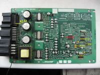
I often search forums for information on the repair of various devices. I am very annoyed by the fact that the producers do not provide (even for a fee) service manuals. And they wish for exorbitant sums for repairs or force them to buy new devices. Therefore, I decided to share information on the pages of this forum about my fight with a damaged Bose GS1E 66 920A car amplifier. from the Mazda 6.
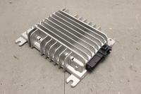
I hope that this information will help others to repair themselves and save a lot of money (a new amplifier in Mazda costs about 6kPLN)
The story begins when one day when I started the car I heard a loud crack in the loudspeakers (the sound you get when you turn on bad amplifiers without a speaker protection system) As a moment earlier there was a storm, I thought that the car must have accumulated some electrostatic charge and it probably was cause. After that one click, the radio started to play normally. In the following days, similar crackles began to appear randomly while driving (not when starting the car). Interestingly, these crackles started to appear more and more often until one day after starting the car, instead of playing, the amplifier started to generate a loud rattling noise on all the speakers. The sound sounded like someone was feeding a square wave signal to the amplifier input. Restarting the amplifier did not help.
Added after 1 [hours] 6 [minutes]:
After dismantling the casing, we can see such a layout
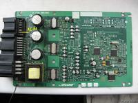
To begin with, I decided to identify the main components of the amplifier to understand what the author meant It was not easy, but it looks like this in the end
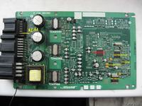
Then it was time to connect the amplifier outside the car, I managed to find SEVERAL VERSIONS of the diagram, so I was forced to draw my own after checking if it was the same for me
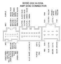
I gave the voltage to + 12V, ground and additionally + 12V to the REMOTE ON terminal
More discoveries in the next message
Added after 28 [minutes]:
The amplifier has a DSP processor that corrects the acoustics of the car. The signal from the amplifier inputs is sent to the A / D converters in the CS42438 circuit, then in digital form to the DSP processor, from where it returns to the CS42438 from it to the power amplifiers and then to the loudspeakers. As it is unlikely that all six channels (power amplifiers) were damaged at the same time, my first suspicion fell on the power circuits.
I checked whether the voltages at the stabilizer outputs are correct, as shown in Fig.
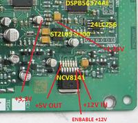
On pin 1 of the NCV8141 chip + 12V appears (power to the amplifier), the second output is the stabilizer (turning the key in the car gives the voltage to this foot, the so-called REMOTE ON), on foot 7 we have + 5V output. This voltage supplies the A / CC / A converters and the second ST2L05-3300 stabilizer which produces two voltages + 3.3V for Converters and DSP, and the second voltage + 1.25V supplying the DSP core.
It turned out that all voltages are correct and are applied to the appropriate pins of the converter and DSP as described in the manufacturer's documentation
Added after 4 [hours] 45 [minutes]:
The amplifier connected to the table took about 0.7A from the power supply, none of the stabilizers got hotter in the A / D converter, DSP and serial memory were also cold. The power amplifiers, on the other hand, sounded light.
After checking the correctness, powered on all integrated circuits, I thought that maybe the problem is that the power amplifiers send a diagnostic signal to the processor which stops work. From the data of the TDA circuits, I read that they can be controlled by I2C. Unfortunately, after checking the system configuration in the amplifier, it turned out that these systems work independently and do not use I2C.
I decided to connect the audio signal to one of the inputs and check what was happening
The signal reached the inputs of the A / D converter and that's it. Searching for signals on individual pins of the converter allowed to discover an interesting thing - regular reset pulses appear on the reset leg. There was an idea that maybe the A / D converter is damaged and the processor is trying to reset it. I found such a converter in a drawer quite by accident and replaced it. Unfortunately, that didn't help either.
Further research revealed that the reset pulses were also applied to the DSP, which meant that it was not the DSP that generated the reset.
I returned to the datasheets again and it turned out that the source of the reset signal is a + 5V stabilizer which is equipped with a watchdog input and must receive pulses of the appropriate frequency from the processor and if it does not get them, it generates a reset signal.
I checked with an oscilloscope that the DSP does not actually communicate with other parts of the system. The only floating signals appear on the oscillator pins and in the clock reset pulse on the serial memory pins.
and so I came to the conclusion that the problem is in the DSP.
Unfortunately, checking this theory must wait until the ordered processors arrive :)
So that the story will have to wait for its ending

I hope that this information will help others to repair themselves and save a lot of money (a new amplifier in Mazda costs about 6kPLN)
The story begins when one day when I started the car I heard a loud crack in the loudspeakers (the sound you get when you turn on bad amplifiers without a speaker protection system) As a moment earlier there was a storm, I thought that the car must have accumulated some electrostatic charge and it probably was cause. After that one click, the radio started to play normally. In the following days, similar crackles began to appear randomly while driving (not when starting the car). Interestingly, these crackles started to appear more and more often until one day after starting the car, instead of playing, the amplifier started to generate a loud rattling noise on all the speakers. The sound sounded like someone was feeding a square wave signal to the amplifier input. Restarting the amplifier did not help.
Added after 1 [hours] 6 [minutes]:
After dismantling the casing, we can see such a layout

To begin with, I decided to identify the main components of the amplifier to understand what the author meant

Then it was time to connect the amplifier outside the car, I managed to find SEVERAL VERSIONS of the diagram, so I was forced to draw my own after checking if it was the same for me

I gave the voltage to + 12V, ground and additionally + 12V to the REMOTE ON terminal
More discoveries in the next message
Added after 28 [minutes]:
The amplifier has a DSP processor that corrects the acoustics of the car. The signal from the amplifier inputs is sent to the A / D converters in the CS42438 circuit, then in digital form to the DSP processor, from where it returns to the CS42438 from it to the power amplifiers and then to the loudspeakers. As it is unlikely that all six channels (power amplifiers) were damaged at the same time, my first suspicion fell on the power circuits.
I checked whether the voltages at the stabilizer outputs are correct, as shown in Fig.

On pin 1 of the NCV8141 chip + 12V appears (power to the amplifier), the second output is the stabilizer (turning the key in the car gives the voltage to this foot, the so-called REMOTE ON), on foot 7 we have + 5V output. This voltage supplies the A / CC / A converters and the second ST2L05-3300 stabilizer which produces two voltages + 3.3V for Converters and DSP, and the second voltage + 1.25V supplying the DSP core.
It turned out that all voltages are correct and are applied to the appropriate pins of the converter and DSP as described in the manufacturer's documentation
Added after 4 [hours] 45 [minutes]:
The amplifier connected to the table took about 0.7A from the power supply, none of the stabilizers got hotter in the A / D converter, DSP and serial memory were also cold. The power amplifiers, on the other hand, sounded light.
After checking the correctness, powered on all integrated circuits, I thought that maybe the problem is that the power amplifiers send a diagnostic signal to the processor which stops work. From the data of the TDA circuits, I read that they can be controlled by I2C. Unfortunately, after checking the system configuration in the amplifier, it turned out that these systems work independently and do not use I2C.
I decided to connect the audio signal to one of the inputs and check what was happening
The signal reached the inputs of the A / D converter and that's it. Searching for signals on individual pins of the converter allowed to discover an interesting thing - regular reset pulses appear on the reset leg. There was an idea that maybe the A / D converter is damaged and the processor is trying to reset it. I found such a converter in a drawer quite by accident and replaced it. Unfortunately, that didn't help either.
Further research revealed that the reset pulses were also applied to the DSP, which meant that it was not the DSP that generated the reset.
I returned to the datasheets again and it turned out that the source of the reset signal is a + 5V stabilizer which is equipped with a watchdog input and must receive pulses of the appropriate frequency from the processor and if it does not get them, it generates a reset signal.
I checked with an oscilloscope that the DSP does not actually communicate with other parts of the system. The only floating signals appear on the oscillator pins and in the clock reset pulse on the serial memory pins.
and so I came to the conclusion that the problem is in the DSP.
Unfortunately, checking this theory must wait until the ordered processors arrive :)
So that the story will have to wait for its ending


