logo elektroda
logo elektroda
X
logo elektroda

Simple Adjustable Low-Pass Filter: 12V/5V Power, Dual 50k Potentiometer - Diagrams Needed

HappyWhite 5475 10
ADVERTISEMENT
Treść została przetłumaczona polish » english Zobacz oryginalną wersję tematu
  • #1 16225999
    HappyWhite
    Level 7  
    Will anyone help with the construction of a low-pass filter?
    I would like something quite simple, powered by 12V or 5V and of course to be adjustable (dual 50k potentiometer). If someone knows more, please send me some diagrams.
    Thanks in advance :)
  • ADVERTISEMENT
  • #3 16226195
    Freddy
    Level 43  
    HappyWhite wrote:
    Will someone help with the construction of a low-pass filter?
    What is this filter for?
  • ADVERTISEMENT
  • #5 16227031
    HappyWhite
    Level 7  
    _lazor_ on the passive filter supposedly there are big losses ... That's why I want some active solution.

    I have two questions for you ...

    1. Is there any sense in giving a low pass filter to the input of an amplifier that "goes" to the woofer and a high pass filter to the input of an amplifier that "goes" to the midrange drivers (3). The entire speaker will be based on 3x PAM8610. Two mid-range speakers will be connected to one amplifier, 3 the same mid-range speakers to the second amplifier ... and the woofer to the third.

    2. If it makes sense, should I provide a high-pass or medium-pass filter to the midrange speakers?
  • #6 16227300
    aksakal
    Tube devices specialist
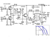
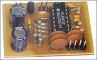
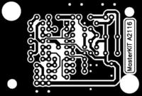
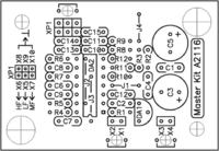
    It may make sense to use filters for separate three power tips. If you are interested in the diagram, I will put out the nominal values of the elements and PCBs. Simple Adjustable Low-Pass Filter: 12V/5V Power, Dual 50k Potentiometer - Diagrams Needed
  • ADVERTISEMENT
  • #7 16227348
    HappyWhite
    Level 7  
    Emmm sorry but I'm a beginner ... :) maybe something on one operational amplifier? Of course, I mean one operational amplifier for 1 filter And how can you send some good operational amplifiers for 5v to 12v for this purpose because nwm of how many volts I will still supply

    And if you are experienced in this, it is like sending me a list of elements
  • #8 16227351
    jarek_lnx
    Level 43  
    There are two requirements, the first is not to lead to the loudspeaker signals that can damage it, the second - more important for the listeners, how to connect the bands of different speakers so that they work together, the bands must connect so that there is no "hole" or "hill" and that the phase in the transition zone, it matched.

    In the sixties, two experts, Russ Riley and Siegfried Linkwitz, thoroughly analyzed the subject, so if you don't want to do crap, look for "Linkwitz-Riley Crossovers" filters (3-way)
    e.g
    link
  • #9 16227395
    aksakal
    Tube devices specialist
    Dear colleague! The amplifiers indicated in the diagram are located in 1 housing. Simple Adjustable Low-Pass Filter: 12V/5V Power, Dual 50k Potentiometer - Diagrams Needed
  • ADVERTISEMENT
  • #10 16227399
    HappyWhite
    Level 7  
    Buddy, I point out again that I am a beginner ... Please give me something simple :D On one operational amplifier, I would like it, and generally with little need for discrete components.
    Once again ... I am asking for some very simple but active filter for bass and sound (i.e. low-pass and high-pass)
    And nobody answered me ... Can I connect the midrange speaker to the low-cut filter?
    Added after 1 [minutes]:
    Will you send the back of the tile?

    Can I make such a filter on a prototype board and use a "spider" from the bottom instead of paths? It often happens to me that while leading tin paths, the pads fall off.

    And if you could create a wiring diagram for me in Eagle or other, but not as individual amplifiers, only the circuit diagram.
    Integrated circuit, resistors, encoders
  • #11 16227421
    aksakal
    Tube devices specialist
    Colleague, jarek_lnx! Yes, I am to the author of the topic and I recommend an analogous scheme, just simpler, taking into account what my colleague - a beginner.

    Added after 3 [minutes]:

    It's easier for the fact that I put out, there can only be passive filters.

    Added after 4 [minutes]:

    Simple Adjustable Low-Pass Filter: 12V/5V Power, Dual 50k Potentiometer - Diagrams Needed Simple Adjustable Low-Pass Filter: 12V/5V Power, Dual 50k Potentiometer - Diagrams Needed

Topic summary

The discussion revolves around constructing a simple adjustable low-pass filter powered by either 12V or 5V, utilizing a dual 50k potentiometer. Initial suggestions include using a passive RC filter, which can be adjusted with a potentiometer, but concerns about signal loss lead to a preference for an active solution. The user seeks guidance on implementing filters for a speaker system involving three PAM8610 amplifiers, specifically asking about the appropriateness of low-pass and high-pass filters for different speaker types. Several users recommend researching Linkwitz-Riley crossovers for optimal speaker integration and provide links to diagrams. The user expresses a desire for a straightforward design using a single operational amplifier and minimal discrete components, requesting a wiring diagram and advice on using a prototype board.
Summary generated by the language model.
ADVERTISEMENT