logo elektroda
logo elektroda
X
logo elektroda
ADVERTISEMENT
Treść została przetłumaczona polish » english Zobacz oryginalną wersję tematu
📢 Listen (AI):
  • Dear Forum Members,
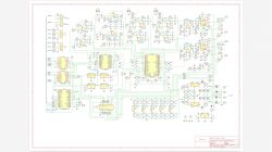
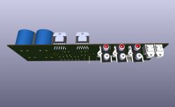
    I have decided to make something for myself. As I'm not happy with the market offerings (reasonably priced and accessible to me) of devices called streaming players, I decided to make something that would satisfy me. The basic premise was to design an audio track - reasonably good, but no fiddling - with a DAC added. This took the form of a single board. A controller (Cortex-M0) with a display is still to be made, topped off with a Raspberry Pi as a digital audio service centre (probably also with a display). Optionally, I may add some kind of UKF tuner with digital output to the set.
    The attached files show the current state of the project and here I ask for everyone's feedback. It's well known that one pair of eyes often won't spot a mistake, and I'm hoping that maybe someone will see what I've missed.
    Regards

    Visualization of a PCB with audio components Close-up of a designed electronic circuit board with various components, including capacitors and red elements. Audio circuit schematic with a DAC and electronic components. .

    Cool? Ranking DIY
    About Author
    Cezary_
    Level 18  
    Offline 
    Cezary_ wrote 242 posts with rating 57, helped 16 times. Been with us since 2003 year.
  • ADVERTISEMENT
  • #2 21220029
    hetm4n
    Level 20  
    On the raspberry a ready-made system will you use? Or something of your own?
  • ADVERTISEMENT
  • #3 21220060
    Cezary_
    Level 18  
    >>21220029 .
    Probably standard raspios. Quite a few libraries will be needed, so support is important. A few applications will need to be written, a remote desktop for these games will be useful. I don't know yet whether an RPi Zero or a large one will suffice. If not using a desktop (Raspberry Pi OS Lite), the Zero would probably be fine. But all this remains to be seen. Fortunately I have strong personal support for this at home.
  • #4 21220086
    dktr
    Level 25  
    As an FM tuner I strongly recommend the TEF6686 or the better TEF6687. You can test how it works with the right antenna.
  • #5 21220097
    Cezary_
    Level 18  
    >>21220086 .
    I was tentatively considering the Silabs Si4743, but will look at what you suggest. Thanks.
  • #6 21220710
    pikarel
    Level 38  
    If you can, change the position of audio power circuits and sockets - to the other side of the PCB; then you will have the components on one side, thus the PCB assembly in the enclosure will be simpler, and the enclosure itself will be lower.
    Such an arrangement as in the graphic is rarely used in this type of construction.
    If you change this, I am willing to make it myself, according to your design :) .

    Have a look at what the boards of SAT decoders or car receivers look like with a 1DIN panel.
  • ADVERTISEMENT
  • #7 21220784
    Cezary_
    Level 18  
    I have made this arrangement deliberately. The connectors are planned on the rear wall of the case, of course, and above them, from the surface of the board upwards, I want to mount an outward projecting SK42/50/SA heatsink (5 cm high) from a Polish shipping company. The whole chassis will then be up to 9 cm high and this will be a good dimension for some sort of front panel display.
    If you have a different idea for the mounting, you will make adjustments to the design. I will publish the files here once the final version is agreed.
  • #8 21221072
    gulson
    System Administrator
    Thank you for sharing the whole project! That's very kind of you. There are indeed quite a few modules, but looking for one, I wasn't quite satisfied either.
    If you drop me a PM, I'll send a small gift, it will come in handy for the raspberry ;) .
  • #9 21222061
    Cezary_
    Level 18  
    @gulson,
    unfortunately this is not the whole project yet, there will be at least one more album. The draft of the first disc, after the last corrections, flew the net (along with the corresponding amount) to the Far East to be made. Once it has been edited, checked and any corrections made, I will publish it in full.
    Thanks for the good word and the gift.
  • #10 21223254
    katakrowa
    Level 23  
    I really like the layout although for now you have a stereo power amplifier with three analogue inputs, two digital inputs and digital volume control - unfortunately no control panel yet.
    As a project in the picture it looks cool. Will it play well... You'll see when you solder it up. I wish you that it will play satisfactorily the first time, but I guess there is still a lot of work to do before that happens.
    Very interesting circuit by the way: NJW1194 - it's tempting to buy it as it has nice parameters especially bass and treble control in +/- 10dB ranges.

    You use a lot of circuits with very low noise levels, but the LM3886 will not reflect this "work" because its SNR is ~92dB. There's no harm in going "overboard", but I don't know if all those power supply sections and that many stabilisers will make any positive difference. I would simplify it.

    2) Maybe it's just a matter of description on the schematic, but from 22V AC you won't get +/- 35V DC but about 31V (that's about 10% difference). So, if you have calculated the resistors at the LM317, you may have slightly lower voltages than expected and this may result in somewhere in the audio circuit, the signal may overdrive at a lower level than you expect. Problems can occur at quite high signals, but before the LM3886 itself, you no longer have the possibility of adjusting, because everything is soldered on resistors.

    3) I also don't know how robust the 5V power supply circuit will be on the Zener diode and stabiliser because I can't see what you are powering from it.

    Cezary_ wrote:
    The design of the first board, after final adjustments, flew the net (along with the relevant amount) to the Far East for completion. Once it has been edited, checked and any corrections made, I will publish it in full.


    I am very curious to see what you come up with. I would very much like you to run it through at least RMAA at the end and show the results. If the whole thing will actually have that SNR at the level of the LM3886 then I think the circuit is worthy of consideration.

    Although it's a pity that you didn't implement any uC on it to make the board 100% independent, e.g. controlled via UART.
    After all, apart from volume control, balance, and input selection, you can't control anything else from the outside anyway, and so the burden and necessity of understanding how the device works is transferred to a separate module/circuit. Secondly, instead of 3 cables you will need 20.
    UART control also has the advantage that by the time you make this second controller, you could already use the presented device via a console from your computer and with the "default" settings it could already be a full-fledged power amplifier.
    Additionally, referring to the topic, this would be the first "network" function of this set. So far there is not much of a network here - well, maybe apart from the network of cables to the controller :-) .
    But that's a matter of taste...

    Overall nice design.
  • #11 21223306
    Cezary_
    Level 18  
    >>21223254 .
    Thanks for your kind summary.
    You're very right in your comments, but with constructions like this that are singular and not based on previous experience, it's difficult to make precise assumptions on the first attempt. It is a bit like that, that the subsequent elements of the whole come into being later, and so it is in this case. Here, I confess that I had already assembled a complete stereo power amplifier on LM3886 with power supply and servo circuit (and as many as 5 pieces that I had put aside...), after which I changed my mind a bit and what you see came out.
    As for the components, I tried for as good as possible and they may be a bit over the top, but their cost was low enough that there was no point in giving something inferior (e.g. OPA1678s at about £3 each). Similarly, metallized resistors - about 15 gr. a piece. The number of stabilisers is based on various audiophile (but not only) considerations I have read. I don't have any experience with audio DAC circuits and I also had doubts whether I needed that many, but what the heck - 4 circuits in small SOT23 cases for a zloty apiece - I can go wild.
    Professionally, I do projects for production in "slightly" larger quantities than 5 pieces for the family and then no excess component is welcome. But in this case, as this is practically a prototype with no previous history, it could probably be simplified in the next step.
    The power transformer is an Indel TST 160/073, which gives 2x22 V at full load (in which case the voltage after the bridge is just over 30 V). With no load there is about 35 V on the mains filter capacitors. The description itself is perhaps a little misleading.
    From the LM317/LM337 stabilisers I want to get about 7.5 V and there the resistors R92 and R95 are a little too small (they should be 91 Ω). The current consumption from both voltages will not exceed 100 mA, so the voltage drops on R105 and R106 will be below 10 V, so there should be plenty of headroom (above 10 V per stabiliser). The peak value of the audio signals at the U15 outputs is expected to be about 2.4 V, so a symmetrical supply of 7.5 V gives an adequate reserve. I assume the sensitivity of the AUS1/AUX2 inputs to be 0.7 Vrms (nominally), for such a signal there will be 2.4 Vpeak at the U15 inputs. This gives about three times the headroom for overdrive. What I don't know, and this I will determine experimentally, is whether R32 and R37 are adequate for getting the correct level of signal from the turntable. If I am making a mistake here, please guide me.
    For the commissioning stage of this board, I plan to use a simple interface with a 74HC595 shift register, which will have input control (clock, data and strobe) from the PC side via a simple RS232 (with appropriate simple voltage value conditioning), and I will attach the parallel outputs of this register to the P12 connector. A suitable program with faders and selection controls is already "being written". I plan to place the target controller at the front of the enclosure, as it will also have a display, a knob with pulse output and some buttons to operate. The connection of the controller to the audio board will be handled by a simple 20-pole ribbon.
    And the network functions will be handled by the RPi, communicating with the controller. These are the assumptions, their implementation will take place in the next steps. And how it will turn out - we will see. It's a bit of a game in the dark, because it's supposed to be fun too.
    Thanks for your comments (and please give me more).
  • ADVERTISEMENT
  • #12 21223324
    nyquist
    Level 26  
    Interesting project.
    A question out of curiosity - why have resistors R93, R96 been included between the outputs of stabilisers U20, U21 and filter capacitors C97, C99? Do they not negatively affect the stability of the stabilisers' operation?
  • #13 21223410
    Cezary_
    Level 18  
    >>21223324 .
    The data sheets for the LM337 and LM317 state to use an electrolytic or tantalum capacitor at the output, and such have ESRs of 100 milliohms or more. I inserted MLCC capacitors there with a negligible ESR, which could potentially lead to instability. Hence the two resistors, I will practically select them and check how the whole thing behaves.
  • #14 21230678
    pikarel
    Level 38  
    Cezary_ wrote:
    >>21223324 .
    The data sheets for the LM337 and LM317 state to use an electrolytic or tantalum capacitor at the output, and such have ESRs of 100 milliohms or more. I inserted there MLCC capacitors with a negligible ESR, which could potentially lead to instability. Hence the two resistors, I will practically select them and check how the whole thing behaves.
    .
    Where do you get such information from?
    A resistor is used if the charging current to the capacitor is likely to be destructive, in practice these are systems fed directly from the mains and the capacitor is after the rectifier.

    The capacitor by its negligible series resistance acts as a short pulse filter, and you are adding a resistor in series.
    A strange understanding of its function in the circuit.
  • #15 21231380
    Cezary_
    Level 18  
    Quote:
    Where do you get such information from?

    manufacturer analyses (and more) suggest such a solution, e.g.:
    https://www.ti.com/lit/an/snva167a/snva167a.pdf
    https://www.ti.com/lit/an/slva115a/slva115a.pdf?ts=1726650016478
    https://electronics.stackexchange.com/questio...ing-capacitors-for-a-linear-voltage-regulator
    Quote:
    A resistor is used if the charging current to the capacitor is likely to be destructive, in practice these are circuits fed directly from the mains and the capacitor is after the rectifier.

    Yes, but here we are dealing with a different phenomenon: a problem with the stability of the circuit with feedback.
    Quote:
    The capacitor by its negligible series resistance acts as a short pulse filter, and you are adding a resistor in series.
    Strange understanding of its function in the circuit.
    .
    Of course, you are right - the higher the capacitance and the lower the series resistance, the better the response to a step change in load current. In my circuit, in principle, this parameter will not deteriorate, because the output of the stabilised voltage is derived directly from the capacitor terminals (here C97 or C99), and the resistor (R93 and R95) is included where it will possibly slightly degrade the voltage stabilisation - for expected loads from zero to 100 mA by 33 mV at most.
    Thanks for your comments, if you have any more I'd love to hear from you.
  • #16 21231506
    pikarel
    Level 38  
    To plant baboos in TI documentation? (second link).
    In the second figure (Figure2) the ESR unit is µF :) .

    Besides; it is clear from the description that the low ESR problem only affects old LDO designs (with Ultra-Low IQ), with low output voltages (0.8V - 2V).
    You are using LM317 and voltages in the 15-30V range.

    And the third link - that's even a waste of time to read.
  • #17 21231577
    Cezary_
    Level 18  
    >>21231506 .
    The LM317 and LM337 circuits are from a time when large MLCC capacitances were not used (as can be seen in the data sheet in the description of the output capacitors). I prefer to take precautions, as I have not tested the test circuit. This whole project is just a test. I can always change the value of these resistors to zero if they prove unnecessary. Life is full of surprises...
  • #18 21231865
    pikarel
    Level 38  
    These dilemmas with 0.1Ω and quibbles about the coupling loop in the stabiliser date back to the days when MSI digital circuits required a 100nF capacitor at each cube. At that time, with just 10 such capacitors, the resultant ESR was already decreasing to negligible values and the resultant capacitance was increasing by an order, up to µF, hence the problems.
    At that time, it was even mandatory to place 100nF at the leads of the stabiliser and the rest of the capacitors directly at the leads of the digital cubes. Additional resistance was created from tracks on the board or an inductor was used in the power supply line.
    The allowable power supply variation at 5V was 5%, giving a large margin of 0.25V.
    With a low supply, e.g. 1.25V - 5% is 60mV, so these oscillation values are what the manufacturer fights for, because circuits supplied with such 'ringing' simply reset.

    Nowadays, coils are an everyday occurrence because the ubiquitous 'digital' is an everyday occurrence.
    It is enough to look through the schematics of modern devices for the power supply lines.
    You won't see series resistors, but coils are "in abundance", both in the inverters themselves and before and after them.
  • #19 21232951
    sq3evp
    Level 37  
    Interesting project - control from smartphone will be too?
    Description of the project interesting - could be an inspiration for someone else.
  • #20 21256180
    Cezary_
    Level 18  
    I can write with satisfaction that the thing has moved and is playing!
    Prototype interface board with electronic components for audio amplifier .
    In the photo you can see how it came out. You can also see the makeshift aluminium channel heat sink, the TST160/073 transformer and the prototype interface board (more on that later).
    I haven't checked everything thoroughly - I'm still missing the metallized 22k and 220 resistors that are supposed to go into the RIAA equalizer amplifier. The rest looks to be in working order.
    The boards were made by PCBWay, a Far Eastern company advertised on Elektroda. I have specified a 70 µm (2 oz) copper layer in the parameters, and this is to keep the resistance in the power circuits as low as possible. To this end, the paths of the ground and both power lines are partially uncovered with a mask (you can see this on the PCB design). I thickened the ground line by soldering a copper wire fi 0.7 mm. I have not thickened the power supply lines for the time being. Whether these measures are necessary could be determined by measuring several copies made differently, which for obvious reasons I am unlikely to do.
    Assembly was no more difficult than for similar circuits, except perhaps for capacitors C75..C78 and C86..C88. Probably they could have been placed slightly differently to make hand soldering easier. I also didn't give them fields with "thermal" connections, because I didn't want to reduce the effective cross-section of the tracks and this would have made assembly more difficult.
    Because of the noise, I aimed for all resistors in the audio circuit to be of the metal-film type; as a result, due to lack of availability, some of them have a slightly different value than in the original schematic. These changes are included in the project documentation. I will have to wait a little longer for the 22k and 220k resistors. Similarly, I have not been able to purchase some capacitors with a sufficiently small tolerance (2%) and for the time being, five percent capacitors are used.
    The gain adjustment range of the U15 is between -95 dB and +31.5 dB. The entire circuit is calculated so that the amplifier's full power should be achieved when the AUX inputs are driven at 0.7 V. The DAC has a nominal output signal value of 2 V and this too is supposed to be sufficient for full drive. However, often the signals have non-standard lower values and it is worthwhile that the maximum gain could be higher. I'm yet to work this out exactly, but surely the volume control should be able to be set above the 0 dB level - I'm guessing within +6..+10 dB. This will be easy to set in the software controlling the NJW1194 chip. I will determine the gain for the PHONO input (R32 and R37) when I have access to such a rare device called a turntable.
    I checked the digital part using the TV's TOSLINK signal through both inputs. I didn't check the I2S1 and I2S2 inputs, well if everything works with the DIR9001, then the straight inputs shouldn't whimper either. It was necessary to put a JP2 jumper. To be honest, I still don't know how it should be configured.
    Commissioning would be unfeasible without the ability to send settings (volume, tone, input selector) to U15. To achieve this, I made a simple interface to the computer, using the most readily available peripheral - a USB-RS232 adapter. This required assembling a small prototype board and "tapping" a piece of software. Schematic of the interface below, I will make the program available if anyone is interested.
    RS232 interface schematic for computer-controlled audio system. .
    A preliminary check of the frequency response showed that the -3dB frequency response is between about 30 Hz and 70 kHz. Such a high lower frequency is, so to speak, intentional; it came out similarly in simulation. Lowering the lower limit requires increasing the capacitance of the coupling capacitors (470 nF single and paired, especially those at the U15 inputs and C70, C71, C80, C81). In my opinion, however, this is not a problem, I do not have speakers capable of processing such low frequencies, so per balance it is a beneficial solution.
    The audible noise, in my opinion, is at a low level, nor is it audible (and not visible on the oscilloscope) that there is anything disturbing happening in the area of distortion and possible excitation. There will be time for precise measurements once the whole is assembled.
    Stabilisers U20 and U21 get very warm during operation, as expected (loss power of about 1.5 W), but not so much that they need to add heatsinks. The +5 V supply for the digital part, which I had planned to feed from a second power supply, is also made on this board (U23), and this is to facilitate start-up and testing. Because of the losses, it's not a very happy solution, but diode D95 will cut the load on U23 if there is external power on the CN13 connector.
    My conclusions at the moment: presumably the capacitance values attached to leads 6 and 27 of the NJW1194 (gain control boost circuit) can be significantly reduced, provided the maximum value of +31.5 dB is not used. If I limit the gain to 10 dB, the 'potentiometer' part of the IC connected to ground will be of such a high value that using smaller capacitances C60-61 and C62-63 will not significantly raise the lower limit of the frequency response. I believe that limiting the gain to a maximum value of 0 dB makes it possible to dispense with these capacitances altogether. I also did a quick test by short-circuiting terminals 6 and 27 to ground, but a slight 'knock' was then heard when adjusting the gain. You can see that it is necessary to cut off the DC to make the regulation work quietly. The same is true of the capacitors connected to terminals 16 and 17, namely C68 and C69. And here smaller values would probably suffice. If I check this at some point, I will give exact conclusions.
    In the final amplifier, the servo circuit (U16, C71, R74, C81, R84) behaves very well. The DC component at the loudspeaker outputs is in the single millivolts and no instability can be seen when driven. The big plus of this solution is that there is no need for a large capacitance in the LM3886 feedback. Worse - an electrolytic capacitor is often used here, which can definitely have a bad effect on distortion levels. I recommend the online article 'Selecting Capacitors to Minimise Distortion in Audio Applications', by Zak Kaye of Texas Instruments.
    Now it's time to do the design of the STM32 controller with display, the power supply for the digital part. including RB-Pi.

    @sq3evp
    Will there be smartphone control? There will be many different things, plans are extensive. The board on display is intended to be an audio hardware base for the Raspberry Pi, with everything the heart desires included.
  • #21 21256268
    sq3evp
    Level 37  
    Cezary_ wrote:
    .
    @sq3evp
    Will there be control from a smartphone? There will be many different things, plans are extensive. The board on display is intended to be an audio hardware base for the Raspberry Pi, incorporating everything the heart desires.

    I am liking the project more and more.
  • #22 21282120
    katakrowa
    Level 23  
    Cezary_ wrote:
    .
    Because of the noise, I aimed for all resistors in the audio path to be of the metallized type(...)

    A preliminary check of the frequency response showed that the -3dB frequency response is between about 30 Hz and 70 kHz. Such a high lower frequency is, so to speak, intentional; it came out similarly in the simulation. (...)

    The audible noise is, in my opinion, at a low level, nor is it audible (and not visible on the oscilloscope) that there is anything disturbing happening in the area of distortion and possible excitation. There will be time for exact measurements once the whole thing is assembled.


    The easiest way is to install the RMAA and take measurements - then we will see everything as it actually is. Because you know "by ear" you can hear different things or not hear and you can tell anything :-) and actually I am curious about the final result.
📢 Listen (AI):

Topic summary

The discussion centers on a custom-designed audio kit integrating network functions, featuring a single-board audio track with an added DAC and a Raspberry Pi serving as a digital audio service center. The Raspberry Pi is planned to run standard Raspberry Pi OS with necessary libraries and applications, with consideration between using a Raspberry Pi Zero or a larger model. An optional UKF/FM tuner with digital output is contemplated, with recommendations for TEF6686 or TEF6687 tuners over the initially considered Silabs Si4743. The PCB layout includes a deliberate arrangement of audio power circuits and connectors to accommodate a heatsink and front panel display, differing from typical designs. The power amplifier uses an LM3886 with multiple analog and digital inputs and digital volume control, supported by low-noise components such as OPA1678 operational amplifiers and NJW1194 tone control IC. The power supply design includes multiple stabilizers (LM317, LM337) with output capacitors and series resistors to ensure stability despite the use of low-ESR MLCC capacitors, a point of technical debate referencing manufacturer application notes. The project is in progress with PCBs fabricated by PCBWay, featuring thick copper layers and reinforced ground lines to reduce resistance. The author plans further refinements including metallized resistors in the RIAA equalizer stage. Testing and measurement suggestions include using RMAA software to objectively assess audio performance. The project aims to provide a reasonably priced, accessible, and high-quality streaming audio solution with potential smartphone control and modular expansion.
Summary generated by the language model.
ADVERTISEMENT