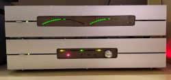
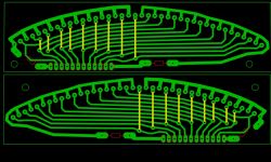
Elektroda.com
Elektroda.com
X
This content has been translated flag-pl » flag-en View the original version here.
  • About Author
    pepepe1
    Level 12  
    Offline 
    pepepe1 wrote 64 posts with rating 114. Been with us since 2003 year.
  • #2
    James596
    Level 23  
    As for me, it works a bit too "nervously", although it's a matter of taste as you like. :)
  • #3
    CHOPIN66
    Level 14  
    It looks cool, but for me it's an excess of form over content - why push atmega for this purpose? Such an indicator can be implemented on the LM3916 and the Peak meter indicator can also be easily done - 4 transistors working in a peak detector + an operational amplifier performing the logarithm function and the LEDs are controlled as in the WS442 using transistors connected in cascade. Take a look at the diagram of the AIWA AD 6900 tape recorder. The peak meter indicator is made as I described - instead of LEDs there is a VU meter, and we also have a sample and hold function. And it's all analog, no uC.
  • #4
    bsw
    Level 20  
    I will say more, why use diodes, when you could put classic V-gauges.
    Probably "to be pulled out" cheaper than the new atmega now.
    BTW:
    Cleverly made front panels.
  • #5
    Galareta
    Level 23  
    Especially since this LM will be more expensive. Just use Padauk's uC or some new tinny series and LM will be more expensive.
    That's why I have a uC to use them.

    The new tiny costs ~ PLN 3, the new pdk costs PLN 0.40.
    I recently bought the STM32G030 for PLN 6 with some pennies - and this is power. Only the outdated atmega8/32 chips are expensive, but that will probably change soon as well.
  • #6
    pepepe1
    Level 12  
    The uC was the easiest to use electrically, and the module was supposed to match the aesthetic concept (preamplifier visible underneath, second power amplifier and tuner). Swing-out with such a large rectangular dial simply wouldn't fit. I omit whether they are available for purchase, for how much, and that I have no influence on the appearance of the dial when purchased. This is just an indicator, there is no requirement of accuracy like in a tape recorder, where you have to be careful not to distort the recording.
  • #7
    bsw
    Level 20  
    pepepe1 wrote:
    Swing-out with such a large rectangular dial simply wouldn't fit. I omit whether they are available for purchase, for how much, and that I have no influence on the appearance of the dial when purchased.

    It was a joke with the tilting one - of course they wouldn't fit in the housing.

    However, I would make flat rulers, not arched and one under the other or divergent, and windows in housings of the same size.
  • #8
    djfarad02
    Level 19  
    CHOPIN66 wrote:
    It looks cool, but for me it's an excess of form over content - why push atmega for this purpose? Such an indicator can be implemented on the LM3916 and the Peak meter indicator can also be easily done - 4 transistors working in a peak detector + an operational amplifier performing the logarithm function and the LEDs are controlled as in the WS442 using transistors connected in cascade. Take a look at the diagram of the AIWA AD 6900 tape recorder. The peak meter indicator is made as I described - instead of LEDs there is a VU meter, and we also have a sample and hold function. And it's all analog, no uC.


    Doing something like this in analog is a complete misunderstanding, not these times. Why complicate the design, increase the cost, limit the possibility of modifications?
  • #9
    tytka
    Level 21  
    And I completely do not understand placing such trinkets in such a form in an amplifier.
    If it was calibrated and indicated the power output, I would understand. But without that, what's it for? Just to flash? I don't understand. Is it completely useless? And I think you can see it yourself:

    pepepe1 wrote:
    This is just an indicator, there is no requirement for accuracy like in a tape recorder

    Besides, what are we supposed to evaluate here? You presented some drawing of the board and a video of the operation. You didn't even show how you physically did it.
    And let me disagree with these words:

    pepepe1 wrote:
    I have no influence on the appearance of the dial in the purchased ones

    The shield can be changed. You obviously haven't seen the wonders people can do with it.
  • #10
    pepepe1
    Level 12  
    Whatever, whatever.

    You can scale (there are PRs), scale can also be applied, but why? It is supposed to blink, just like the VU-meter on the 2*20 LCD described on Elektroda or the Chinese rulers. The Dior WS-432 also had an LED indicator, which no one used to adjust the volume - it was a gimmick, an ornament, an aesthetic element.
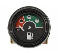
    At one point I needed a pointer for the faceplate, and nothing was ready. Whoever wants to can easily copy it. I shared the effect of my shorter or longer work. If I wanted to brag about it, I would probably go to Insta :)
  • #11
    tytka
    Level 21  
    pepepe1 wrote:
    scale can also be applied, but why?

    For it to make sense. I don't like pointless trinkets in the equipment, for me it's just "wiocha". Personally, I'd prefer a plain/bare front-panel to such flashing trinkets, Just just for the flash.

    pepepe1 wrote:
    The Dior WS-432 also had an indicator on the LEDs, which no one used to adjust the volume

    Do not compare it to your solution, because the mentioned amplifier had scaled indicators so that they showed (indicatively) the output power. So they made sense there.
  • #12
    pepepe1
    Level 12  
    tytka wrote:
    So they made sense there.

    If anyone likes looks... :lol:
  • #13
    tytka
    Level 21  
    With all due respect, you're the lover of appearances here.
    You named your creation "Vehicle Indicator" (for the amplifier). And what is the boost indicator??? For it to be called a VU indicator, it would have to have a scale and indicate a specific value. And you have not even (so far) boasted about what signal, where it was taken from, you feed to the inputs of these trinkets and how these indications relate to the value of this signal. So I'm asking, what is the VU indicator? Control what? I think it would be better to change the title to one of these:
    - LED linear trinkets for the amplifier,
    - The diode line simulated on the VU indicator.

    P.S
    Not that I just want to criticize.
    I really like the use of a microcontroller to build a signal indicator. I once developed a certain indicator implemented on a microcontroller, but with a different way of presentation. Unfortunately, I haven't used it anywhere yet.
  • #14
    pepepe1
    Level 12  
    To be exact, from SJP:

    meter: an instrument used to measure (e.g. voltage)

    indicator: a measuring instrument that indicates the state of something
    e.g. voltage indicator: an instrument for detecting whether a conductor is energized

    For example, a mains voltage meter and a mains voltage indicator are two completely different things. I would understand the criticism if I called this trifle a "voltage meter" - which of course it is not.

    Maybe a colleague confuses the meter with the indicator?
  • #15
    tytka
    Level 21  
    I don't confuse concepts. I know what a gauge is and what an indicator is.
    It is generally accepted that we expect the indicator to indicate the presence of something (some signal, switching on something), then if it is single-point or multi-point, we expect an approximate value, sometimes the direction of change of this value.
    You still do not know what it shows, because I remind you that you did not want to kindly reveal how and what you control it with. So I still think it's just a trinket.

    Or maybe you would like to kindly reveal whether what your circuit presents is related to the signal at the input of the preamplifier, or at the input or output of the power amplifier, or maybe something else.
  • #16
    pepepe1
    Level 12  
    E.g. fuel gauge. Instead of white graduation lines, I have gaps between the diodes :)

    Atmega8 + PCB control indicator

    There is indicative information about the value of the output power: none of the LEDs are on = zero, all are on = max, with logarithmic increment. There is information about the direction of changes: next lights up = more power, go out = less power. Indicatively :)

    The application according to the source page, I marked that I made only PCB. Behind the description: "Left and right channel signals are connected to the inputs of the analog-to-digital converter ADC0 and ADC1". It seems quite obvious that these are signals from the power amplifier, because loading the control signal makes no sense, and besides, 0 dB will not use the resolution of the ADC. The 18th diode is supposed to light up on the clipping border (three penultimate ones are yellow, three last ones are red), and it is set by turning the PR on the terminal loaded with two 45W 12V bulbs in series and driven by a 1kHz generator. You can on the resistor, I will let go of the description of how to choose this resistor.

    It's just that these are so obvious that I'm burning a brick as I write this :D
  • #17
    tytka
    Level 21  
    pepepe1 wrote:
    It seems quite obvious that these are signals from the power amplifier

    Well, no.
    In their constructions, people can connect similar diode lines in different ways; e.g:
    - at the preamplifier input, right after the input selector (because they shine so much better);
    - on the preamplifier output (power amp input) to know if using the tone controls, etc., do not overdrive the power amps;
    - on the output of the power amp to get an idea of the power delivered to the speakers
    There is not only the possibility of connecting such diode lines in the amplifier. So it's not at all obvious how you did it.
    It is obvious, however, that you described what you did in a casual way. Earlier in your description and also in the video you didn't even reveal this information:
    pepepe1 wrote:
    the last three are yellow, the last three are red

    Is this project some big secret that you don't want to divulge?

    Of course, you as the author know what and how you did, we have to rely on the information you present here, and this is like a cure.
    Maybe try to read your description from the point of view of an outsider who knows nothing about what you did and must draw all his knowledge about it from your description.

    P.S
    If you had presented your project more fully from the beginning, I'm sure many readers would have appreciated it better.
  • #18
    pepepe1
    Level 12  
    Buddy Tytka, you're right, maybe I really took a big shortcut. Connection in the only correct way in my opinion (I don't use the tone control for the power amp), and the fact that the end of the range is distinguished by other colors of LEDs, I considered not worth mentioning (because I assumed, perhaps unfoundedly, that "everyone would do it") . My excuse is that I linked to the author's website, where everything is described.

    Regards :)
  • #19
    Olkus
    Level 31  
    In general, when it comes to appearance, it's quite good, although there is no scale, although now thumbnails are in fashion ;) However, personally, I am not in favor of using processors where there is no such need, why complicate your life by uploading the program and writing it.