logo elektroda
logo elektroda
X
logo elektroda

Diagram of the hook module - You need the wiring diagram of the hook module.

qqrqnapatyq 50406 37
ADVERTISEMENT
Treść została przetłumaczona polish » english Zobacz oryginalną wersję tematu
  • #31 16309241
    kryst
    Level 15  
    In fact, the relay will not only destroy the "electronics in the car", read about the relays. Link
  • ADVERTISEMENT
  • #32 16327494
    qqrqnapatyq
    Level 9  
    If anyone is willing, I throw in a diagram for etching. I will connect the points with the plug with wires.

    Diode 1N4007
    Relay SONGLE 12V 10A SRD 12VDC-SL-A
    ATX connector from the motherboard

    Diagram of the hook module - You need the wiring diagram of the hook module.
    Diagram of the hook module - You need the wiring diagram of the hook module.
  • ADVERTISEMENT
  • #33 16327741
    ociz
    VIP Meritorious for electroda.pl
    Isn't it better to spend a few more minutes on designing the board as it should be than a dozen or so minutes for soldering the wires? After that, you have a mistake. On one relay, mass instead of a plus.
  • #34 16328755
    andrzej20001
    Level 43  
    80 zeta module acc. To I don't need to mess around with wire.
  • #35 16329445
    qqrqnapatyq
    Level 9  
    oh, I drew the relay wrong, the pin on the bottom is not on this side, it should be on the left. I took a lot of minutes and couldn't design it to have everything nicely connected, so I blew it :) Maybe you can recommend a program that would help generate paths?

    Andrew, I came out PLN 19 so it was profitable for me, not everyone is as rich as you ;)
  • ADVERTISEMENT
  • #36 16329565
    andrzej20001
    Level 43  
    Well, at any price, make it yourself and that's it. I support
  • ADVERTISEMENT
  • #38 18733350
    Beata223lala
    Level 8  
    I met the module on mosfets
    ECS 5C031 (parking right, left, stop)


    The 5c006 module for the directions of PLN 160 is too expensive with the detection of burnt bulbs flashes faster, two cables are connected
    I replaced by adding two relays controlled by N mosfets as in the ECS 5C031 module in which there are no relays.

    Unfortunately, this one does not detect burnt light bulbs.
    Modules that detect burnt direction bulbs (fast blinking) have the U2043B chip
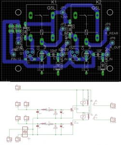
    Diagram of the hook module - You need the wiring diagram of the hook module.

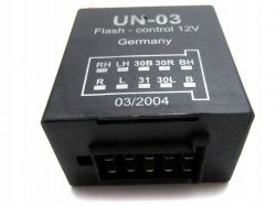
    Instead, 5c006 wanted to insert UN -07
    But it doesn't have a pin schedule for sure it's something other than UN-03.
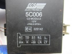
    Diagram of the hook module - You need the wiring diagram of the hook module.

    Diagram of the hook module - You need the wiring diagram of the hook module.

    In the 5c006 module:
    RT R entrance from right direction bulb
    RR output to the right trailer direction bulb
    31 mass
    +30 plus 12
    LT L entrance from left direction bulb
    LR output to the left bulb of the trailer direction

    Does anyone know what the pins in the UN -07, UN-03 module are for?

Topic summary

A user seeks a wiring diagram for a universal hook module compatible with trailers, specifically one available on Allegro. The discussion reveals that the module's function is to prevent overload on the car's electrical system and may include features like distinguishing between different bulb types. Several users suggest checking the trailer's socket for issues, as common problems include poor connections or incorrect wiring. The conversation also touches on the use of transistors and relays in the module's design, with recommendations for specific components like diodes to protect against electrical faults. The user shares their experience with a Volvo V40 and discusses the wiring discrepancies between the car and trailer. Various relay models and circuit designs are mentioned, along with suggestions for software to aid in circuit design.
Summary generated by the language model.
ADVERTISEMENT