Hello,
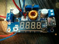
I bought a DC / DC power supply system for XL4015 on a well-known website and I have a problem with voltage regulation. The problem repeats for the second time, previously I complained about the entire system at the seller and got a new one, working properly. The first and second system worked properly until I set 12VDC, I loaded it with a 21W / 12V bulb (about 1.7A), then I turned off the mains power of the entire system with this connected load and turned it on again then the bulb only flashed and burned out and the output was already voltage equal to input approx. 35VDC. To reduce the mains voltage, I used Trafo 230 / 24VAC (4A, 100VA), then the bridge rectifier at the OUTPUT from the bridge is 35VDC and I gave it to the INJ of the system.
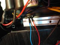
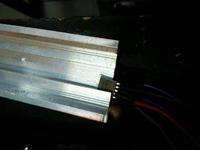
I noticed that the stabilizer LM 317 and XL4015 used in the system get very hot even when idle, so I desoldered and placed them on large heat sinks and connected with wires. The LM 317, which has a current of 1.5A, replaced the LM 338 (5A). Unfortunately, it did not help either, because as I described, it was enough to take the power supply and reconnect it to probably damage the XL4015 with a current of 5A.
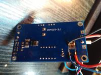
DC / DC power supply system data on the XL4015 provided by the distributor:
- input voltage 4 - 36V
- output voltage 1.25 - 32V
-current 4.5A (max 5A)
- max power 75W
- working temperature -40 +85 degrees
- efficiency 96% (max)
- frequency of 180 kHz
- short-circuit protection (limit 8A)
- voltmeter accuracy: +/- 0.05V
-Thermal protection
- no protection against reverse connection
LED display - voltage, current and power measurement.
Smooth regulation of the output voltage with a potentiometer
Input voltage measurement LED IN.
Output voltage measurement indication LED OUT
Ability to turn off the voltmeter with the left button
The ability to switch the measurement with the right button
1 - input voltage measurement
2 - measurement of the output voltage
3 - output current measurement
4 - output power measurement
5 - alternating display of all measurements.
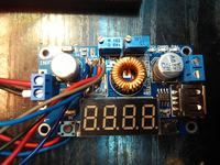
I wanted to use this seemingly great circuit to build a "workshop" power supply so that certain parameters can be set. Unfortunately, a simple resistive load damages it. What am I doing wrong? How to check if the XL4015 is actually damaged?
The IN and OUT voltage measurement works, switching with the right button switches individual measurements, so probably the XL4015 has died, but why?
When I buy a new one, how to secure it so as not to replace it every now and then?
I bought a DC / DC power supply system for XL4015 on a well-known website and I have a problem with voltage regulation. The problem repeats for the second time, previously I complained about the entire system at the seller and got a new one, working properly. The first and second system worked properly until I set 12VDC, I loaded it with a 21W / 12V bulb (about 1.7A), then I turned off the mains power of the entire system with this connected load and turned it on again then the bulb only flashed and burned out and the output was already voltage equal to input approx. 35VDC. To reduce the mains voltage, I used Trafo 230 / 24VAC (4A, 100VA), then the bridge rectifier at the OUTPUT from the bridge is 35VDC and I gave it to the INJ of the system.
I noticed that the stabilizer LM 317 and XL4015 used in the system get very hot even when idle, so I desoldered and placed them on large heat sinks and connected with wires. The LM 317, which has a current of 1.5A, replaced the LM 338 (5A). Unfortunately, it did not help either, because as I described, it was enough to take the power supply and reconnect it to probably damage the XL4015 with a current of 5A.
DC / DC power supply system data on the XL4015 provided by the distributor:
- input voltage 4 - 36V
- output voltage 1.25 - 32V
-current 4.5A (max 5A)
- max power 75W
- working temperature -40 +85 degrees
- efficiency 96% (max)
- frequency of 180 kHz
- short-circuit protection (limit 8A)
- voltmeter accuracy: +/- 0.05V
-Thermal protection
- no protection against reverse connection
LED display - voltage, current and power measurement.
Smooth regulation of the output voltage with a potentiometer
Input voltage measurement LED IN.
Output voltage measurement indication LED OUT
Ability to turn off the voltmeter with the left button
The ability to switch the measurement with the right button
1 - input voltage measurement
2 - measurement of the output voltage
3 - output current measurement
4 - output power measurement
5 - alternating display of all measurements.


I wanted to use this seemingly great circuit to build a "workshop" power supply so that certain parameters can be set. Unfortunately, a simple resistive load damages it. What am I doing wrong? How to check if the XL4015 is actually damaged?
The IN and OUT voltage measurement works, switching with the right button switches individual measurements, so probably the XL4015 has died, but why?
When I buy a new one, how to secure it so as not to replace it every now and then?


