Hello.
Below I present a description of the step-down converter based on the LM2596S-ADJ chip.
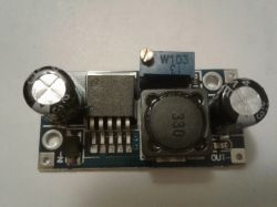
The prices of the converter start on Aliexpress from less than $ 0.60 with shipping, prices with shipping on Polish auction portals start from about PLN 7.
The maximum input voltage for the converter is 35 V (the converter IC itself can withstand a higher voltage, but the limitation here is the electrolytic capacitor at the input, which here has 35 V - you can find converters with a 50 V capacitor).
The output voltage is regulated by a potentiometer in the range from 3.2 to 35 V, efficiency up to approx. 3 A.
Converter dimensions: 44 x 20 x 13 mm
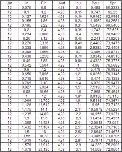
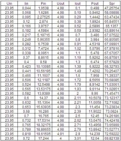
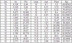
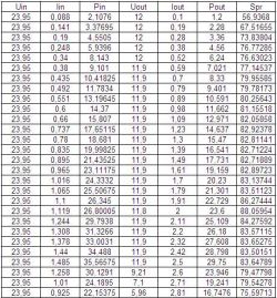
The converter was tested with an artificial load for input voltages of 12, 15 and 24 V and for output voltages of 12 and 5 V. During the tests, voltages and currents on the input and output sides of the converter were measured, power and efficiency were calculated.
Below I present the measurement results.
Input voltage 12V, output voltage 5V:
Input voltage 24V, output voltage 5V:
Input voltage 15V, output voltage 12V:
Input voltage 24V, output voltage 12V:
The diagram below shows the efficiency of the converter depending on the current consumed from the converter. We have shown the efficiency for 4 different variants.
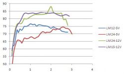
As you can see from the diagram, the efficiency of the converter is not a constant value and it can be seen here that the highest efficiency of this converter is at 15 V input voltage and 12 V output voltage, and the lowest at 24 V input voltage and 5 V output voltage.
It can also be seen that the efficiency also varies with the load on the inverter.
As you can see, the efficiency of this converter does not exceed 85%, where many sellers give even greater value in their descriptions.
The graph shows that for the input voltage of 24 V and output voltage of 12 V at approx. 2 A, the efficiency is approx. 88% - I did not notice it during the measurements, but I would consider this value as an error when reading the value from the artificial load display or an error when entering the value to Excel - it only came out when creating the chart.
It can also be seen from the measurements that it is not always possible to load the converter with 3 A and expect that it will hold the voltage at the output.
I also tested the converter temperature for the configuration where the efficiency was the worst - 24 V / 5 V. With a consumption of 2.5 A in this configuration, the converter temperature after 30 minutes was approx. 48 ° C.
Below is a link to the description of a converter based on the same circuit, but with built-in voltage measurement on the input and output sides.
https://www.elektroda.pl/rtvforum/topic3420290.html#16964656
Below I present a description of the step-down converter based on the LM2596S-ADJ chip.

The prices of the converter start on Aliexpress from less than $ 0.60 with shipping, prices with shipping on Polish auction portals start from about PLN 7.
The maximum input voltage for the converter is 35 V (the converter IC itself can withstand a higher voltage, but the limitation here is the electrolytic capacitor at the input, which here has 35 V - you can find converters with a 50 V capacitor).
The output voltage is regulated by a potentiometer in the range from 3.2 to 35 V, efficiency up to approx. 3 A.
Converter dimensions: 44 x 20 x 13 mm
The converter was tested with an artificial load for input voltages of 12, 15 and 24 V and for output voltages of 12 and 5 V. During the tests, voltages and currents on the input and output sides of the converter were measured, power and efficiency were calculated.
Below I present the measurement results.
Input voltage 12V, output voltage 5V:

Input voltage 24V, output voltage 5V:

Input voltage 15V, output voltage 12V:

Input voltage 24V, output voltage 12V:

The diagram below shows the efficiency of the converter depending on the current consumed from the converter. We have shown the efficiency for 4 different variants.

As you can see from the diagram, the efficiency of the converter is not a constant value and it can be seen here that the highest efficiency of this converter is at 15 V input voltage and 12 V output voltage, and the lowest at 24 V input voltage and 5 V output voltage.
It can also be seen that the efficiency also varies with the load on the inverter.
As you can see, the efficiency of this converter does not exceed 85%, where many sellers give even greater value in their descriptions.
The graph shows that for the input voltage of 24 V and output voltage of 12 V at approx. 2 A, the efficiency is approx. 88% - I did not notice it during the measurements, but I would consider this value as an error when reading the value from the artificial load display or an error when entering the value to Excel - it only came out when creating the chart.
It can also be seen from the measurements that it is not always possible to load the converter with 3 A and expect that it will hold the voltage at the output.
I also tested the converter temperature for the configuration where the efficiency was the worst - 24 V / 5 V. With a consumption of 2.5 A in this configuration, the converter temperature after 30 minutes was approx. 48 ° C.
Below is a link to the description of a converter based on the same circuit, but with built-in voltage measurement on the input and output sides.
https://www.elektroda.pl/rtvforum/topic3420290.html#16964656
Cool? Ranking DIY


