logo elektroda
logo elektroda
X
logo elektroda

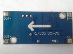
Description of the step down converter based on the XL4005

grala1 18573 54
ADVERTISEMENT
Treść została przetłumaczona polish » english Zobacz oryginalną wersję tematu
  • Hello.
    Below I present a description of the step-down converter based on the XL4005E1 chip.
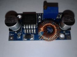
    Description of the step down converter based on the XL4005
    Description of the step down converter based on the XL4005
    The prices of the converter start on Aliexpress from less than $ 0.95 with shipping, prices with shipping on Polish auction portals start from about PLN 12.
    The maximum input voltage for the converter is 32V DC.
    The output voltage is regulated with a multi-turn potentiometer in the range from about 0.8 to 30 V, current efficiency up to about 5 A. Operating frequency 300kHz, drop out about 0.6V, built-in thermal, short-circuit and overload protection.
    Converter dimensions: 43 x 21 x 14 mm
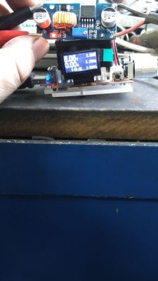
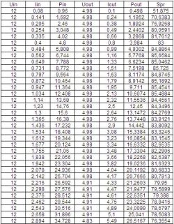
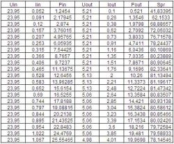
    The converter was tested with an artificial load for input voltages of 12 and 24 V and for output voltages of 5 V. During the tests, the voltages and currents on the input and output sides of the converter were measured, and the power and efficiency were calculated.
    Below I present the measurement results.
    Input voltage 12V, output voltage 5V:
    Description of the step down converter based on the XL4005
    Input voltage 24V, output voltage 5V:
    Description of the step down converter based on the XL4005
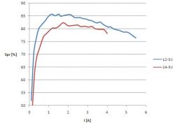
    Fitness graph:
    Description of the step down converter based on the XL4005
    It can be seen that the efficiency of the converter depends on its supply voltage, in this case the lower the supply voltage, the higher the converter efficiency.
    When performing the above measurements on an artificial load, during the load change, I turned the load control encoder too much, which resulted in the load of the converter with a current of over 7A for a few seconds, which caused its damage. It was not accompanied by any special effects, just the blue LED on the converter board went out. In the idle state, the maximum output voltage after damage is about 1.5V, but after applying a load, the voltage at the output disappears. The XL4005 chip and the Schottky diode were damaged.
    As there were supposed to be more measurements, I decided to buy another converter and repeat the unfinished measurement with 24V input voltage and 5V output voltage, and also make measurements for other voltages. The second inverter was purchased from another vendor.
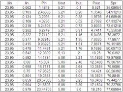
    Here are the results of the repeated measurement for the new converter - 24V / 5V:
    Description of the step down converter based on the XL4005
    Measurements could not be completed. As you can see, with a load of 3.6A, after a dozen or so seconds it sizzled, hissed and there was smoke with an unpleasant smell of burning electronics.
    The effect of this can be seen in this photo:
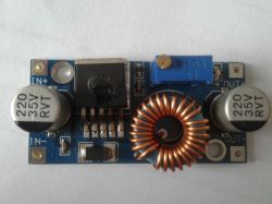
    Description of the step down converter based on the XL4005
    There was a hole in the XL4005 chip, and the Schottky diode was damaged as in the previous converter as a result of too much load.
    Both converters were tested with exactly the same equipment and with the same voltages, but between the two copies you can notice a difference in efficiency, although at first glance they look identical.
    Below is a comparison of the efficiency of these converters for 24 / 5VDC voltages:
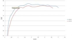
    Description of the step down converter based on the XL4005
    Series 1 - the first converter damaged by excessive load, series 2 - the second converter where a hole was created in the circuit at 3.5A.
    Despite the built-in security features, neither of them had worked.
    The temperature did not exceed 40 ° C during these tests.

    I damaged the first inverter myself by loading it too much, which showed that the overload protection did not work, the second one damaged by itself at a load of about 70% where the temperature of the system did not exceed 40 ° C.
    I don't know if I came across a flawed copy or if it was some inept fakes.
    Maybe someone who has such a converter will write his experience of using it.

    Below are links to the descriptions of two other DC-DC step-down converters on the LM2596 chip, where one has a built-in voltmeter to measure the input and output voltage.
    https://www.elektroda.pl/rtvforum/topic3420289.html#16966161
    https://www.elektroda.pl/rtvforum/topic3420290.html#16964656
    Below is the efficiency diagram for the input voltage of 24VDC, output voltage of 5VDC for the converter based on the LM2596 system, the converter based on the LM2596 system + built-in measurement of the input and output voltage and two converters based on the XL4005 system tested in this article:
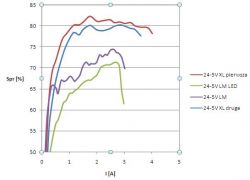
    Description of the step down converter based on the XL4005
    It can be easily seen that the converters based on the XL4005 achieve the best efficiency.

    Cool? Ranking DIY
    About Author
    grala1
    VAG group specialist
    Offline 
    grala1 wrote 9760 posts with rating 4847, helped 1477 times. Live in city Kalisz. Been with us since 2006 year.
  • ADVERTISEMENT
  • #2 16996335
    Anonymous
    Level 1  
  • ADVERTISEMENT
  • #3 16996667
    gulson
    System Administrator
    The user of grala1 helps me a lot by testing the electronic modules. As soon as I found out that his converter burned down during the tests, I immediately sent a new one. It turned out that the second was also damaged. I don't know if the heat sink would help, but I suggest avoiding this module if your system is a bit more power hungry. And people buy it in thousands. The gra1 tests are not ordered by the producers, I test them ourselves and we buy the modules ourselves, so we are not afraid to write the truth. Interesting if the interference test fell out after the bands.

    If anyone would be interested in similar reviews, have some measuring equipment and a light pen, feel free to do so.
  • #4 16996744
    Arek_v1
    Level 14  
    At most auctions in Poland with such converters it is written to use a heat sink, so there must be something in it :P
  • #5 16996775
    prosiak_wej
    Level 39  
    Since col. @ grala1 I am testing modules, maybe I will propose DPS converters.

    At the end of November 2017 I bought a DPS5005 in the GoTronik store, it did not regulate the voltage at all, in the idle state, "turned off" it was about 5V. A complaint has been sent. At the end of December I got a new one (the one sent was supposedly fixed) - it worked. Whole three days. During the measurement, the LED reset and then went out forever. In 2017, I sent a complaint. About a week ago, after asking for a new copy (the statutory 14 calendar days have passed, no information from GoTronik) I got a package with a "new" converter. After connecting, it turned out that it works in the same way as the first one from November. The third time I sent a complaint requesting a refund.

    I don't know if these converters are defective, or if GoTronik has such ugly practices that it sends used, allegedly repaired copies? Currently, only they sell these modules on Allegro, so there is no one else to buy from. Or maybe these converters are quite good and have little failure, and I was unlucky to buy it in the wrong store and I was supposed to buy it directly from China? I would pay less, and in the end I would have a working power supply faster (because from the end of November 2017 I only have the base - the Eltek 50V power supply set to 53V).

    Added after 55 [seconds]:

    Arek_v1 wrote:
    At most auctions in Poland with such converters it is written to use a heat sink, so there must be something in it :P


    It is strange that the temperature of 40 ° kills the system, i.e. releases magic smoke from it ;)
  • #6 16996777
    gulson
    System Administrator
    Arek_v1 wrote:
    At most auctions in Poland with such converters it is written to use a heat sink, so there must be something in it :P

    It would not have had time to remove the heat if the demand for electricity increased rapidly. Besides, grala1 watched the temperature. A protection that did not work should have worked. And it didn't even come to extreme conditions.

    Added after 2 [minutes]:
    prosiak_wej wrote:
    At the end of November 2017, I bought a DPS5005 in the GoTronik store

    It's an interesting idea. It probably costs a little more, and not everyone can afford to buy it. In the beginning, we deal with what is bought in thousands. However, more expensive modules and the measuring devices themselves will also be tested.
  • #8 16997083
    BOOM i ZONK
    Level 21  
    I believe that the diode (SS54) used there causes the internal MOSFET to "burn", especially in the event of its short circuit. Datasheet recommends using a diode with an average forward current of 10A and not only 5A, as in the case of SS54. Of course, I may be wrong ...
  • #9 16997113
    Anonymous
    Anonymous  
  • #10 16997699
    jnk0le
    Level 18  
    As for this short-circuit resistance, I have already managed to make a resistive divider out of one LM (~ 10? ;) .
  • #11 16997873
    TechEkspert
    Editor
    Is the USB DVB-T receiver on RTL2832U with alternative software would it be suitable for estimating the level of noise emitted by the converter?
  • ADVERTISEMENT
  • #12 16998339
    barti10
    Level 16  
    Colleague prosiak_wej had bad luck with this inverter because they are really well done. I have a workshop power supply built on the DPS 5015 module and it works great. I bought it directly from a Chinese man and I would not have built one myself for a similar amount. The modules are compact, the assembly is very clean, mainly SMD, someone has been working on the project for a while. There are a lot of videos on the internet where people torture them in different ways and that made me buy them.
  • ADVERTISEMENT
  • #13 16998466
    Anonymous
    Anonymous  
  • #14 16998749
    prosiak_wej
    Level 39  
    Col. @ barti10 - what voltage from the power supply did you give to the converter? Slightly over 50V to get 50V in the output, say 48V and the inverter limited to 45v?
  • #15 16999889
    tomus2k
    Level 27  
    XL4015 is in use and doing quite well ....

    In fact, the XL4005 has a problem and likes to go up in smoke
  • #16 16999917
    Anonymous
    Level 1  
  • #17 16999991
    Anonymous
    Anonymous  
  • #18 17000040
    kkknc
    Level 43  
    Waiting for lot XL 4015. So I can test how it arrives.
  • #19 17000796
    rafalekrav40
    Level 12  
    kkknc wrote:
    Waiting for lot XL 4015. So I can test how it arrives.


    I am waiting for the tests. Greetings :)
  • #20 17000838
    Anonymous
    Level 1  
  • #21 17001061
    mariomario
    Level 18  
    A very nice initiative with testing these cheap modules from China, I would love to see and, if possible, also added tests of various modules from China (not necessarily only converters). Such a directory + tests of all available modules + detailed descriptions + possible defects / comments
  • #22 17001093
    Jawi_P
    Level 36  
    I have used these ready modules more than once. One module fell on several pieces.
    It fell not from a heavy load, because more than 07-08A was never taken from the output, I suspect it was from a pin at the input, although I gave a 30V transil. I know that the transils have such a spread that ...
    Or by himself?

    Do you write that you are waiting for these chips, i.e. not modules, but only chips? Can you buy it somewhere? Some time ago (2-3 years, maybe more) I was looking for only modules that were available from the Chinese.
  • #23 17001247
    barti10
    Level 16  
    Buddy prosiak_wej, my power supply was made from "przydasi" and I did not have such luck to use the full range of regulation. I power the converters with 36v DC and the adjustment range is limited to 30v. The manufacturer himself recommends a few volts of I / O difference.
  • #24 17001357
    Anonymous
    Anonymous  
  • #25 17001406
    mkpl
    Level 37  
    It would take a deeper look at these converters.

    I have used LM2596 converters many times. In fact, the XL4005 is a slightly stronger clone of the original. Generally, the modules worked well. Their maximum current was specified at 3A, but at this value the output capacitors were already heating up (with continuous consumption). The same goes for the diode.


    The system also required an additional LC filter at the output. Finally, I changed the capacitors to the samyoung NXH (Jamicon TB will also come), then a 15 ~ 25uH choke and a 100uF + 100nF capacitor. The converter started to work cleanly (small ac ripple at the output).

    However, in these XL4005 modules it must have mixed up something for the "majfrend". Same PCB and they squeeze 5A out of it with the same efficiency. It must burn unless the efficiency reaches over 90 several%.

    Generally the weak points I see:
    - Small cooling area of the XL4005 system
    - Small area (no) of cooling the ss54 diode (it also gives off heat)
    - Choke not optimally selected for the operating voltage range (I recommend looking at the LM2576 or 96 data sheet for example)
    - Input and output capacitors do not have a chance to withstand such a high ripple current (they are not adapted to pulse operation, and they are for lower current).
    - Non-optimally selected choke. Changing it will significantly improve efficiency.
    - No LC filter
    - No dynamic branches.

    Possible causes of damage:
    - SS54 diode overheated, which went short.
    - Saturation of the output choke.

    Someone asked about non-linear voltage regulation. Such non-linearity in such a system will always occur. This is because the potentiometer is physically connected in series with the resistor. It can be changed, but I don't know if it will get better.


    One more piece of advice. For those 5A, it is worth gently lifting the choke and potentiometer (so that the pins do not stick out from the other side of the pcb) and screw the module to a piece of aluminum sheet through a piece of thermally conductive silicone.

    For delicate systems, e.g. if it is to be a charger, you need to build a crowbar that will disconnect the charger faster than, for example, the charged phone will be damaged.

    If anyone wanted, I can test such a system and adjust it to the required voltage range.
    best regards
  • #26 17001466
    yogi009
    Level 43  
    mkpl wrote:
    The system also required an additional LC filter at the output. Finally, I changed the capacitors to the samyoung NXH (Jamicon TB will also come), then a 15 ~ 25uH choke and a 100uF + 100nF capacitor. The converter started to work cleanly (small ac ripple at the output).


    Can you show it on the diagram? I think it will be useful to posterity in such a thread.
  • #27 17001482
    kkknc
    Level 43  
    It seems that somewhere like this inverter is in my place. It was supposed to power the phones, but it crumpled terribly with the load.

    Added after 8 [hours] 16 [minutes]:

    XL 4015E1
    Load as in the picture.
    The diode D1 gets warm the fastest, even hot. Then the choke and the circuit itself.
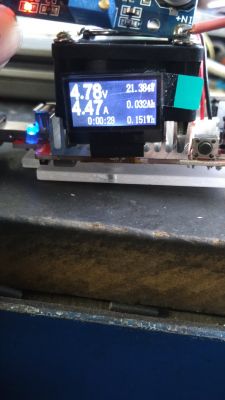
    Description of the step down converter based on the XL4005 Description of the step down converter based on the XL4005
    You would have to do a long test and put a heavier load.
  • #28 17001951
    tomus2k
    Level 27  
    kkknc wrote:

    XL 4015E1
    Load as in the picture.
    The diode D1 gets warm the fastest, even hot. Then the choke and the circuit itself.
    You would have to do a long test and put a heavier load.

    I told you the X4015 is fine.
    And for long-term tests, I recommend equipping the board with a heat sink :D
  • #29 17002146
    Anonymous
    Anonymous  
  • #30 17002240
    yogi009
    Level 43  
    As usual with such converters, I would ask you to add to the test waveforms showing where and how this system "sows".

Topic summary

The discussion revolves around the XL4005E1 step-down converter, highlighting its specifications, performance issues, and user experiences. Users report problems with interference affecting FM radio bands, inefficiencies under load, and failures during testing. The converter's maximum input voltage is 32V DC, with adjustable output from 0.8V to 30V and a current capacity of up to 5A. Concerns are raised about the quality of components, particularly the SS54 diode, which may lead to failures. Comparisons are made with other models like the LM2576 and LM2678, which are noted for better reliability. Users suggest using heat sinks and additional filtering to mitigate issues. The conversation also touches on the need for thorough testing of these converters and the potential for collaborative testing initiatives within the community.
Summary generated by the language model.
ADVERTISEMENT