logo elektroda
logo elektroda
X
logo elektroda

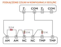
Satel 3EOL/NC Connection Diagram: Connecting Opal Detector for Beginner Installers

kuba-1255 17772 17
ADVERTISEMENT
Treść została przetłumaczona polish » english Zobacz oryginalną wersję tematu
  • #1 16318059
    kuba-1255
    Level 8  
    I warmly welcome,
    I am a beginner installer, I am looking for a scheme to connect an Opal detector in 3EOL / NC configuration. Yes, I know this scheme is available
    in the user manual, but he doesn't tell me anything. Once, e.g. to 2EOL / NC in the CA-6 control panel, there was a diagram that I understood. However
    there are new patterns in the new exchanges that I don't understand. If someone could draw to me in the inputs, what to connect, where to give what resistor. As it once was in Satellite - simple and understandable.

    Thanks in advance.
    Cuba
  • ADVERTISEMENT
  • #2 16318090
    sosarek

    Level 43  
    Which control panel are you going to connect sensors to in this configuration, because not everyone supports 3EOL / NC.
    The scheme itself is available for example here .
    Helpful post? Buy me a coffee.
  • #3 16318094
    kuba-1255
    Level 8  
    Satel Integra 64 plus. This exchange supports, I paid attention to it.
    That's not how I understand this pattern, it's the same in the instructions.
  • ADVERTISEMENT
  • #4 16318203
    bhtom
    Level 38  
    Hello,

    What is meant here. The control panel recognizes 3 states of the line. Violation, tampering and masking.
    So much.

    Best regards.
  • #5 16318226
    wotik
    Level 20  
    It may be helpful to visualize such (and other) configurations in this program (option Types of detector lines ) ...
  • Helpful post
    #7 16318292
    dariusz.bembenek
    Stationary Alarms specialist
    Dude, please don't overdo it. Imagine that where it says:
    A - these are NC and NC contacts
    M - these are AM and AM contacts
    T - these are TMP, TMP contacts.
    There really is nothing more to rozkminy.
  • ADVERTISEMENT
  • #8 16318309
    wotik
    Level 20  
    bhtom wrote:
    The control panel recognizes 3 states of the line

    If it's four: normal, alarm, tamper and masking ... ;-P
  • Helpful post
    #9 16318310
    dariusz.bembenek
    Stationary Alarms specialist
    OK let it be:
    Satel 3EOL/NC Connection Diagram: Connecting Opal Detector for Beginner Installers
  • ADVERTISEMENT
  • #10 16318319
    sosarek

    Level 43  
    dariusz.bembenek wrote:
    OK let it be:

    The worst is that
    kuba-1255 wrote:
    I am a beginner installer

    kuba-1255 wrote:
    such a scheme is available
    in the user manual, but he doesn't tell me anything

    kuba-1255 wrote:
    there are new patterns in the new exchanges that I don't understand

    Without the ability to read diagrams, take the assembly of the system, if there are problems with the basics, the question is what will happen next ...
    Helpful post? Buy me a coffee.
  • Helpful post
    #11 16318330
    dariusz.bembenek
    Stationary Alarms specialist
    Do not let your hands fall. I hope that the above scheme will allow you to at least understand the other schemes available in the current instructions. I also preferred the previous ones, because "visually" they showed in what hole what cable to screw in. Well ... times are changing, and it's just a stupid, simple scheme ;) You have to skillfully use what is.
  • #12 16318335
    sosarek

    Level 43  
    kuba-1255 wrote:
    however, I am still asking for an explanation or a diagram.

    If even that
    dariusz.bembenek wrote:
    OK let it be:
    Satel 3EOL / NC connection diagram. How to connect

    is incomprehensible to you - so excuse me, invite an INSTALLER to help you.
    Helpful post? Buy me a coffee.
  • #13 16318337
    kuba-1255
    Level 8  
    Dariusz.bembenek thank you very much for the diagram.
    And to a colleague cutting out words from the context of a sentence, I will say that the alarm works, and not one. But I did not understand this pattern - it probably does not affect installations. And to make no sense at once to criticize someone for not understanding the pattern. Not everyone is as "smart" as a friend. And this diagram from my colleague Dariusz.bembenek I fully understand, they were once in the instructions.

    best regards
  • #14 16318376
    sosarek

    Level 43  
    kuba-1255 wrote:
    a friend cutting out words from a sentence contact

    Out of context, if anything. And this is only to quote your statements that you have changed / removed from posts.
    kuba-1255 wrote:
    I will say that the alarm works

    I only wonder how its elements are selected, how the current balance falls, etc.
    kuba-1255 wrote:
    I didn't understand this pattern - it probably doesn't affect installations

    But it shows a lack of basic knowledge.
    kuba-1255 wrote:
    Not everyone is as "smart" as a friend.

    I do not consider myself wise, I have been in the profession for 17 years, I am still learning new solutions whenever possible.
    After all, I would advise my colleague to "lick" the basics.
    Helpful post? Buy me a coffee.
  • #15 16318390
    Anonymous
    Level 1  
  • #16 16318401
    kuba-1255
    Level 8  
    Let's start with the fact that one post I fell asleep because, I received the diagram. And the post concerned the fact that I would need such a scheme. So it makes no sense to be misleading - I do not understand this pattern. I also know about the current balance,
    Can you choose the wrong equipment for the control panel?
    I don't think so, there are different models, but each one fits into a central unit. Detectors are known to be better and worse but each one fits the control panel.

    And through the prism of one scheme, I was rated as a mere "fool" who has no idea about anything. I do not want to pay for the services of installation companies. Unfortunately....
  • #17 16318423
    sosarek

    Level 43  
    kuba-1255 wrote:
    Can you choose the wrong equipment for the control panel?

    You would be surprised, I was more concerned with the selection of system elements for a given object, their arrangement, etc.
    kuba-1255 wrote:
    And through the prism of one scheme, I was rated as a mere "fool" who has no idea about anything.

    If you received it this way - sorry, that wasn't the point, I just wanted you to get acquainted with the basics and learn how to read connection diagrams, it's not difficult, just sit down, draw out the input / output on a piece of paper and try to figure it out (everybody ever learned it).
    Helpful post? Buy me a coffee.
  • #18 16318436
    kuba-1255
    Level 8  
    And you see the arrangement was about and here I agree. In this case, you can make a system that protects nothing.
    Generally, I understand the schematics, it was one exception.

Topic summary

The discussion revolves around connecting an Opal detector in a 3EOL/NC configuration to a Satel Integra 64 plus control panel. The original poster, a beginner installer, seeks a clear connection diagram, as the user manual is not comprehensible. Various responses highlight the importance of understanding the control panel's capabilities, which can recognize three states of the line: violation, tampering, and masking. Some users suggest using visualization software for better understanding, while others provide a diagram link and emphasize the need for basic knowledge in reading schematics. The conversation also touches on the challenges faced by beginners in interpreting complex diagrams and the importance of proper equipment selection for effective system installation.
Summary generated by the language model.
ADVERTISEMENT