logo elektroda
logo elektroda
X
logo elektroda

Connecting the electric projector screen under the fibaro module

mat008 4560 7
ADVERTISEMENT
Treść została przetłumaczona polish » english Zobacz oryginalną wersję tematu
  • #1 16339988
    mat008
    Level 7  
    Hello, I would like to point out in advance that operating a test tube is the maximum of my electrical knowledge so I apologise in advance if I write something wrong. I have an electric screen for a projector , unfortunately bought used and I have no instructions from it or even the name of the manufacturer. It currently works on a "remote control" connected by cable and on a radio remote control. I want to connect this screen to the fibaro roller shutter module FGR 221
    In the fibaro wiring diagram from the motor we have three wires, but from my screen I have four wires (through all this confusion) yellow-green with brown and blue with brown. What is interesting to me is when I control the screen down and up the phase still goes to the same set of wires e.g. yellow-green with brown (or if the plug in the socket is reversed the phase goes to blue with brown). Can someone explain to me where this fourth wire (second phase?) comes from and how to connect this to the above module?
  • ADVERTISEMENT
  • #2 16340110
    jdubowski
    Tube devices specialist
    mat008 wrote:
    however from my screen I have four wires (through all this confusion) yellow-green with brown and blue with brown. What is interesting to me is when I control the screen down and up the phase still goes to the same set of wires e.g. yellow-green with brown (or if the plug in the socket is reversed the phase goes to blue with brown). Can someone explain to me where this fourth wire (second phase?)
    comes from.

    Yellow-green is not that the protective conductor?
    And put down that neon tester, measure it with an ohmmeter without power, then you'll work out what connects to what - the neon tester falsely shows phase where there is none (at least not directly).
  • ADVERTISEMENT
  • #3 16340155
    mat008
    Level 7  
    Depending on how the plug is inserted into the socket, the yellow-green may also be followed by a phase (at least for the test tube) , so it is unlikely to be protected
  • ADVERTISEMENT
  • #4 16340178
    sosarek

    Level 43  
    mat008 wrote:
    I have an electric screen for a projector , unfortunately bought used and I do not have any instructions from it or even the name of the manufacturer
    .
    Does it not have any nameplate? Post some pictures of the drive.
    Company Account:
    Z
    Pka, Poznań, 60-850
    Helpful post? Buy me a coffee.
  • ADVERTISEMENT
  • #5 16340977
    mat008
    Level 7  
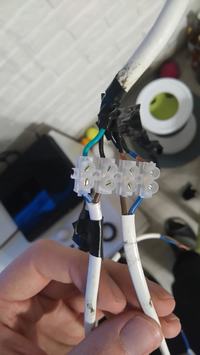
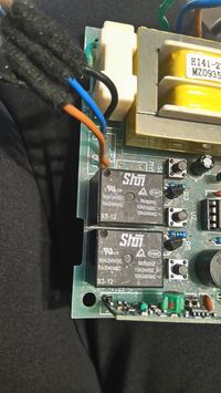
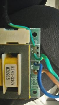
    Thanks for your interest. Unfortunately the plate is missing, and I can't take a picture of the drive because the screen is fixed in the ceiling in a re-wall. I was able to dismantle the remote control, which is wired. Photo 1 shows the connection of the 4-wire cable that goes from the screen to the two 2-wire cables of the remote control. Photo no. 2 shows the 3 wires from the remote control to the screen, photo no. 3 shows the 3 wires from the plug to the board plus one from the board to the screen (yellow and green, there is a protective conductor sign but I am not sure if this is its role). Maybe you can determine something on this basis?
    Connecting the electric projector screen under the fibaro module .
    Connecting the electric projector screen under the fibaro module .
    Connecting the electric projector screen under the fibaro module
  • #6 16341477
    jdubowski
    Tube devices specialist
    mat008 wrote:
    in photo #3 you can see three wires from the plug to the board plus one from the board to the shield (yellow-green, there is a protective conductor mark but I am not sure if that is the role).
    .

    Then take an ohmmeter and measure the mains lead - the protective contact in the plug has a connection to that yellow/green lead?

    mat008 wrote:
    Depending on how you plug the plug into the socket, the yellow-green can also go behind the yellow-green (at least for the test tube)
    .

    Put down that test tube, instead check the continuity of the yellow-green wire between the plug and the circuit, and that the pin in the socket is earthed.

    mat008 wrote:
    Photo #2 shows the 3 wires from the remote control to the screen,
    .

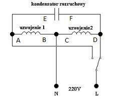
    Presumably feeding power between black and blue gives movement one way, and between black and brown the other way. Presumably there is a motor with two symmetrical windings + capacitor:

    Connecting the electric projector screen under the fibaro module .

    Measure the resistances between the motor leads (after disconnecting the driver) and zap.
  • #7 16342529
    mat008
    Level 7  
    Looking at the dismantled remote control I only saw that the yellow-green wire at the remote control output was stippled, with a blue wire. And the black wire from the remote control was stippled with blue. Hence the two blue and two brown wires seen in photo 1. But maybe let's just go back to the screen. After measuring all combinations of these four wires (green-yellow, blue, black and brown) with a meter. Only between black and blue did the meter show 1.33. In the other combinations it was always 1. I set the meter to 20k
    And so the yellow-green has a transition from the plug all the way to the remote control output.

    Also setting the meter to volts I made the following measurements (I gave the plug so that zero was on the blue wire of the plug, the socket didn't happen to have a ground pin). Screen up, blue 98, brown 230, black 0, yellow green 47, when screen down then brown and blue swap values, the other two unchanged

    That is, I give the black from the screen under zero to the socket, and the brown and blue under Fibaro 01 and 02, plus zero and phase from the socket under Fibaro. Is that correct?
  • #8 16366171
    mat008
    Level 7  
    Connection showed up correct, thanks for helping me figure out what's what

Topic summary

The discussion addresses connecting a used electric projector screen, lacking manufacturer details and instructions, to a Fibaro roller shutter module FGR-221. The screen's wiring includes four wires (yellow-green, brown, blue, and black), while the Fibaro module expects three wires from the motor. The yellow-green wire is suspected to be a protective earth conductor, but measurements showed it may carry phase depending on plug orientation. An ohmmeter was recommended to verify wire functions and continuity, as a neon tester can give false phase indications. Voltage measurements indicated that the blue and brown wires swap voltage values when the screen moves up or down, while black and yellow-green remain relatively constant. Resistance measurements between black and blue wires showed a distinct value, suggesting motor winding connections. The screen likely uses a motor with two symmetrical windings and a capacitor. The final conclusion confirmed the correct wiring connection after testing, enabling integration with the Fibaro module.
Summary generated by the language model.
ADVERTISEMENT