FAQ
TL;DR: Drutex radio shutters expose two control wires; "You can't connect them together to neutral." For remote-only, connect L, N, and PE, insulate the control leads, then program the remote. This FAQ helps DIYers safely wire five‑lead Drutex/INEL shutters. [Elektroda, Anonymous, post #17722478]
Why it matters: Miswiring control leads can instantly damage the actuator and create a safety risk.
Quick Facts
- Typical remote-only hookup: N→grey, L→blue, PE→green-yellow; insulate black and brown. [Elektroda, Anonymous, post #17722377]
- Built-in radio receiver: connect only L and N, then enroll the remote. [Elektroda, Anonymous, post #17722227]
- Do not bridge both control wires to N; it can destroy the actuator. [Elektroda, Anonymous, post #17722478]
- Many installations present a 5‑wire motor lead bundle. [Elektroda, tinca2, post #17722090]
- Safety note: "You can do great harm to someone with an incompetent connection." [Elektroda, Homo_toxicus, post #17722325]
How do I wire a Drutex radio shutter with no wall switch?
Use this remote-only setup. 1) Connect N to grey, L to blue, and PE to green-yellow. 2) Cap/insulate black and brown (manual control leads). 3) Program/enroll the remote to the actuator per instructions. This isolates manual control and uses the built-in radio safely. [Elektroda, Anonymous, post #17722377]
What are the black and brown wires for on Drutex motors?
They are manual control inputs. The internal radio module shorts either black or brown to N to run down or up. Do not tie them together or to N simultaneously. Use a momentary switch if adding manual control. [Elektroda, Anonymous, post #17722478]
Can I connect both black and brown to neutral (N)?
No. Connecting both control leads to N at once can burn the actuator. Quote: "You can't connect them together to neutral because you will eat up the actuator." Keep one open while the other is active. [Elektroda, Anonymous, post #17722478]
If my manual shows blue as LIVE, should I follow it?
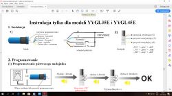
Treat it as suspect. A user flagged such a diagram as modified, lacking logos, and mixing colors. Verify the manual’s origin and model labeling before wiring. Avoid undocumented color assignments. [Elektroda, Homo_toxicus, post #17722445]
Which wires do I connect when using only the remote control?
Connect L and N to power the motor, and leave control leads unused. Then program the remote to the actuator; the radio receiver is built in. [Elektroda, Anonymous, post #17722227]
What is the green-yellow wire for?
It is the protective earth (PE). Always connect PE for safety and compliance when powering the shutter motor. Do not leave PE floating. [Elektroda, Anonymous, post #17722377]
How many wires should I expect from the shutter motor?
Typical installations expose five conductors from the motor bundle. This includes power, earth, and two control leads for up/down. [Elektroda, tinca2, post #17722090]
How do I verify the actuator model and a manual’s authenticity?
Use manuals with manufacturer logos and clear product identification. One user shared an official INEL manual with branding on each page for the radio motor used. Avoid unattributed scans. [Elektroda, Homo_toxicus, post #17724348]
What switches work for manual control (without remote)?
Use tactile/momentary switches that feed N to either black or brown, never both. One direction must be open while the other operates. Direction mapping may swap; test briefly. [Elektroda, Anonymous, post #17722117]
What’s a safe fallback if I’m unsure about the diagram?
Stop and read the motor’s manual carefully, or hire a qualified installer. Quote: "You can do great harm to someone with an incompetent connection." [Elektroda, Homo_toxicus, post #17722325]
After wiring, the shutter moves wrong direction or not at all—what should I check?
Check that black and brown are insulated or not both tied to N. Ensure only one control lead is ever fed. Then enroll the remote correctly. Misusing both leads blocks motion or harms the motor. [Elektroda, Anonymous, post #17722478]
What connection finally worked for the OP’s Drutex shutters?
They reported success with brown-to-brown, blue-to-blue, and green-yellow to PE, with black and grey insulated. Always verify against your motor’s labeling before copying. [Elektroda, tinca2, post #17724163]
Do I need an external radio receiver for Drutex radio motors?
No. The actuator includes a built-in radio receiver. Supply L and N, then program the remote to the motor’s memory. [Elektroda, Anonymous, post #17722227]
What if my wire colors don’t match the advice here?
Color codes vary by actuator batches. One installer saw non-standard colors and wired per the manual successfully. Verify functions instead of assuming standards. [Elektroda, Anonymous, post #17722478]
 .
.
 .
.


