FAQ
TL;DR: Want to fix long gas post‑flow on a MAGNUM MIG‑MMA 220W IGBT? "A 1k resistor between the source and the gate can be installed on the gas mosfet" — a simple 1 kΩ mod suggested here. [Elektroda, stasiekb100, post #17362629]
Why it matters: This helps owners reduce wasted shielding gas during spot/tack welding while understanding warranty implications.
Quick Facts
- Stock behavior reported: gas keeps flowing ~1–2 seconds after trigger release. [Elektroda, metallhead, post #17348791]
- Suggested mod: add a 1 kΩ resistor between source and gate of the gas‑valve MOSFET. [Elektroda, stasiekb100, post #17362629]
- If still too long, adjust the LM358 op‑amp timing network (RC) for the valve hold time. [Elektroda, stasiekb100, post #17362629]
- Warranty note: “Any interference is a loss of warranty.” [Elektroda, Krzysztof Reszka, post #17354724]
- User feedback: Machine works well for home use; main gripe is post‑flow delay. [Elektroda, metallhead, post #17835790]
How do I shorten the gas shutoff delay on a MAGNUM MIG‑MMA 220W IGBT?
Use a simple hardware tweak. 1) Find the gas‑valve MOSFET on the control board. 2) Solder a 1 kΩ resistor between its source and gate to hasten turn‑off. 3) Test; if delay persists, tune the LM358 RC timing network. This targets the valve hold‑time circuit directly. Keep safety and warranty in mind when opening the unit. [Elektroda, stasiekb100, post #17362629]
Is there a front‑panel knob or menu to set post‑flow time on this unit?
No dedicated post‑flow adjustment is exposed on the front. The delay comes from an internal RC timing circuit. To change it, you must alter component values on the control board, which involves electronics work and risks warranty loss. [Elektroda, noopS, post #17351953]
What exact mod value and connection were suggested?
Install a 1 kΩ resistor between the source and gate of the MOSFET that drives the gas solenoid. This increases gate discharge and speeds valve closure after you release the trigger. [Elektroda, stasiekb100, post #17362629]
What if the 1 kΩ mod doesn’t reduce the delay enough?
Adjust the LM358‑based timing network that holds the solenoid open. Shorten the RC time constant around the LM358 controlling the valve signal. Make small changes and test, as layouts and values vary by board revision. [Elektroda, stasiekb100, post #17362629]
Which IC is involved in gas valve timing on this board?
An LM358 operational amplifier participates in the valve timing path. If a simple gate‑to‑source resistor does not suffice, modify the LM358’s RC network to shorten the hold time. [Elektroda, stasiekb100, post #17362629]
How long is the stock gas post‑flow on this machine?
The reported behavior is about 1–2 seconds of gas flow after releasing the trigger. For frequent tacks, that can feel like continuous flow between spots and waste gas. [Elektroda, metallhead, post #17348791]
Is this delay normal or a fault with my welder?
It appears normal for this board. An experienced user recognized the board and noted the gas function worked properly, suggesting it’s by design rather than a defect. [Elektroda, stasiekb100, post #17361515]
Where do I trace the gas valve driver on the PCB?
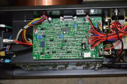
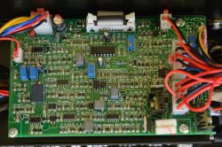
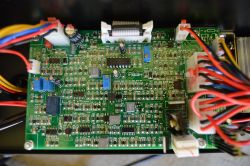
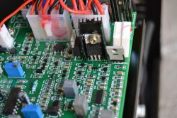
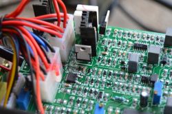
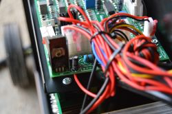
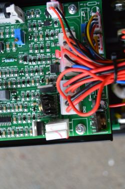
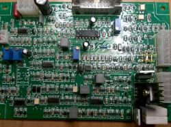
Follow the gas solenoid’s two red wires into the control board. They lead to the valve driver section and the MOSFET you’ll modify. Photograph both sides for clarity before changes. [Elektroda, metallhead, post #17360245]
Could opening the case and soldering void my warranty?
Yes. As one expert cautioned, “Any interference is a loss of warranty.” Plan mods only if you accept this risk or your warranty has expired. [Elektroda, Krzysztof Reszka, post #17354724]
Do I need to measure to find the precise RC parts on my unit?
Yes. Board revisions differ, so measure and trace to identify the exact resistor or capacitor controlling hold time on your board. “You have to measure.” [Elektroda, noopS, post #17352673]
How does this welder perform for home and hobby use overall?
The owner reports it works well and meets home project needs. The main annoyance is the extended gas post‑flow, which they had not yet modified. [Elektroda, metallhead, post #17835790]
Can someone guide me if I share board photos?
Yes. A knowledgeable user offered to indicate the resistor location from photos. Share sharp images of both sides for accurate guidance. [Elektroda, stasiekb100, post #17354526]
