logo elektroda
logo elektroda
X
logo elektroda

Wingo 3524 Photocells Installation, Remote Programming for Dual Gates, Speed Adjustment

cbdu 7497 8
ADVERTISEMENT
Treść została przetłumaczona polish » english Zobacz oryginalną wersję tematu
  • #1 16515522
    cbdu
    Level 11  
    Hello,

    Please help me with the following electronic problems:
    I have installed Wingo 3524 for 2 wings and I have a problem with:

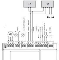
    1. Photocells (eggs) because they do not work - no reaction, i.e. I connected the following - this is how the seller advised:
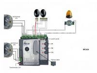
    Wingo 3524 Photocells Installation, Remote Programming for Dual Gates, Speed Adjustment
    2. I wanted to program the old 2-button remote for the second sectional gate (nice flor-s) on the second button to have 1 remote for two gates. I did as below in the video with the second button:
    https://www.youtube.com/watch?v=SN_3lqMIizc
    and now I have: 1 button opens both gates, 2 button opens the new Wingo 3524 :(
    3. It opens slowly from the 1st level of programming according to the instruction: I enter the 1st level - I hold P1 and P2 for 3 seconds. I switch to L4 ;) led and approve P1 and P2 3sec. Everything according to the instructions and then the L4 LED is off and is spinning slowly.

    Thank you for your professional help.

    Best wishes,
    Alexander
  • ADVERTISEMENT
  • #2 16515571
    Wojciech.
    Level 36  
    cbdu wrote:
    Photocells (eggs) because they do not work - no reaction, i.e. I connected the following - this is how the seller advised:


    What are these photocells?
  • ADVERTISEMENT
  • #3 16515615
    cbdu
    Level 11  
    Original. Like in the picture above.
  • Helpful post
    #4 16515872
    kotbury
    Gantry automation specialist
    Ad 2. You have incorrectly assigned the old remote control to the new gate. I didn't watch YT, but you probably added a remote control to the new gate using method I (long pressing the button on the receiver).
    Now you have to delete the receiver's memory of the new gate (manual) and add Flora to the new gate using the method II - short double pressing of the button on the receiver and then adding the appropriate (second) remote control button.
    Ad 3. What you are trying to change is the gate.light / heavy setting.
    To turn on the rapid movement, just press P3 when the gate is stopped - it should turn on: the diode next to P3 and turn on the fast movement.
    Ad 1. Connections as if they are good - but the phototest function must be turned off (diode D 4 level 1 part two), that is, the standby is properly turned on (LED is off).
  • #5 16521980
    cbdu
    Level 11  
    Thank you for the reply.

    Ad1 I do not understand, I tried to change but the photocells do not work.
    Level 1, part two (i.e. the P1 and P3 LEDs are on) - the L1 LED is on or off
    to be?
    Unless I have something badly connected .. Is the photocormor with 2 pins to be in port No. 10 (instead of No. 8) or in port 9? And the second photo. at 10?
    Thank you for your help.
  • ADVERTISEMENT
  • #6 16522863
    Daro1003
    Level 33  
    Photos:
    Seal transmitter with two clamps:
    Terminal 1 -> terminal 10 on the control panel + power supply
    Terminal 2 -> terminal 9 on the control panel - power supply

    Receiver (pic with 5 terminals)
    Terminal 1 -> terminal 10 on the control panel + power supply
    Terminal 2 -> terminal 9 on the control panel - power supply
    Terminal 4 -> terminal 11 on the control unit
    Terminal 5 -> terminal 13 on the control unit - terminal only for the photocell original, there is a bridge to terminal 11 and must be removed.
  • #7 16557710
    cbdu
    Level 11  
    Daro1003 wrote:
    Photos:
    Seal transmitter with two clamps:
    Terminal 1 -> terminal 10 on the control panel + power supply
    Terminal 2 -> terminal 9 on the control panel - power supply

    Receiver (pic with 5 terminals)
    Terminal 1 -> terminal 10 on the control panel + power supply
    Terminal 2 -> terminal 9 on the control panel - power supply
    Terminal 4 -> terminal 11 on the control unit
    Terminal 5 -> terminal 13 on the control unit - terminal only for the photocell original, there is a bridge to terminal 11 and must be removed.


    Thank you. For me, it agrees with the above and the photocells do not work. And if I remove the bridge between 13 and 11, nothing works at all - no reaction of the actuators. Is this really the correct connection? : / Greetings to helpful people on the subject.
  • ADVERTISEMENT
  • #8 16558119
    Daro1003
    Level 33  
    Check the voltage on the photocells and the polarity.
    Check cables for continuity.
    If you have plugged in the 4th and 5th photocell clamp in the control panel in 11 and 13 and if you remove the bridge, the actuators do not start, it means that there is no passage. The photocell transmits a signal from terminal 11 to terminal 13 via relays.

    Wingo 3524 Photocells Installation, Remote Programming for Dual Gates, Speed Adjustment

    Check the STAND BY / Phototest setting: this is to be set to stand by.
  • #9 16561254
    kotbury
    Gantry automation specialist
    One more thing, there will be bridges 11-12 and 11-14.

Topic summary

The discussion revolves around issues faced during the installation and programming of Wingo 3524 photocells for dual gates. The user reports non-functioning photocells, incorrect remote programming, and slow gate operation. Responses suggest checking the wiring and connections of the photocells, ensuring the correct terminals are used, and verifying the standby/phototest settings. For remote programming, it is advised to delete the old remote from the new gate's memory and reassign it correctly. Additionally, to adjust the gate's speed, pressing P3 while the gate is stopped is recommended.
Summary generated by the language model.
ADVERTISEMENT