logo elektroda
logo elektroda
X
logo elektroda

Connecting Stair Connectors with Two Live Wires: Electrician Assistance for Ospel AS

jac22 14934 11
ADVERTISEMENT
Treść została przetłumaczona polish » english Zobacz oryginalną wersję tematu
  • #1 16576421
    jac22
    Level 7  
    Hello. Some time ago, the electrician made the installation, it was time for equipment, but unfortunately he went away for a few months and I do not have access to it now so I mount the sockets and I stopped on the stair connectors and it looks like this:
    There are cables in the box at the top: brown, blue, yellow-green - there is no electricity in any of them.
    In the primeval bottom: -brown (there is electricity in it, I checked with a test tube), -blue (there is electricity but the bulb in the tube shines less than always, it glows slightly), -yellow-green no electricity.

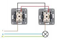
    And now the question. How to connect it to ospel as connectors? I found several schemes of this type:  Connecting Stair Connectors with Two Live Wires: Electrician Assistance for Ospel AS
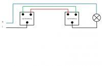
    and according to them it looks like that before connecting only in one box there should be one live wire, not two. Is this done according to some other pattern?
  • ADVERTISEMENT
  • #2 16576425
    WędkarzStoLica
    Level 31  
    jac22 wrote:
    according to them, it looks like that before connecting in only one box should be one live wire, not two.
    It has to be this way, the scheme is good.
  • #3 16576482
    marianm68
    Level 17  
    On the blue wire (if it is the equivalent of the blue one in the figure) in the bottom box the "test tube" should not show voltage (N wire - "zero"). If it shows (but weaker), I suspect that there is a break on this wire somewhere before the bottom box, and on the section of the wire (from break to can) there is "excited" voltage from the phase wire running in parallel. Because I assume that it's about the "power" side - fuses and not the connection between the boxes for the switches.
    Check in the cans that you have twisted wires properly. Have you drilled around the cables because maybe the cable under the plaster was damaged?
    The test tube can show voltage on unconnected wires ("hanging in the air") if they run on wires with a "phase" - that's the charm of this tool.

    But if, as you wrote, you have three wires in the boxes, most likely they are wires running between the switches.
    My friend jac22 you have attached a drawing / diagram with a question about its correctness: the drawing is correct. But on the diagram you have four colors (five wires)!
    If you have three wires in the boxes under the switches (you wrote about three), all you have to do is assign the appropriate wires from the boxes to the colors of the wires in the diagram. The blue wire from the diagram was most likely located outside of the boxes.
    I would bet: the brown wire is black in the drawing, the blue and yellow-green wires are green and red in the drawing.
    But these are only my guesses!
    No joke with the flow. If you are unsure, refrain from connecting to the electrician's return.
  • ADVERTISEMENT
  • #4 16576577
    polaklbn
    Level 24  
    marianm68 wrote:
    On the blue bottom, the "test tube" should not show voltage (N conductor - "zero"). If it shows (but weaker), I suspect that there is a break on this wire somewhere before the bottom box, and on the section of the wire (from break to can) there is "excited" voltage from the phase wire running in parallel. Because I assume that it's about the "power" side - fuses and not the connection between the boxes for the switches.
    Check in the cans that you have twisted wires properly. Have you drilled around the cables because maybe the cable under the plaster was damaged?


    If this is a new installation, zero is not allowed.
    Neon lamp is good to check if there is something, next to the stairs is stupid because of the phenomenon of induction.

    Buddy, if it's done like most staircases by pseudo-electrics, connect the brown wires to the L terminals, while the blue and green-yellow ones to the outputs.
  • ADVERTISEMENT
  • #5 16576763
    marek-1983
    Level 17  
    The electrician spoke. Think why this is happening and what rules the market
  • #6 16577860
    polaklbn
    Level 24  
    marek-1983 wrote:
    The electrician spoke. Think why this is happening and what rules the market

    You probably refer to my statement about pseudo-optics. The market is ruled by supermarkets, because every self-respecting wholesaler has a gas color scheme, i.e. black gray brown :)
  • ADVERTISEMENT
  • #7 16578192
    UmyslTechniczny
    Level 13  
     Connecting Stair Connectors with Two Live Wires: Electrician Assistance for Ospel AS

    Please, such a small ease. With this yellow-green wire, it is so that it goes to the housing, that is, the lighting fixture, or to the switch housing ... But to be honest, it is rarely used protective for the switch. :) Probably gentlemen, the electricians scold me, but even at the exams we didn't use it so if you don't give this wire to the switch there will be no tragedy :)
  • #8 16578278
    retrofood
    VIP Meritorious for electroda.pl
    UmyslTechniczny wrote:
    But to be honest, protective switch is rarely used. :)

    You don't say nonsense. For wireless installation, we run a three-wire cable from the switchgear directly to the switch, and then to the lamp. So where should the EP go? The standard clearly states that protective and neutral colors must not be used for any other purpose! Therefore, please do not mislead the askers!
  • #9 16578291
    UmyslTechniczny
    Level 13  
    retrofood wrote:
    UmyslTechniczny wrote:
    But to be honest, protective switch is rarely used. :)

    You don't say nonsense. For wireless installation, we run a three-wire cable from the switchgear directly to the switch, and then to the lamp. So where should the EP go? The standard clearly states that protective and neutral colors must not be used for any other purpose! Therefore, please do not mislead the askers!


    Did I write that he should pin this PE as a phase or what? I don't think so ... So I don't know what the comment is about the standard for using colors. :)
    In addition, it costs me a mistake :) Thank you.
  • #10 16579104
    jac22
    Level 7  
    Thanks. In fact, the second wire showed the voltage in the test tube because it induced it from the plus next to it. I checked it to be sure by connecting a standard light bulb (minus from the socket, plus I checked on individual wires in turn, of course, if someone read it in the future, you need to know what to do and if you don't know what's going on, it's better not to check it! because with the tide, as one of my colleagues wrote, no jokes). The voltage was only in one can and on one brown wire, which is how it should be. After connecting the connectors, approx.

    PS If the above method of checking with a light bulb according to you is not suitable in the forum please delete this post.
  • #11 16589352
    750kV
    Level 33  
    jac22 wrote:
    Thanks. In fact, the other wire showed the voltage in the test tube because it was induced by plus next to. . (...) minus from the socket, a plus ......

    There is voltage in this installation AC . There is no "plus" and "minus".
  • #12 17395169
    jaro1972
    Level 10  
    I have the same problem. How did you solve the puzzle and connected AS stair switches

Topic summary

The discussion revolves around connecting stair connectors with two live wires in an Ospel AS installation. The user describes a situation where they have multiple wires in two boxes, with varying voltage readings. Responses highlight the importance of proper wiring, indicating that the blue wire should not show voltage if it is neutral. Suggestions include checking for breaks in the wiring and ensuring correct connections according to standard practices. The conversation also touches on the use of a neon test lamp and the phenomenon of induced voltage. The user later confirms that the voltage readings were due to induction and that they successfully connected the connectors.
Summary generated by the language model.
ADVERTISEMENT