logo elektroda
logo elektroda
X
logo elektroda

33V 30A Lithium Ion Battery: Diagnosing & Repairing Damaged BMS Module SSHHD96-1-REV3, SMD Fuse

michulus 5481 17
ADVERTISEMENT
Treść została przetłumaczona polish » english Zobacz oryginalną wersję tematu
  • #1 16587625
    michulus
    Level 10  
    Hello

    I have a 33V, 30A lithium ion battery with a (most likely) damaged BMS module. It consists of 9 flat cells. The voltage on the battery cells (together) = 32V. Each of the cells individually has about 3.5V. For some reason, the BMS cuts them off and won't let the battery charge.

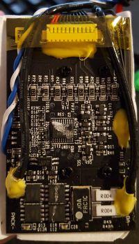
    BMS model: SSHHD96-1-REV3
    BMS dimensions: 65x40mm

    (photo attached)

    Initial measurements:

    - charger voltage at PACK- and (+) battery terminal = 42V (without 1.6V charger)
    - voltage between (+) battery and BA- = 32V
    - all voltages from the cells go to the BMS (resistors R37 to R71)
    - Low-impedance resistors (R49 and R49A) look good (32V)
    - element (F1) marked FRC1C 30A has no voltages.
    Does anyone know what this item is? I guess it's an SMD fuse, but I don't find anything specific under those markings.

    Could someone please answer the following questions for me:

    1. Is it possible to somehow diagnose and repair a damaged element in such a small BMS, I would ask for any tips for further diagnosis?

    2. What is the replacement for this BMS (PCB dimensions 65x40mm are critical)?

    33V 30A Lithium Ion Battery: Diagnosing & Repairing Damaged BMS Module SSHHD96-1-REV3, SMD Fuse
  • ADVERTISEMENT
  • #3 16587769
    michulus
    Level 10  
    F1 looks operational. I scraped off some varnish and at its output and input (T1 and T3 according to the application) I have 32V.

    Where else to look for damage?

    Added after 3 [hours] 8 [minutes]:

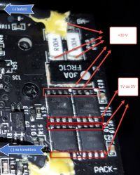
    I measured the area of these rectangular TPH4R008NH MOSFETs.
    Tensions as in the picture attached

    Feet (1-4) on Q1A and Q12 = 30V to 31V
    Feet (5-4) on Q1A and Q12 = voltage dropping from about 3V to 1V

    Feet (1-4) on Q13 and Q13A = voltage dropping from approximately 3V to 1V
    Feet (5-4) on Q13 and Q13A = voltage dropping from approximately 3V to 1V

    33V 30A Lithium Ion Battery: Diagnosing & Repairing Damaged BMS Module SSHHD96-1-REV3, SMD Fuse

    Leads of TPH4R008NH according to the application

    1, 2, 3: Source
    4: Gate
    5, 6, 7, 8: Drain

    33V 30A Lithium Ion Battery: Diagnosing & Repairing Damaged BMS Module SSHHD96-1-REV3, SMD Fuse


    Observations and measurements:

    1. It seems suspicious to me that there is about 30V on the gates (pin 4) on Q1A and Q12.

    2. After connecting the battery cells and checking the paths, it turns out that there are some significant resistances (depends on how to apply the meter probes) between the Q1A and Q12 feet. There is no breakthrough between the gate and drain and entry. I guess Q1A and Q12 might be okay.

    3. For Q13 and Q13A, in which way not to measure, it turns out that there is a breakdown between the input and the drain (
  • ADVERTISEMENT
  • #5 16588305
    satanistik
    Level 27  
    BMS circuits are not that simple - You have to look at the IC on this board, sometimes it's a dedicated chip with a built-in processor and memory. After a failure, the processor can lock permanently or requires a reset.
  • #6 16588551
    michulus
    Level 10  
    wojtek 9007 wrote:
    Please double check the FRC1C protection .....


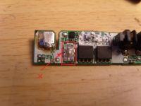
    I checked the voltage and resistance on FRC1C again.

    Measurements according to the markings of the terminals in the picture in the attachment.

    33V 30A Lithium Ion Battery: Diagnosing & Repairing Damaged BMS Module SSHHD96-1-REV3, SMD Fuse

    1. Battery connected to bms, measurement with respect to (+) on the battery
    T1 = 31.96V
    T3 = 31.38V
    T4 = 0V
    T2 = 0V

    2. Battery connected to bms, measurement between leads FRC1C

    T1T2 = 31.38V
    T1T3 = 0V
    T1T4 = 31.38V

    T2T1 = - 31.38V
    T2T3 = - 31.95V
    T2T4 = 0V

    T3T1 = 0V
    T3T2 = 31.95V
    T3T4 = 31.95V

    T4T1 = 31.37V
    T4T2 = 0V
    T4T3 = - 31.95V

    3. Battery disconnected from bms, measurement of resistance between pins of FRC1C

    T1T2 break
    T1T3 = 2.2 MOhm
    T1T4 break

    T2T3 break
    T2T4 = 51 Ohm

    T3T4 break

    I have no ideas what else I can check without desoldering.
    Please give me further guidance.
  • Helpful post
    #7 16588584
    wojtek 9007
    Level 40  
    Hello - battery disconnected, resistance measurement between leads;
    Should ;
    T1 T2 = 1.0 -2.5 m?
    T2 T3 = 1.0-2.5m?
    T1 T3 ? 2-5 m?
    These are the fuse pins of the fuse.
    Whereas T2 T4 (heater)
  • #8 16589236
    michulus
    Level 10  
    wojtek 9007 wrote:

    ...
    Should ;
    T1 T2 = 1.0 -2.5 m?
    T2 T3 = 1.0-2.5m?
    T1 T3 ? 2-5 m?
    These are the fuse pins of the fuse.
    Whereas T2 T4 (heater)


    Unfortunately, I do not have this FRC1C.

    1. Can I replace it with SMD fuses?
    As I understand it would be 1x30A for T1 T2 and 1x30A for T2 T3.

    2. Can a thermal fuse like FRC1C be soldered like SMD, or is it damaged due to the soldering temperature?
  • ADVERTISEMENT
  • #9 16589329
    satanistik
    Level 27  
    You have to check if the processor does not expose voltage to the radiator, if so, it will also burn after soldering the new one. It is a controlled fuse that allows the driver to "commit suicide", this is often stored in memory.
  • #10 16589410
    wojtek 9007
    Level 40  
    Hello - please gently remove the outside with a knife or a thin screwdriver
    this protection housing (FRC1C).
    This is what it looks like on the laptop battery protection plates;

    Added after 42 [seconds]:

    33V 30A Lithium Ion Battery: Diagnosing & Repairing Damaged BMS Module SSHHD96-1-REV3, SMD Fuse
  • #11 16589474
    michulus
    Level 10  
    Before I start dismantling, I would like to ask you something. I apologize for the (maybe) stupid question but I want to make sure that I got the (peasant) sense of the derivation of this FRC1C correctly. Could someone please confirm or improve my description

    T1 = (before the bepiecznik) i.e. battery voltage input
    T2 = (-) relative to processor logic
    T3 = (after the bepiecznik) that is the voltage output from the battery
    T4 = (+) voltage across the heater (if given by logic)
  • ADVERTISEMENT
  • #13 16589657
    michulus
    Level 10  
    wojtek 9007 wrote:
    Maybe it will help, figs 31 and 32
    http://ep.com.pl/artykuly/10299-Akumulatory_litowe.html


    Fig. 31 shows a 3 lead fuse and the FRC1C has 4 leads.
    If possible, I would ask more specifically what and how on which FRC1C foot.

    In my understanding, T2 and T4 are power to the heater and T1 and T3 are a fuse (2x in series). I would write everything as below:

    T1 = (before the bepiecznik) i.e. battery voltage input
    T2 = (-) relative to processor logic
    T3 = (after the bepiecznik) that is the voltage output from the battery
    T4 = (+) voltage across the heater (if given by logic)

    I would ask for this description to be corrected if I mixed up something.
  • #14 16589796
    wojtek 9007
    Level 40  
    Please gently pull off the outer case of FRC1C or write a detailed description
    what she looks like.
  • #15 16589879
    michulus
    Level 10  
    wojtek 9007 wrote:
    Please gently pull off the outer case of FRC1C or write a detailed description
    what she looks like.


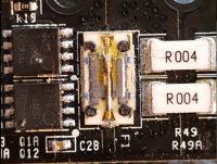
    cover removed

    33V 30A Lithium Ion Battery: Diagnosing & Repairing Damaged BMS Module SSHHD96-1-REV3, SMD Fuse


    I desoldered and checked 4 Mosfets that I had suspicions about earlier. They are all ok.


    Added after 8 [hours] 59 [minutes]:

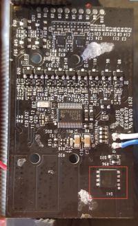
    I think I found the first damaged element. On the opposite side of the BMS, the one (as I guess) responsible for charging the battery. The MOSFET AON6576 is defective. It had a breakdown between the drain and the source and no insulation to the gate.
    It seems that it also stuck to the previously soldered Toshiba Mosfets.


    I would like to suggest what to replace it with:
    (it must be a MOSFET in the FDN8 5x6 housing)

    AON6576 datasheet ( Link )


    33V 30A Lithium Ion Battery: Diagnosing & Repairing Damaged BMS Module SSHHD96-1-REV3, SMD Fuse
  • #17 16593852
    michulus
    Level 10  
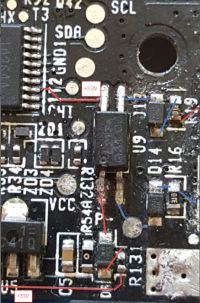
    I would like to ask about the connections (below picture and attachments) showing the U9 optocoupler and its surroundings.
    The U9 markings are L217 G31 C. It comes out to me from the path analysis that U9 is a circuit responsible for switchgear and sources on Mosfet transistors.


    Description:

    U9 foot # 4 - it receives + 3.3V from the microcontroller (from foot 13)

    U9 pin # 3 - output to the D13 diode and the Q1A, Q12 mosfet gates, and through the R19 resistor, to their sources.

    U9 foot # 2 - output to the D14 diode (for the diode, the connection to the PACK- terminal), then to the Q13, Q13A mosfet gates. Through the resistor R16, at their source.

    U9 kickstand # 1 - here's a strange thing! As I understand it, there should be voltage (+) on the foot # 1, but there is a R131 resistor (10K) and a DR diode on the way. The diode looks like it is soldered in the opposite way! The designation of the DR LED is WW N3. Checked (without desoldering) shows 723 mV in forward direction. A voltage of a few mV between the DR diode and pin 1 U9.

    Questions:

    1. Is my analysis correct and in fact the DR is soldered inversely at the factory?

    2. How to decode WW N3 markings, maybe it's not an ordinary LED but some SMD Zener or something like that. How to identify it?

    3. Is U9 labeled L217 G31 C surely a classic 217 optocoupler?


    33V 30A Lithium Ion Battery: Diagnosing & Repairing Damaged BMS Module SSHHD96-1-REV3, SMD Fuse
  • #18 17388544
    alain vicet
    Level 1  
    @michulus Hello,

    I have 10 batteries for bikes with the same BMS: SSHHD96 rev03

    Were you able to repair your card?

    I also need some information on this map, especially about the functions of the white and blue wires. Do you know the functions of these 2 wires?

    thank you

Topic summary

A user is troubleshooting a 33V, 30A lithium-ion battery with a suspected damaged BMS module (model SSHHD96-1-REV3). The battery consists of 9 cells, each showing approximately 3.5V, but the BMS is preventing charging despite a charger voltage of 42V at the terminals. Initial checks indicate that the SMD fuse (FRC1C 30A) shows no voltage, leading to inquiries about its function and potential replacement. Users discuss the possibility of diagnosing and repairing the BMS, including checking MOSFETs and the processor's role in the circuit. A defective MOSFET (AON6576) was identified, with suggestions for replacement (AON7528). The discussion also covers the functionality of various components, including an optocoupler (U9) and the implications of thermal fuses in the circuit.
Summary generated by the language model.
ADVERTISEMENT