logo elektroda
logo elektroda
X
logo elektroda

Connecting & Charging 3S2P 18650 Cell Pack with HX-3S-FL25A-A BMS: Balancer, Overload & Discharge

Dawek1997 43743 22
ADVERTISEMENT
Treść została przetłumaczona polish » english Zobacz oryginalną wersję tematu
  • #1 17269223
    Dawek1997
    Level 6  
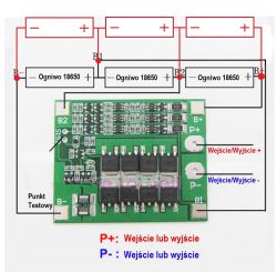
    Hello, I have a 3s2P cell package and I have a question if it can be loaded with this module. In the seller's drawing, the 3s1P package is drawn, whether it will load properly when the links are connected in parallel. Is this module enough to charge such a package and protect it against discharging and overcharging, should you connect something else?

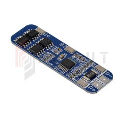
    Connecting & Charging 3S2P 18650 Cell Pack with HX-3S-FL25A-A BMS: Balancer, Overload & Discharge


    Product description:

    Model: HX-3S-FL25A-A
    Overload protection: 4.25 ~ 4.35V ? 0.05V
    Discharge protection: 2.3 ~ 3.0V ? 0.05V
    Maximum current: 0 ~ 25A
    Protection against turning: yes
    The system is used to protect the packet from overcharging and discharging. Additionally, it contains a balancer that balances the voltage in the packets during charging.
  • ADVERTISEMENT
  • Helpful post
    #2 17269322
    Wojtek(KeFir)
    Level 42  
    No. This has two functions. Balancer - spreads the load equally on the links. And the OVP UVP OCP fuse. Nothing more. There is no charging logic, no temperature measurement, no charge time analysis, no current ramp.
  • Helpful post
    #3 17269990
    krzysiek_krm
    Level 40  
    Hello,
    sellers call these tiles: a safety system with a balancing function.
    In my opinion, you can use your plate only as a protection system type "hardware secondary protection" but even this function is not quite sure.
    First of all - security.
    Vendors delightfully give detection voltages OVC = 4.25 - 4.35 V and OVD = 2.3 - 3.0 V. This is some mindless tracing of the first page catalog data of the voltage detection system, actually these voltages are from a certain range, but the end user has no possibility of adjusting them . The systems are manufactured in a number of versions that have different combinations of these voltages pre-set. You should read the markings of the detection systems on your board and check in the catalog data whether by accident the current combination of detection voltages does not match your links like the ox to the carriage.
    Second - balancing.
    From the available here and there descriptions of this board, "balancing" uses hardware 4.2 V detectors, which short-circuit the cells with 100 ? resistors, giving a dizzying 42 mA balancing current, i.e. "balancing" is formally but it is not there. Such a balancing current is great for "low power" systems, but the 25 A current limit suggests that this is probably not the case.
    You should therefore buy some decent charger with reliable balancing.
    It would also not have been necessary to equip the battery with signaling detectors and possibly disconnecting the load at a cell voltage higher than the final cut-off voltage, notorious disconnection by the protection system will cause rapid deterioration of the cells and shorten their life time.

    greetings
  • #4 17270451
    Dawek1997
    Level 6  
    The electronics have been taking care of the amateur for some time, but somehow I could not get the whole BMS, balansers. So, BMS, as I understand it, I can only use to protect cells from discharging, overloading, and before downloading too much electricity, and the balancer to load each cell evenly. The purpose of this package, welded together links, will be to place it permanently in the middle of the portable speaker. Therefore, a similar BMS circuit with a balancer only for a smaller current because I definitely do not need 25A, can be mounted in the middle of my device, connecting to this charger and lead from it a connector to connect an external 12.6V power supply with a current limit of 8A ? Would that be more correct? (https://diolut.pl/ladowarka-3s-8a-12-6v-bmspms-li-ion-do-ogniw-18650-p-22104.html?gclid=Cj0KCQjwu_jYBRD8ARIsAC3EGCLQkGIH9qUGXgbd_UvJOPOp4DyHe_33R4chYwgt1CUiU9PjaDC6FGkaAnJJEALw_wcB)
    Connecting & Charging 3S2P 18650 Cell Pack with HX-3S-FL25A-A BMS: Balancer, Overload & Discharge

    Added after 2 [minutes]:

    Is this only BMS and not a charger and I can not charge it? I'm already confused :)
  • Helpful post
    #5 17270486
    Wojtek(KeFir)
    Level 42  
    No, only BMS.

    Here's a bit to read:
    https://www.richtek.com/en/Design%20Support/Technical%20Document/AN050

    An example of a scalar that has a stitched Li-ion charging program in it is LTC4007. Linear technologies generally have a whole range of charge drivers for everything. Generally, this company has very interesting and unusual scalaki. Unfortunately - to buy it in Poland is a massacre. Third World.
  • ADVERTISEMENT
  • #6 17270537
    Dawek1997
    Level 6  
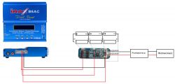
    Hmm ... So I could connect the BMS itself to the links as a protection of these cells against excessive discharging during the operation of the loudspeaker, and connect a charger such as imax for charging? Additional balancer's duplication is unnecessary because the charger has it in itself, and the balancer is only needed for charging? I connect the charger in parallel with the BMS in the loudspeaker?

    Added after 30 [seconds]:

    I apologize in advance for my curiosity :)
  • Helpful post
    #7 17270711
    Wojtek(KeFir)
    Level 42  
    The balancer is only needed when charging. You can connect a BMS that will not have a balancer in it. It will simplify the layout.
  • ADVERTISEMENT
  • #8 17270758
    Dawek1997
    Level 6  
    So it will be the correct connection? I do not bother you anymore
    Connecting & Charging 3S2P 18650 Cell Pack with HX-3S-FL25A-A BMS: Balancer, Overload & Discharge
    head as correctly.
  • #10 17270991
    Dawek1997
    Level 6  
    or from Imaxa 2 wires to BMS input pins from controlling cells?
  • #12 17271110
    Dawek1997
    Level 6  
    Wojtek(KeFir) wrote:
    No, definitely not.

    Here you have BMS without a balancer. http://allegro.pl/1-3s-bms-pcm-3-6-12-6v-10a-li-ion-zabezpieczenie-i7042675107.html

    He only measures the voltages of individual sections and analyzes them. You use the balancer from the charger.


    Wojtek(KeFir) wrote:
    No. You just did not have current connections.
    http://redberet.pl/templates/images/files/3129/powerbean-1152202406.pdf


    Mhm ... So everything is like in my schematic but I also have to lead two wires from Output BMS and also connect to Imax and it will be cacy? :)
  • ADVERTISEMENT
  • #13 17271218
    Wojtek(KeFir)
    Level 42  
    Do not Output only B + and B- with those round sockets on the left on Imax. These are the current terminals - that's how it charges the battery. This small plug only measures if everything goes well and even.
  • #14 17271242
    krzysiek_krm
    Level 40  
    The two plates HX-3S-01 found by you are only I'm afraid, however, that it may have a slightly too low OVD detection threshold, I think you should use a system (or systems) to signal the state in which the voltage any link is lower than (say) 3 V.
    Wojtek(KeFir) wrote:
    Do not Output only B + and B-

    Unfortunately, you probably are not right. From available here in the network (although slightly obscure) diagrams show that connecting to B + and B- you will connect the charger to the "bare" battery, bypassing the cut-off transistors and current resistor, ie the protection will not work, please connect to P + and P - anyway, having a physical tile you can see how connections are going.
    So from another keg, do not abuse the abbreviation BMS, it is usually a "Battery Management System" - a fairly extensive and complex system of very advanced "dominion" over the battery.
  • #15 17271278
    Wojtek(KeFir)
    Level 42  
    Well, that's right. But take a look at all modeling packages. You are just charging directly, using the built-in security device. In turn, in laptops is how you write, the battery electronics is permanent.
  • #16 17271980
    krzysiek_krm
    Level 40  
    Wojtek(KeFir) wrote:
    Well, that's right. But take a look at all modeling packages. You are just charging directly, using the built-in security device. In turn, in laptops is how you write, the battery electronics is permanent.

    To be honest, I hardly know these "buy" chargers, maybe they have such "in themselves" protections or maybe they do not. It seems to me quite unlikely, these chargers are usually quite universal, for different types of cells, so they would have to have these protection systems configured in some way, which would probably be quite complicated and rather expensive.
    Certainly they have such protection built into the software, but the use of a hardware security system is advisable. It is such a "last line of defense cells" in the situation when everything else fails: the processor will hang, the output transistor will break short, etc. It is just a certain redundancy, using a relatively simple hardware layout, for which the probability of failure is quite small, of course, this is not an impossible event, but there are no devices with 100% reliability.
  • #17 17272059
    Wojtek(KeFir)
    Level 42  
    Well, they have it. They have a processor, a program in the processor, and he controls it. You have a display, a keyboard and you set yourself.
  • Helpful post
    #18 17272087
    krzysiek_krm
    Level 40  
    Wojtek(KeFir) wrote:
    Well, they have it. They have a processor, a program in the processor, and he controls it. You have a display, a keyboard and you set yourself.

    That's what I meant. Plenty of devices have a processor in which some threshold voltages or currents are set. Some devices are completely hardware, they also have some threshold values. In the case of lithium-ion cells, which are quite "sensitive" to overcharge and excessive discharge (for explosion and ignition), additional use of "hardware secondary protection" systems has been adopted, which are quite simple and therefore highly reliable, which "in case of what "just cut off the link from the" rest of the world ": charger or load. The processor may hang, the hardware system may be damaged, so the extra protection system is simply a redundant protection.
    It's a bit like fuses here and there - you can assume that a TV, computer, washing machine or whatever manufacturer did it well - so why fuse.
  • #19 17746495
    bigdanmura
    Level 1  
    There are a number of collaterals called colloquially BMS or PCB, PCM. Most of them are security with or without a balancer. The balancer on the security allows you to control every single cell in the package. I check the control. There are protections with a charging system eg TP4056, using a built-in balancer to properly distribute and control the charging current, discharging on each cell as in powerbank packages where we can connect a typical mains power supply with a specific voltage and current to the charging. What I'm looking for - all modeler and dedicated loaders have built-in hardware and software protection allowing for professional charging with pulse current in 3 modes, setting threshold parameters of the cell, etc. If we want to charge the charger via the BMS, it's only on the B + input, B- (raw link) ) and not on P +, P-. We give all control to the charger and not the security system (mirroring). Of course, in package layouts over 1s there would have to be additional output to the charger balancer. It loads the cells through dedicated chargers while in the cell container I have a built-in PCB protection system to not damage the cells during operation. That's all :) )))

    Moderated By Madrik:

    3.1.19. Do not send messages on archive topics if it is another question, in particular other than the questioner. Because of the respect to the questioner, create your own topic. You can only add a way to solve the problem.

  • #20 17872593
    korejwo
    Level 9  
    Hello, I have a bms with a separate input for discharging and charging, but I want to connect it just under the input for discharging bypassing the charging plug. I would do everything with a cable to unload tz (charge and unload) if it is safe and possible? 10s3p package
  • #21 18387206
    szeryf3
    Level 29  
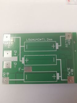
    Connecting & Charging 3S2P 18650 Cell Pack with HX-3S-FL25A-A BMS: Balancer, Overload & Discharge
    Please tell me what this contact described as "F-" is for?
  • #22 20109123
    tadek125
    Level 12  
    Hello
    Will heat up the cutlet a little

    I convert Makita 14v batteries to li-ion

    As far as I understand the connection of bms and balancer to the package of cells, e.g. 4s1p, I do not know how to connect bms and balancer to the 4s2p package.
    Should I use a separate balancer and only 1 bms for each package?
    Or maybe only one bms with a 4s balancer and then connect 2 batteries (1 from each balancer package)?
    Or maybe there are some balancers for a larger number of cells, in this case for 8 and 1 balancer?
    Or maybe it is solved differently in the original screwdrivers.

    I am asking for a hint and clarification
  • #23 20109189
    Grendel
    Level 21  
    Hello.

    In such a situation, one BMS with a 4s balancer is used, and the cells are connected by 2 in parallel.
    Such a circuit, usually only 3s2p, is used, for example, in every older laptop.

Topic summary

The discussion revolves around the use of the HX-3S-FL25A-A BMS for a 3S2P 18650 cell pack. Users express concerns about the BMS's capabilities, particularly regarding its lack of charging logic and temperature measurement. It is clarified that the BMS can provide protection against overcharging and discharging but lacks a built-in balancer for even cell charging. Users suggest using a separate charger with a built-in balancer, such as the Imax, for effective charging. The importance of redundancy in protection systems is emphasized, as well as the need to connect the charger correctly to ensure safety and functionality. The conversation also touches on the necessity of understanding the specifications of the BMS and the cells to avoid mismatches in voltage detection thresholds.
Summary generated by the language model.
ADVERTISEMENT