logo elektroda
logo elektroda
X
logo elektroda

Elektrobim with the HB-5 control panel does not open one leaf.

tino2003 7323 19
ADVERTISEMENT
Treść została przetłumaczona polish » english Zobacz oryginalną wersję tematu
  • #1 16620464
    tino2003
    Admin of GSM Group
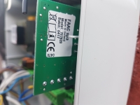
    A friend bought a set on the Allegro and asked to connect it, so from the control panel to the actuators according to the diagram from the "motor" of the control panel to the "motor" of the actuators. The jumpers in the control panel were as in the photo.
    After programming the remote control by pressing the button, one actuator closes the gate for 20 seconds because this time is set and the other does not react at all, after pressing the button for the second time, the leaf opens again and should close. the latter, as I wrote, does not react at all (the voltage from the control panel goes up to the ankle on the actuator and yet there is no reaction.
    Every day I do not deal with the assembly of gates, but I want to help the peasant and here I do not really know how, because I connected it incorrectly, or he got a faulty set from the Allegro.
    Will someone guide?
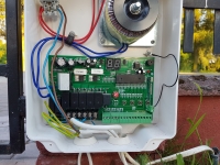
    Elektrobim with the HB-5 control panel does not open one leaf. Elektrobim with the HB-5 control panel does not open one leaf.
  • ADVERTISEMENT
  • #2 16620645
    suworow
    VIP Meritorious for electroda.pl
    Probably our gate specialists will give you more and more sensible ideas, but at least this is how to start:

    1. Are you sure that you are using the correct button on the remote control and that you programmed the remote controls properly?
    The procedure for entering the remote control is as follows:
    Press the "LEARN" button on the control unit once, the "LEARN LED" lights up.
    Then press and hold the selected button on the remote control, the "LEARN" LED will blink.
    The selected button controls two leaves simultaneously.
    Press the "LEARN" button on the control unit twice, the "LEARN LED" lights up.
    Then press and hold the second selected button on the remote control, the "LEARN LED" will blink.
    The second selected button controls one leaf (connected to the Motor 1 input).

    2. swapping the actuators.
    3. The gate works without pics, so the photocell input must be shorted to ground. Otherwise, it should not close.
    4. try to hand-start the drive with the "button 1" or "button 2" contacts. I do not know, I have not dealt with this invention, so I will not say whether both wings are started with button 2 or, for example, you have to press button 1 and button 2 at the same time. I dare to suspect that button 1 starts 1 wing, so it is used for work the control panel in a system with one leaf / sliding gate drive.
    5. Tell a friend that you use earth cables for such purposes and that it is not always a good idea to run the system without pics ;)
    best regards
  • #3 16620910
    tino2003
    Admin of GSM Group
    suworow wrote:
    1. Are you sure that you are using the correct button on the remote control and that you programmed the remote controls properly?


    I programmed two remote controls myself, it is done as you wrote, but the question is whether the same button opens and closes the gate? From the description it looks like it should be so and it only works in one direction each time.

    suworow wrote:
    2. swapping the actuators.


    Today I will try to rule out damage to one of the actuators.

    About 34V appears on the actuator that does not respond after switching on the relay, and yet no reaction.
  • ADVERTISEMENT
  • #4 16620961
    suworow
    VIP Meritorious for electroda.pl
    tino2003 wrote:
    I programmed two remote controls myself, it is done as you wrote, but the question is whether the same button opens and closes the gate? From the description it looks like it should be so and it only works in one direction each time.
    I don't know this "hardware" but most of the gates do. Anyway, start by closing the line of photocells - as I already wrote about. If I can see the jumper between pin 8 and 9 correctly.
    tino2003 wrote:
    About 34V appears on the actuator that does not respond after switching on the relay, and yet no reaction.

    Right.

    tino2003 wrote:
    suworow wrote:
    2. swapping the actuators.

    Today I will try to rule out damage to one of the actuators.

    Maybe it's enough if you measure and compare the resistance of both actuators ... Maybe there is no transition. 34V seems a lot compared to the 24 nominal ...
    I am sending greeting and I wish you good luck
  • ADVERTISEMENT
  • #5 16621043
    tino2003
    Admin of GSM Group
    suworow wrote:
    If I can see the jumper between pin 8 and 9 correctly.


    This could be the heart of the matter.
    I'll check in the evening and let you know. :)
  • #6 16621471
    kotbury
    Gantry automation specialist
    Test the system of limit switches in the actuator - these are microswitches with serial diodes - maybe the closing polarity has no transition

    And in general, this control panel is adapted to the limit switches connected to it and not cutting off the power supply of the actuator. So the best solution would be to connect the existing limit switches with additional cables to the control panel, because if you leave it as it is, there will be circuses (such as the need to press the remote control twice, unsynchronizing the wings, etc. There is a whole topic about prosthesing the shortcomings of this set).

    And powering these Chinese with a voltage of over 30V is the norm and a way to start these snails. And apparently they withstand it ...
  • #7 16621546
    tino2003
    Admin of GSM Group
    I am a step further, namely there was no jumper for the photocells. One actuator is already working back and forth and the fact that you have to click twice is not a problem.

    Now just check why the second one does not work despite adequate power supply.
  • #8 16622003
    lamerb
    Level 25  
    Since there is voltage to the actuator connection block, either the motor is broken (connect for a short time to check) or the problem is in the limit microswitches.
  • #9 16636523
    tino2003
    Admin of GSM Group
    lamerb wrote:
    Since there is voltage to the actuator terminal block, then the motor is knocked out


    It turned out that the new actuator was damaged, today I got it in working order, but that's not the end of the problems. :D

    The opening time is set to 45s and during this time one leaf closes completely and the other is pulled up halfway (the limit switch has been bypassed so it does not disconnect). The conclusion is that one of the motors is slower or another reason that I cannot think of.

    I gave the soft start for a minimum of 1s.

    In general, I increased the time to 57s and during this time the slower actuator will come to the end and on the second I limited it with a limit switch, but it probably should not be the case.
  • #10 16637779
    kotbury
    Gantry automation specialist
    First, check the actuator force settings - maybe it is so low on the coax that it slows down.
    If not - replace the actuators - i.e. connecting them to the control panel - in places - if the slow work "goes" to the other actuator - you have a sloppy control unit (it has a transistor control of power and speed of the actuators - maybe something in this system), and if not - slow it will still be free - something with an actuator again - look at the nominal voltage at the beginning - these Jacks were produced for several different supply voltages and maybe you got a different one than the first one.
  • #11 16637801
    tino2003
    Admin of GSM Group
    The force was set the same, I swapped places and it turned out that now the other one opens slower. So I connected both actuators to one output in the control panel and it somehow started to work.
    You can also set the overload somehow if this is the force parameter, I ask because regardless of the settings, it is still the same.

    I would never recommend this type of actuator to anyone. A friend who bought it already knows what mistake he made. :D
  • #12 16637935
    kotbury
    Gantry automation specialist
    In fact, reading the manual carefully, the said "force" is an overload and there is no separate speed setting. It turns out that the damaged output works on slowing all the time. You can repair it yourself (unless the processor is sitting) but try to use the warranty first.
    Generally speaking, selling this control panel together with these PowerJacks is a misunderstanding (apart from the questionable quality of them). It is rigidly adapted to work with actuators equipped with separate, non-cut-off limit switches, any other application is a prosthesis. The actuators can be converted, but this is not why you buy a ready-made set to start with a soldering iron right away ...
  • #13 16645392
    tino2003
    Admin of GSM Group
    The whole set will be returned because it is one big disaster, the buyer will talk to the seller to return it and pay extra and take FAAC 414.
    Therefore, I have a question because the FAAC set includes photocells, are they necessary for the set to work or not to be connected. There are no cables exiting the photocells, and it is not really how to run these cables.
  • ADVERTISEMENT
  • #14 16645548
    suworow
    VIP Meritorious for electroda.pl
    You can not connect the photos - although this is not the best idea, and on the control panel, close the line with a jumper you already know ;)
    Take your time with this order so much. A 230V drive to work and yes, 3 wires are enough, but a protective one would also be useful ;)
    best regards


    ps, I don't even pick on that "wiring" is white
  • #15 16649016
    tino2003
    Admin of GSM Group
    This jumper to bypass the photocells in the control panel from a set of faac 414 455D between what pins should it be?
    Simple timing programming is enough?
    There is a solid stop on the gate closure, but there is nothing on the opening - could it be?
    Enrolling the keyfob, as they write, press the button on the control panel for 1 second and then on the keyfob for a few seconds, then the LEDs in the control panel stop blinking and supposedly should be. Yes?
    Should you pay attention to something, is the manual sufficient?
  • #16 16649074
    kotbury
    Gantry automation specialist
    1. Jumper between 12,13 and 19, in addition between 11 and 14
    2. No. If you don't have encoders and limit switches, miracles will come out. Use full programming.
    3. Maybe, but be aware that if you use time-lenses on the opening without bumps, they are so imprecise that once the gate stops well, and at other times it will go further, and if you have something valuable (a flower bed of orchids behind the wing, for example), you can stop having . It is acceptable that you choose the mounting dimensions of the actuator so that the maximum slide of the actuators corresponds to the extreme open positions of the wings. It is not very healthy for the actuator (it should hit the extreme positions of the piston, but nothing should happen to it).
    4. Assigning keyfobs is done using the receiver's buttons. You do not press anything on the control panel. And what and how to press it depends on the type of receiver you have plugged into the disc. Again, the receiver's instruction is sufficient.
  • #17 16649105
    tino2003
    Admin of GSM Group
    Thanks for the information, then he will have to give himself bumpers for the opening.
  • #18 16655220
    tino2003
    Admin of GSM Group
    kotbury wrote:
    1. Jumper between 12,13 and 19, in addition between 11 and 14


    The jumpers are made as you wrote, the gate is closed and then I enter the time learning option, I press the button, the LCD starts flashing and the gate opens, when it reaches the stops, it should be programmed that the desired opening has been obtained and here the problem is because I do not know what to press then because the engines hum all the time.

    I also do not know how to program the remotes because there are no instructions in Polish. It is possible that somehow I managed to program one remote control because when I press button 1 on it, the LED on the receiver will flash and you can hear the operation of the relay.

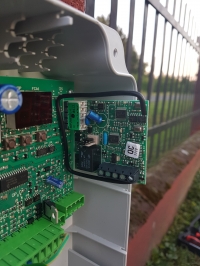
    A few photos of what it looks like now:

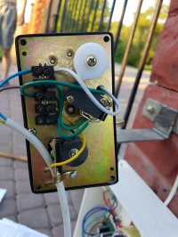
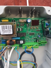
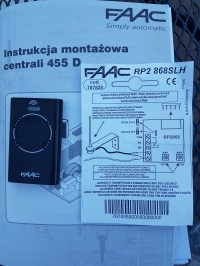
    Elektrobim with the HB-5 control panel does not open one leaf. Elektrobim with the HB-5 control panel does not open one leaf. Elektrobim with the HB-5 control panel does not open one leaf. Elektrobim with the HB-5 control panel does not open one leaf.
  • #19 16655667
    kotbury
    Gantry automation specialist
    Quote:
    When it reaches the fenders, it should be programmed that the desired opening has been obtained and here is the problem because I do not know what to press then because the engines are buzzing all the time.

    Nothing will be programmed (it would set itself - and not quite - if you had encoders) - firstly, use complete (full) programming, not simple, secondly, it's best if you wrote the remotes correctly first - the slowdown and stop points are set most conveniently button on the remote control (see manual). After completing the time setting procedure, run the menu through the In function (end of settings) until the display of the gate status reappears - otherwise the operator will not remember the settings.
    And the radio - according to your instructions - press and hold the remote control button, then press and hold the channel 1 button on the radio for 1 second.
    It is true that the stairs begin and the manual is incomplete - because in this system the first coded remote control is the "master" remote - and the full adding procedure looks like this: http://www.pilotydobram.pl/files/243/faac-xt2-xt4-868slhlr -instruction-programming.pdf and you can either add the following remotes to the receiver in the same way as master remotes, or the next ones (also according to the above-mentioned description below) are cloned from the master - and then those are cloned with slave remotes - which cannot be cloned further.
    PS - judging by clicking the relay - the remote control has been added to channel 2 of the receiver (channel 1 - led out to the pins - is on the transistor and does not click), which, firstly, is not led to the pins but only the screws, and secondly - after connecting the cables to the connector The switchboard is usually used to activate the wicket function. The diode at SW2 is probably flashing.
  • #20 16656144
    tino2003
    Admin of GSM Group
    kotbury wrote:
    The diode at SW2 is probably flashing.


    This was the reason the remote control was not working. I just assigned it to SW2 instead of SW1.
    The drive is now working properly.
    Thanks for the hints.

Topic summary

The discussion revolves around troubleshooting an Elektrobim gate system with an HB-5 control panel, where one actuator fails to respond while the other operates correctly. Initial steps included verifying remote control programming and ensuring proper connections, including jumpers for photocells. Users suggested testing the actuators, checking limit switches, and ensuring correct voltage levels. After identifying a faulty actuator, the user managed to get one actuator working but faced synchronization issues, leading to adjustments in timing settings. Ultimately, the user resolved the remote control programming issue, allowing the system to function properly.
Summary generated by the language model.
ADVERTISEMENT