logo elektroda
logo elektroda
X
logo elektroda

MHOUSE CL2SK Gate Control Panel Not Opening: ECSbus Flashing, Relay Clicks, Repair Tips

Daniel Wolski 19653 25
ADVERTISEMENT
Treść została przetłumaczona polish » english Zobacz oryginalną wersję tematu
  • #1 16893971
    Daniel Wolski
    Level 1  
    Hi,
    I wanted to fix the Mhouse cl2sk gate control panel. When voltage is applied the relay(s) click but the gate does not open and the "ECSbus" light starts flashing rapidly. Can anyone help in the form of repairing the control panel?
  • ADVERTISEMENT
  • #2 16894035
    Anonymous
    Anonymous  
  • ADVERTISEMENT
  • #3 16908492
    pppooo
    Level 17  
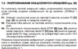
    First of all, you need to search for bus devices if you do not have them plugged in now (ecbus plug is disconnected)

    MHOUSE CL2SK Gate Control Panel Not Opening: ECSbus Flashing, Relay Clicks, Repair Tips
  • #4 16921859
    Grzegorz-z78
    Level 1  
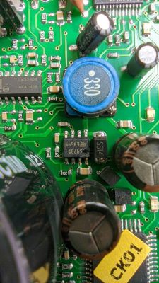
    Hello. I have a problem with the same switchboard. My dog got on it, bit the cables (already repaired) but one element marked with a black circle next to the antenna socket crumbled, it is probably a resistor connecting the antenna screen to ground. I need its value, you can't see any inscription in the photo, but you can measure it with a meter. Thanks in advance.
  • #5 16924123
    Moris10
    Level 16  
    Hello
    I have a similar problem with this driver. The control panel broke down beautifully in the network (interphase went to the power supply). In addition to blown fuses, it also damaged the tip127 transistor at the bridge. After I mention it, the angle setting still doesn't work. The control panel detects the device, when I turn on the angle setting, you can hear the relays turn on for a moment, but the wings do not even vibrate. It turns out that this transistor is still burned after such a procedure.
    Anyone have any idea what could be wrong with this switchboard?
  • #6 17261702
    Krystian Ferfecki
    Level 2  
    Moris10 wrote:
    Hello
    I have a similar problem with this driver. The control panel broke down beautifully in the network (interphase went to the power supply). In addition to blown fuses, it also damaged the tip127 transistor at the bridge. After I mention it, the angle setting still doesn't work. The control panel detects the device, when I turn on the angle setting, you can hear the relays turn on for a moment, but the wings do not even vibrate. It turns out that this transistor is still burned after such a procedure.
    Anyone have any idea what could be wrong with this switchboard?

    Hello

    You dealt with this switchboard because I have the same reason and I don't know what to catch.
    best regards

    Added after 5 [minutes]:

    Grzegorz-z78 wrote:
    Hello. I have a problem with the same switchboard. My dog got on it, bit the cables (already repaired) but one element marked with a black circle next to the antenna socket crumbled, it is probably a resistor connecting the antenna screen to ground. I need its value, you can't see any inscription in the photo, but you can measure it with a meter. Thanks in advance.


    This is an smd capacitor, but I do not know what value it is, and the 2 red ball is the L5973D system
  • #7 17746792
    Moris10
    Level 16  
    For me, the topic fell, I bought a new one. I even gave to the electronics, but he didn't take the glove.
  • #8 20397881
    michal54_87
    Level 17  
    Hello, I am repairing these switchboards, if something is called 697444055
  • #9 20645652
    keszok
    Level 2  
    Does anyone know what the part number for this IC is? MHOUSE CL2SK Gate Control Panel Not Opening: ECSbus Flashing, Relay Clicks, Repair Tips
  • #10 20646087
    michal54_87
    Level 17  
    L5973D breaks down most often, it is difficult to replace it because it has a terma falling underneath. And 4 others are damaged in the process. If it is damaged, I replace 5 systems in total.
  • ADVERTISEMENT
  • #11 20657039
    keszok
    Level 2  

    Does anyone know if it is possible to replace the NICE MCA2 switchboard?
  • ADVERTISEMENT
  • #12 20657418
    kotbury
    Gantry automation specialist

    Sure you can. And isn't it better to use a native switchboard that is 2 times cheaper - for example Woster RSB2 S?
  • #13 20657460
    keszok
    Level 2  
    Maybe it's different - what switch do you recommend instead, a relatively simple one without additional modifications and combinations that will work with actuators without limit switches? MHOUSE CL2SK Gate Control Panel Not Opening: ECSbus Flashing, Relay Clicks, Repair Tips
  • #14 20657713
    kotbury
    Gantry automation specialist
    Post above.
    But some combinations will always be because the terminals are arranged differently than in the original cl2s and you will have to read the instructions.
  • #15 20678954
    rysiekb666
    Level 1  

    Hello. I have a problem with cl2sk, the radio works, it can be programmed, it does not start the actuators and the lamp, the diodes in the photocells do not light up, I disconnected them and started device recognition, then nothing. I replaced the L5973D, still nothing. LED on ECSbus flashes 11 times, pause, then 11 times, no error code found.
    Is it salvageable? Regards
  • #16 20685090
    michal54_87
    Level 17  

    Yes, it is salvageable, please contact me on 697444055.
  • #17 20740666
    Marko121
    Level 17  
    Hello, I am repairing such a control panel and I came to the conclusion that if the L5973D fails, I also need to replace the TIP127 (it supplies power to the L5973D and most often it is also failed) between the ULN2004 system and the large capacitor and the main bridge, then I must replace 2 pieces of HEF4050BT near the micro switches and probably LM324 (in the middle of the board) and CD4504BM, all these systems are powered by the L5973D converter and if it fails, the power supply to the mentioned systems is 30V, which destroys them.
    I replaced everything except LM324 and cd4504 because it seems to me that they survived, although I still have to buy and replace cd4504 because the board started to respond to the remote control but the BUS diode flashes 11 times and I don't know if something is still damaged or it is the result of components not connected because the board I have it on the table and the gate is 10 km away.
    Does anyone know what error 11 flashed by the ECBUS diode means?
  • #18 20754232
    Fidelis
    Level 16  
    Marko121 wrote:
    I am repairing just such a control panel


    So how did you manage to repair the switchboard?
  • #19 20754905
    Marko121
    Level 17  
    I replaced all the above-mentioned systems and on the table it worked properly, the bus diode flashed systematically every second after the remote control, I could hear the relays clicking, but since there was no load connected to the actuator outputs, after the remote control the diode started flashing 11 times, so I concluded that it was the lack of actuators that caused these 11 flashes. I went to the gate and installed it, and after the first time using the remote control, there was gray smoke and all the systems mentioned above went up in smoke again. I have no idea what causes this fault, after all, the actuators are controlled by relays and not from the voltage produced by the L5973D converter. So the fight starts again
  • #20 20755027
    Fidelis
    Level 16  
    Marko121 wrote:
    grey smoke


    Oh, that's sad. I focused on replacing electrolytes. However, I checked/measured all the elements that could be checked with a tester: transistors, capacitors, diodes. All results are normal (TIP127, which you write about - also) and the control unit does not work as it should: sometimes it opens, sometimes it does not open, another time the gate opened by itself, etc.
  • #21 21085546
    ZgredekLCD
    Level 8  
    Hey,
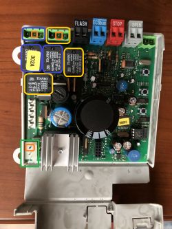
    I also have a problem with the controller, I would like to ask about a very basic thing, it is about the power connector of the board (marked in green), why are there 3 pins? The one marked in orange is ground, and the other two are from what? I understand as if there were two + / - pins, but what is the third one responsible for?
    It is also interesting that ~23V AC goes in there.
    Generally I have the problem that one side of the gate opens and the other does not (no voltage on the output connector), surely it is not the gate motor, because I swapped the connectors and then the other motor is activated.
    Controller board with highlighted power connector and components. .
  • #22 21085861
    Fidelis
    Level 16  
    ZgredekLCD wrote:
    I understand as if there were two + / - pins, but what is the third one responsible for?

    Protective?
  • #23 21091272
    ZgredekLCD
    Level 8  

    Fidelis wrote:
    ZgredekLCD wrote:
    I understand as if there were two + / - pins, but what is the third one responsible for?


    Protective?
    Thanks! I didn't have a power supply at hand, because that's what I would have deduced for myself with a multimeter :)

    Generally it's similar to @Marko121 ECSbus blinks 11 times (if I specify OPEN, otherwise it blinks normally) . One side of the gate works and the other does not. I remember looking at how much was going to the actuator it was ~30V so I'm starting to suspect L5973D, however looking at it it doesn't look like it's burnt out. Has anyone had this happen

    Btw. Can I test it like this without the actuators connected? Will it then throw this error? Generally in my case the whole thing is totally simplified, because I have neither detectors under ECSbus, nor lights. Only remote controls + control panel + actuators.

    EDIT.
    I soldered new relays (a little prophylactic, I tested the old ones and they are still ok), patient no change, giving the OPEN signal on connector 2 (next to ECSbus) there is a voltage of 30-31V [a little much], but only for 1-1.5s[/tr].
  • #24 21184042
    Jacck
    Level 26  
    I have a control panel after a surge. After replacing TIP127, L5973D, HEF4050BT and CD4504BM the control unit came to life but only opens one gate leaf.
    Following the paths I found that the HF3FA relays are controlled from pins 15 and 16 of the ULN2004 driver and the driver itself from pins 40 and 42 of the Microchip 18F46K22 microcontroller.
    I have unsoldered pins 1 and 2 of the ULN2004 from the board (the driver inputs that control the relays) and when I apply about 4V to them both relays turn on so the driver appears to be working. Does this indicate a faulty port on the Microchip 18F46K22? Is there anything that can be done about this?
    Does anyone have the batch for this control panel?
  • #25 21186343
    ZgredekLCD
    Level 8  
    >>21184042 .
    Just out of curiosity, how much V does the output to the motor give you? I generally have the same problem that only one side of the gate opens for me. Have you managed to do anything?
  • #26 21189374
    Jacck
    Level 26  
    >>21186343 I have no way to check because the control panel is not able to run on the table. It doesn't enter my test mode without the sensor plugs connected, a customer tested the module after the repair and from him I know that it doesn't open one wing.
    Don't worry about the 30V voltage because as you wrote from the transformer you have about 23V AC (rms) which after rectification and smoothing on the capacitor can reach about 32V DC (23V AC x √2 - Uf on the bridge diodes). See what voltage you have on the largest capacitor 10000uF/35V,
    I see that the relays for opening the gate have one pin connected directly to DC plus . However, the other pin to ground goes via the MOSFET P55NF06 (next to the screw-in fuse). In my case, this MOSFET appears to be working....

Topic summary

The discussion revolves around troubleshooting the Mhouse CL2SK gate control panel, which exhibits a flashing "ECSbus" light and clicking relays without opening the gate. Users suggest checking for disconnected bus devices, replacing faulty components such as the L5973D IC, TIP127 transistor, and other related systems like HEF4050BT and CD4504BM. Several users report similar issues, including intermittent operation and complete failure to activate actuators. The flashing light indicates specific error codes, with 11 flashes suggesting a particular fault. Repair attempts often involve replacing multiple components, and some users have resorted to purchasing new units after unsuccessful repairs. The conversation highlights the complexity of diagnosing and fixing the control panel, with various users sharing their experiences and repair strategies.
Summary generated by the language model.
ADVERTISEMENT