wentyl215 wrote: It can be seen that the voltage to the relay is missing, I am considering bypassing the relay by directly applying 12V to the pin that engages the relay.
EDIT:
I have arranged a second booster, it works as expected also I have taken some measurements.
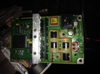
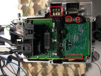
It turned out that the output voltages agree for the most part. I have highlighted some information in the picture below:
1. here on 3 pins the voltage of 5.5V when the key is switched on (+12V on the eighth pin) - on both boards it agrees
2. next 3 pins, turning the power steering shaft changes the voltage 0-6V - in accordance on both boards
3. on the same output the last two pins stiff 12V - same on both
4. the last output goes towards the shaft, I have some slight differences here, but practically looks OK in both cases.
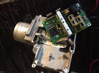
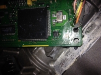
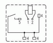
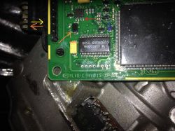
I ended up with a power steering unit, damaged with the symptom of a relay not working. I decided to solder it out, check it on the power supply and it turned out Ok. After applying 12v to pin 8 of the connector there was no voltage on the relay coil, I decided to find out where it was being generated from and by measuring, the paths led me to the MLX15119BB chip and the N-type dual mosfet transistor IRF7103.
.
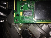
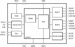
In the photo above, I have marked with a red arrow pins 7 and 8 are one of the inputs to the relay on which a negative is generated by switching on the mosfet, because on its pins 1 and 3 we have ground, pins 2 and 4 are gates which are controlled by the MLX chip. In blue I marked the second input to the relay and there should be a voltage there, probably 12v, but in my case there is none. As there is no technical documentation of the MLX chip it is impossible to identify the output. Maybe someone sitting on this topic has a datasheet of this circuit, the most I have managed to find is a block diagram see photo.
.
and quote: "MLX15119BB is a 5 channel meter controller. The MLX15119BB controls two independent sets of CMOS power bridges. The 10-bit angle is displayed using a 9-bit resolution per quadrant PWM, the frequency of which is set by a quartz oscillator. Power-on self-test detects open or shorted outputs for each logometer, and real-time angle tracking prevents display errors. The MLX15119BB can also control three small angle (90°) logometers. A three-wire serial link allows bidirectional communication with the microcontroller."
The failure of the relay to switch on is probably due to a circuit fault or blockage because, as we can see, there is an ERROR signal and a TEST signal which probably did not pass correctly. The lack of availability of the circuit at our place and detailed documentation does not allow me to check further. Maybe someone can give me their opinion on this issue, whether it is necessary to replace the chip or it is enough to clear the errors using the CAM bus which is located on the external 8 pin connector where we feed 12v to initialise the module.
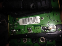
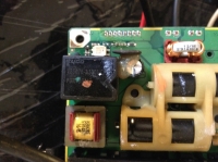
Another issue with the orange colour is the diode that was shorted in my case (the mosfet also had one N-type channel damaged on the diode side) and the outgoing signal also orange was not feeding 12v to the electronics in the motor. When I had the module soldered off the signal the yellow arrow on the pcb side was 0v, and when the module is soldered on there is 12v returning from the motor block. It is possible that this generated the error and disabled the MLX circuit. The next pin of this connector is ground. And as user " fan215" writes the last three pins are the shaft position and at the moment of movement we have voltages there from 0 to 6v, while the next pin had a constant 5v.
On the 3 pins from the left as the above user mentions I also have a voltage of 5.5v and this is the motor winding. The wide connector on the opposite side with lots of wires I have not checked.
And finally I will add that the reason for the immobilisation of the power steering was caused by doing a welding in the tractor of the bracket for its attachment, of course without powering the module, but nevertheless the problem arose, manifesting itself in a burnt diode, mosfet, blocking of the MLX or its damage. And one more thing after despite the relay not working, the main processor itself works because an 8Mhz waveform is generated on the quartz.
