logo elektroda
logo elektroda
X
logo elektroda

Car Alternator as High-Power 12-36V BLDC Motor - Affordable Driver Selection & Assembly

Mnster 26862 63
ADVERTISEMENT
Treść została przetłumaczona polish » english Zobacz oryginalną wersję tematu
  • #31 18359775
    Witch44
    Level 10  
    Hello everyone, after the first tests :)
    IVECO 28V 90A alternator.
    After dismantling the rectifier bridge, a nice surprise, the stator windings are wound with double wire. I connected them in series, thus increasing the operating voltage from 28 to 56V.
    Compared to the first alternator (even though I considered it a strong motor), the difference is huge. It is much stronger, faster, less power-hungry and more pleasant to the ear.
    Idle current on full gas and the controller set to 100% filling:
    -star- 0.6A
    -triangle-1.3A
    After 20 minutes of such fun, including braking the pulley, the alternator is very cold - even icy (you have to make a lot of effort to brake it a little and force it to draw electricity, I barely managed to get 16A ...).
    Some people are probably wondering why I am continuing this topic. Well, I have been observing the topics of unconventional drives for a very long time. The topics of alternators are often discussed. Unfortunately, the vast majority of such posts are theory and stormy discussions that cut off the topic at some point. I am a curious person, so I gathered all the internet knowledge that I found into a single whole and decided to test it in practice.
    My observations:
    - the alternator should under no circumstances be excessively rolled. The result of excessive oversaturation is a sudden, very large increase in current consumption, a drop in efficiency and a very rapid increase in temperature (This is probably the oversaturation effect of the poor quality iron used to build the stator). The effect disappears when the voltage is reduced to the rated voltage.
    -model controllers are not very suitable for continuous operation, let alone starting under load. Additionally, when the speed is too low in relation to the load, they simply cut off the power.
    -powering the rotor directly from the battery: the most optimal in both cases for me is half the rated voltage of the alternator.
    - powering the rotor with a voltage-reducing converter: in my case it didn't work out very well. Burnt 4 despite filtering noise from the rotor. Separation by both diodes and filters works well.
    That's it for the time being. Hope I didn't get bored. If anyone has any questions, doubts, or test suggestions, I will be happy to listen to you and check how it looks in practice. If you need any notes or photos from my experiments, I will be happy to share.
  • ADVERTISEMENT
  • #32 18362121
    rdt
    Level 25  
    Witch44 wrote:
    - the alternator should under no circumstances be overturned.

    Do you think the alternator from a passenger car should be powered from 12 V? of course from the inverter
  • #33 18362155
    jarek_lnx
    Level 43  
    Regarding overturning, the inverter gives a voltage proportional to the frequency, so the question is at what rotational speed should be 12V?
    This also applies to core saturation, the higher the frequency, the higher the voltage can be given without leading to saturation.
  • #34 18362169
    rdt
    Level 25  
    I didn't think the fact - it was about the voltage to power the inverter - I gave it 24v and in my opinion, nothing was wrong with the alternator, but: - the condition was to select the rotor current.
    When it is too SMALL, it overheated very quickly.
  • ADVERTISEMENT
  • #35 18363262
    Witch44
    Level 10  
    Referring to my statement about the shift - it would be appropriate for me to elaborate on my statement a bit more. I mean the windings wound around the stator.
    My power source is 48V 32A (above will eject the protection).
    The driver is 48V maximum and is limited to those 32A.
    Effect:
    -Alternator VALEO 14.4V 150A - with factory delta stator windings it started to choke at 70% of filling (sudden increase in temperature without load, disproportionate increase in current consumption and lower and lower speed increase. It will be disassembled soon, I will try to depict it in the video).
    - IVECO 28V 90A alternator - test on the factory winding connection - the same effect but with about 90% filling. The windings were double wound so I separated them and connected them in series which theoretically should allow me a higher supply voltage.
    The alternator works completely differently, much smoother, it is stronger, absolutely no temperature increase and the rpm is much higher.
    The video below shows the work after the alternator has been rebuilt. The analog ammeter practically did not budge at the start. At maximum filling, it showed only 1A.

    https://filmy.elektroda.pl/21_1577470854.mp4

    As for voltage- rotor current. For me, the ideal solution was half the rated voltage of the alternator. With Valeo below 7V, the alternator can break at load, so to speak, and you have to let the gas go and start again, above 9V it starts consuming electricity. I power the alternator from IVECO from 13V and it's perfect.
  • ADVERTISEMENT
  • #36 18363722
    jarek_lnx
    Level 43  
    Higher excitation currents are good when we want to achieve low speeds and high torques, and vice versa, if the controller was adapted to excitation control, this could be used. I used Permanent Magnet BLDC excitation attenuation to pull higher RPM. Old trains had excitation weakening positions on the controller :)
  • #37 18364147
    Witch44
    Level 10  
    You're right with these excitation currents. I'm just looking for a compromise between power and speed. In my case it is a low-efficiency transmission consisting of a worm gear and here I cannot afford too low excitation current, even when the vehicle accelerates.

    Added after 2 [minutes]:

    However, I can not understand this sudden breakdown of the Alternator characteristics with too high current. With bldc engines, I did not notice such a phenomenon.
  • #38 18413226
    rdt
    Level 25  
    I'm wondering if I should not stick at home and maybe it will be better?
    https://www.youtube.com/watch?v=5BXH6GP8mPU
    Halls are 2.9 on the Allegro.
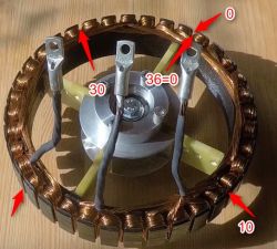
    in my alternator valeo 93 r the number can not be read, but there are also 36 nurseries as in the film frame.
     Car Alternator as High-Power 12-36V BLDC Motor - Affordable Driver Selection & Assembly
  • #39 18413394
    Witch44
    Level 10  
    I wonder how this overlaps with the triangular shape of the rotor teeth and the large gap between them. I am curious about the effect.
  • ADVERTISEMENT
  • #40 18556205
    rdt
    Level 25  
    the effect is that it does not fit in the nursery - at least in my case.
    There is someone on the Endles forum who did it and put it in the nursery catch - the distance between the rotor and the stator is not large here, there would be no problems.
  • #41 18877950
    LemuRR 11
    Level 26  
    @ Witch44
    Have you thought about using permanent magnets in the rotor?
    Does this configuration of connections weaken the engine very much?

    The subject comes back to me like a wave. I let go of the alternator from the poldek, it cannot be forced to work effectively as an engine.
  • #42 18878781
    Witch44
    Level 10  
    @lemurr 11
    1- permanent magnets permanently block the possibility of rotating at low load of the alternator (driving under high load requires a high magnetic field of the rotor. Unfortunately, high magnetic field affects the rotation, the engine is very strong, but its speed is low ... if it is too low - the engine falls out of sync and begins to squeak, losing thrust. In the other direction, if I am driving on level ground, without much resistance, I reduce the rotor current, which makes it faster and I can go faster)
    2- such configuration of the stator connections was caused by the alternator heating when powered from 48V on full gas.
    By trial and error (there were a lot of them) I came to a scheme (tested on 2 alternators):
    12V alternator - max 24V power supply
    24V alternator - max 48V power supply
    Both double windings connected in series. When connected in parallel, they warmed up under load and took a high current (throttle trigger fully pressed).
    It had no effect on the power of the alternator, but it greatly extended the driving time. the vehicle from my post is able to haul a load of 1300 kg in the field (I checked the weight of the trailer with the load) for almost 3 hours. After such fun, both alternators were slightly warm.

    Added after 9 [minutes]:

    @lemurr 11 in your place, I would not let go of this alternator, I would only increase its gear ratio. 1/42 came out for me and it's perfect for hard work. The speed is not stunning, about 12 km / h. I'm just looking for some tiny gearbox for this.
  • #44 18924345
    LemuRR 11
    Level 26  
    How is it with a star-delta connection?
    In the case of a star, one of the three windings is not used in a given phase.
    Better if the windings are wound with double wire, connect them in series? Do I leave in parallel and star connect?
  • #45 18925777
    rdt
    Level 25  
    Witch44 wrote:
    Both double windings connected in series. When connected in parallel, they warmed up under load and took a high current (throttle trigger fully pressed).
    It had no effect on the power of the alternator, but it greatly extended the driving time. the vehicle from my post is able to haul a load of 1300 kg in the field (I checked the weight of the trailer with the load) for almost 3 hours. After such fun, both alternators were slightly warm.

    I understand that yes, connect in series only in the right way - so that the current does not flow in one direction along the coil and then with the other wire "returns" because it will rather heat up "a little"
  • #46 18928024
    _patelnia_
    Level 5  
    I will step on it, I have an alternator from Mazda 626, probably 75A. I started by checking how the winding is connected, it was in the star, and with the individual windings in parallel. I disconnected everything in the order (A, B, C windings) and connected in series and in a delta. I still have to buy a driver, I was thinking about the gt1500 with control without hall sensors. Will it not be too strong?
    And what voltage to apply for the excitation at the beginning, I saw above that someone wrote around 7V.
  • #47 18929608
    LemuRR 11
    Level 26  
    I wrote that it was 7V, but this is the case of an alternator from FSO.
    Everyone else will have a different rotor resistance which will significantly change the current through the rotor flowing.
    You have to choose the rotor current by trial and error.
  • #48 18934946
    rdt
    Level 25  
    Buddy Lemur - one question, how did you give this 7 V through some regulator from the same source or from a completely different one ??
  • #49 18936554
    LemuRR 11
    Level 26  
    Sequentially A converter on Lm2596, capacitor choke, diode capacitor, rotor
    Choke about 100mH, 100uF capacitors
  • #50 18936649
    _patelnia_
    Level 5  
    LemuRR 11 wrote:
    Sequentially A converter on Lm2596, capacitor choke, diode capacitor, rotor

    Will the high voltages generated on the rotor after disconnecting the converter not damage with such a set?
  • #51 18939300
    LemuRR 11
    Level 26  
    Another alternator, more problems.
    Unfortunately, it is powered from 48V, no-load current over 10A. 0.3A impeller
    I did not notice a sudden increase in current, it increases linearly with the revolutions. Reducing the supply voltage causes a drop in speed.
  • #52 18941781
    LemuRR 11
    Level 26  
    Connecting the windings in series reduces the no-load current to 4A, but it is still linear. The electricity grows in line with the turnover.

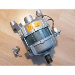
    I am thinking more and more about the use of the washing machine motor, the so-called "direct drive"
    After proper rewinding, it should have a fairly specific power
  • #53 18944815
    manfredi
    Level 9  
    Hello, I have a 14v 140a alternator, after unfolding, it turned out that there are 4 wires for each phase, so I conclude that it is wound with a double wire, which will allow me to power it with 28v voltage by connecting the coils in series, now the question is what regulator to buy to maximize the potential of the future engine, is it enough to model 24v 100a Can I use the regulator typically for bicycle motors with a minimum voltage of 36v?
  • #54 18946374
    LemuRR 11
    Level 26  
    Let go of the modeling ESC, it will spin, but you will not get high power, because you will burn the driver immediately.
  • #55 18947543
    manfredi
    Level 9  
    good what you recommend, ready for 24v 1500w voltage :D
  • #56 18949117
    LemuRR 11
    Level 26  
    At Chinese you will find at affordable prices.
    There is a lot of work with the bldc controller, after a year of work, I abandoned the topic in favor of a ready-made one, which is incomparably better. At 24V and 1.5kW, the current is over 60A. Add more losses. For this power it is a minimum of 36V, unless you lose half of the power as heat.

    The very idea of using an alternator as an engine is cool, but for me it is too low efficiency, and decent 24V alternators cost a lot.

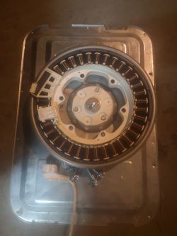
    As I considered in the post above, I finally tried to get a washing machine motor. Puki looks promising, after rewinding I will let you know about the effects.
     Car Alternator as High-Power 12-36V BLDC Motor - Affordable Driver Selection & Assembly
  • #57 18950795
    LemuRR 11
    Level 26  
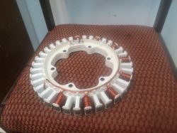
    The next day - rewinding
    7x1mm after 11th thread
    Paws hurt already, but I hope the results will be good :)
     Car Alternator as High-Power 12-36V BLDC Motor - Affordable Driver Selection & Assembly
  • #58 18950981
    Anonymous
    Level 1  
  • #59 18950993
    kkknc
    Level 43  
    The first was LG. And now almost every company has it on offer.
  • #60 18951000
    LemuRR 11
    Level 26  
    This is a so-called "direct drive" or "smart drive" (depending on the manufacturer.
    They will drive the drum directly.
    Unfortunately, the factory winding turned out to be made of aluminum, so I skipped the configuration of the factory winding.

Topic summary

The discussion revolves around the feasibility of using a car alternator as a high-power BLDC motor powered by 12-36V, focusing on affordable driver selection and assembly. Users share experiences and challenges related to modifying alternators for motor use, including the removal of rectifiers and connecting to various controllers. Key points include the importance of excitation current management, the effectiveness of different wiring configurations (star vs. delta), and the use of specific controllers like the Chinese 48V 350W e-bike driver. Users also discuss the performance of different alternators, such as those from Valeo and IVECO, and the potential of washing machine motors as alternatives. The conversation highlights the need for careful tuning of rotor currents and the impact of gear ratios on performance.
Summary generated by the language model.
ADVERTISEMENT